3. Computer-Controlled Cutting
View Checklists
Checklist: Group assignment
- Do your lab’s safety training
- Characterize your lasercutter’s focus, power, speed, rate, kerf, joint clearance and types.
Checklist: Individual assignments
- cut something on the vinylcutter
- design, lasercut, and document a parametric construction kit, accounting for the lasercutter kerf
View Ideas
- Lasercutter
- LUEDO dock charger for the wall
- (plastic) iPad portrait holder/prop
- (plywood) slim under desk tray for keyboard, mouse and iPad
- (cardboard) organizers for A4 sheets, postbox
- use Cuttle.xyz
- Vinyl cutter
- Luedo Glyph sticker
- PCB stickers
- charging pad stickers
- magnet ring sticker
- cut stickers for the magnets to attach everything after assembly
- cut stickers to mount a board in the housing
- MainBoard sticker
- SensorBoard sticker
- LightBoard sticker
Laser cutting
RDWorks - Thunderlaser (Software)
The Laser cutter in our Lab is operated with the RDWorks software
RDWorks - ThunderLaser
Laser Cutter Characteristics 
Projects
Decorative Night Lamp
I wanted to build a small desk lamp, which is made of laser cut wood or MDF. Therefore, I scrolled on 3axis.co for inspiration or maybe to find a design which could be modified. After a while and many open tabs, I found a design which I liked. It's called Laser Cut Decorative Night Lamp on 3axis.co. The Lamp is made of a cuboid and some paper or fabric behind the cutouts.
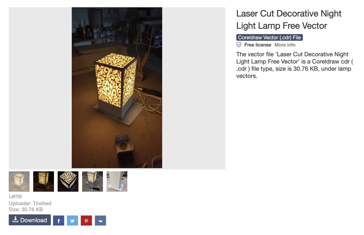
I opened the decorative_night_lamp.cdr file in Inkscape and exported it via the menu 'File' > 'Save As...' as a .dxf file type R14. During export, I disabled flattening of Bézier curves and low poly mode.
In our laser software RDWorks - Thunderlaser I removed the slots in the middle of the lamp, since these are not needed when everything is assembled with glue. Since the design was created for a 3 mm material, I chose not to edit the file and search for a fitting material in our Lab. MDF in 3 mm was available, and I configured the cutting parameters as shown below.
min Power: 80%
max Power: 80%
Speed: 11mm/s
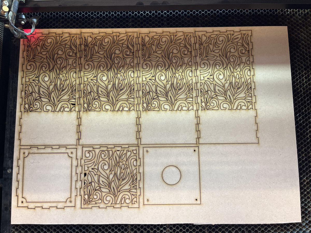 This is the result after 55 minutes.
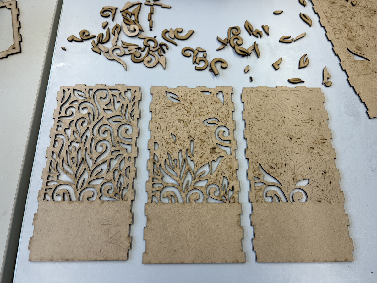 Depending on the position, the material has not always been in focus. Therefore, some parts were not fully cut due to an uneven laser bed.
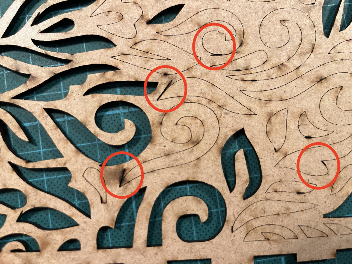 Unfortunately there is a weird defect in the file: Some curves are misinterpreted, and 'extra lines' are added. These areas are burned heavily since the laser beam ran over this area most likely multiple times.
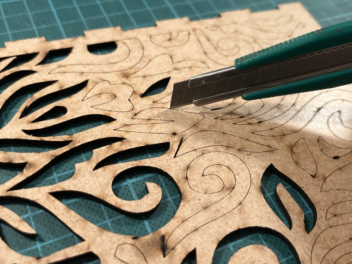 I removed the remaining pieces with a box cutter. I should have adjusted my settings in the first place, removing the pieces took 1.5 h of tedious manual work. Now all the laser cut parts were ready for the next steps.
To create the nice opaque effect of the light shining through the laser cut pattern, I used a fiber paper to prevent looking directly into the light source.
For the installation of the E27 lamp socket, I still needed an adapter plate to prevent the screws (wood, countersunk 2×12) from being exposed after installation. At the time I had no access to the laser cutter and needed to manufacture an adapter plate at home with a simple drum saw.
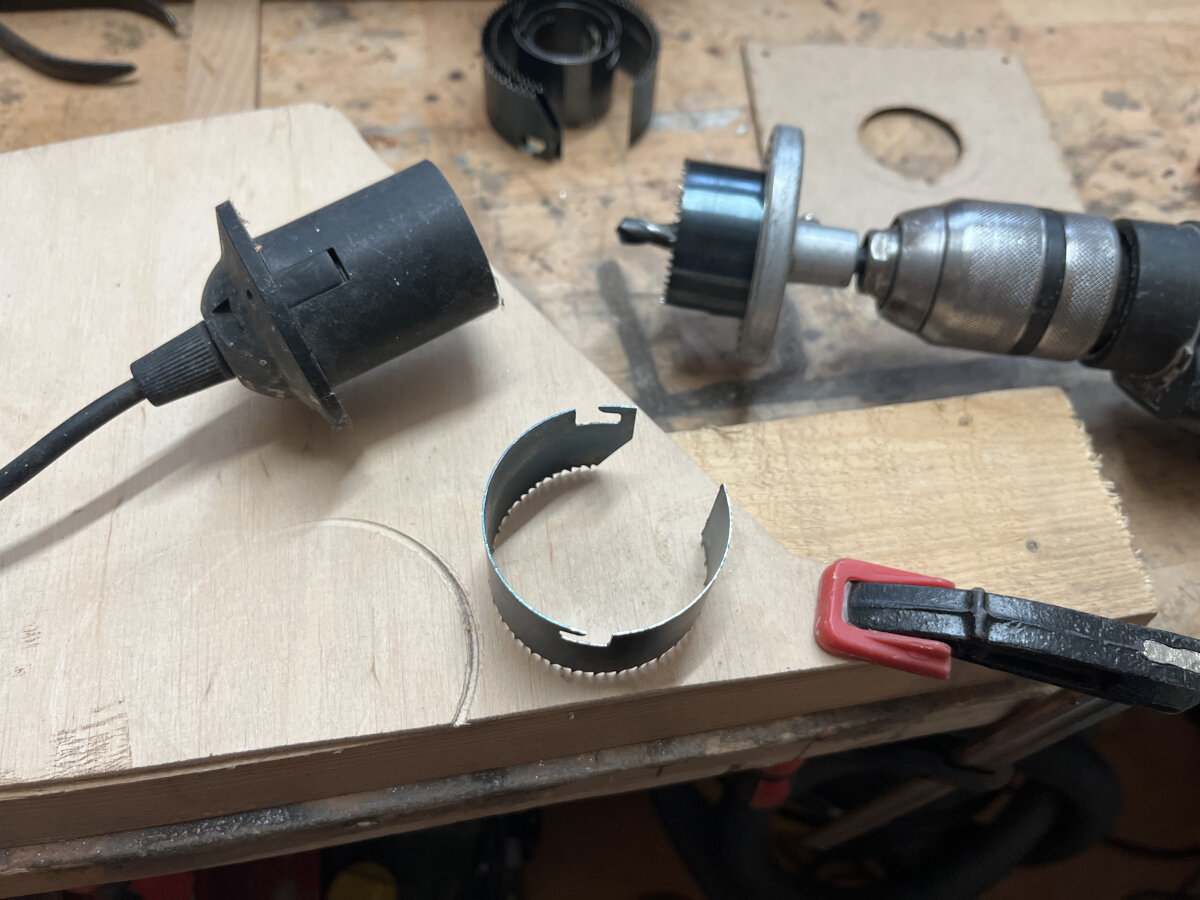
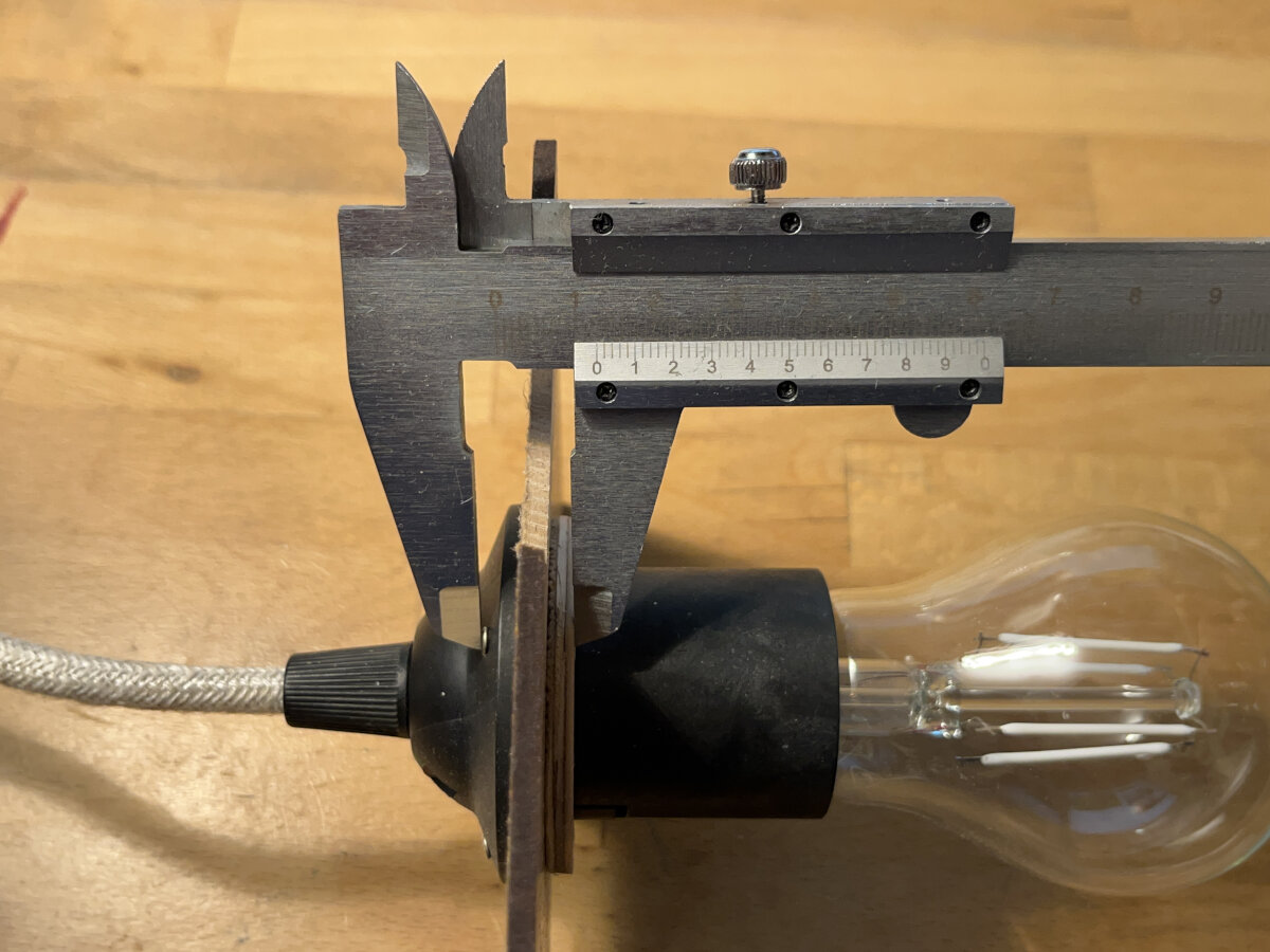
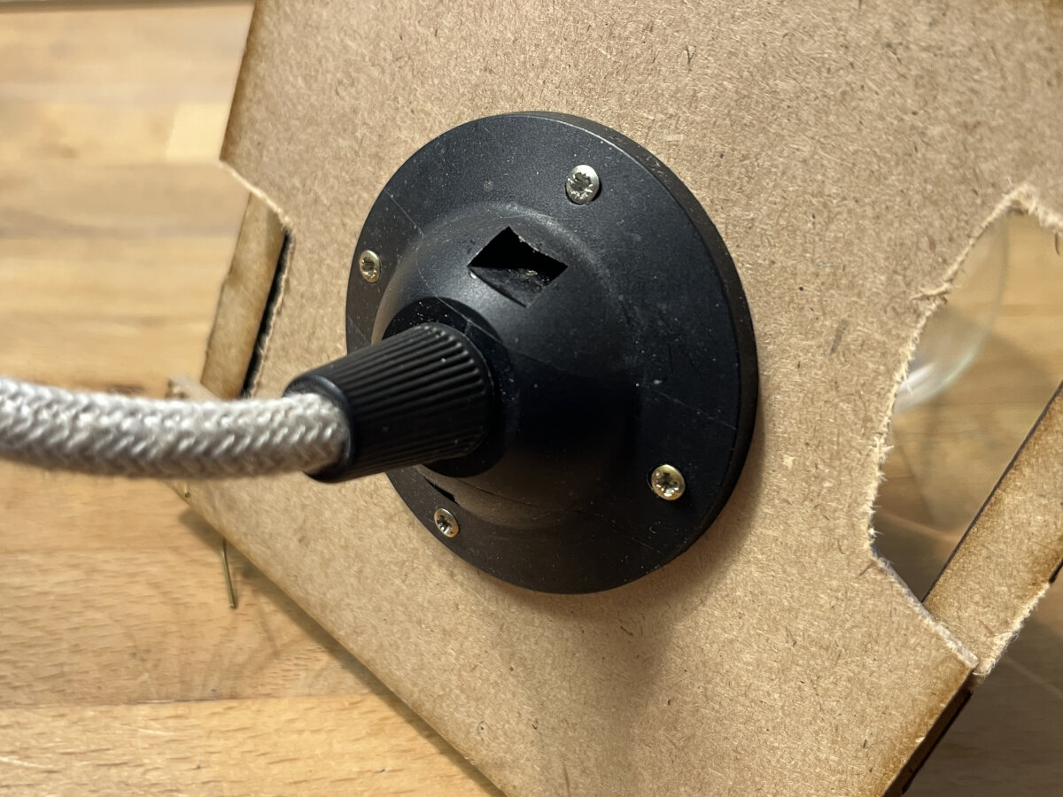
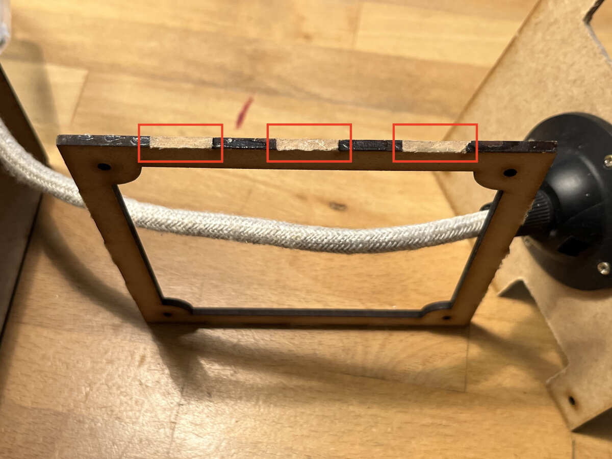
As mentioned above I removed some slots in the design to make it more streamlined, but I forgot to remove the tabs on the opposite side, so I removed them with a box cutter.
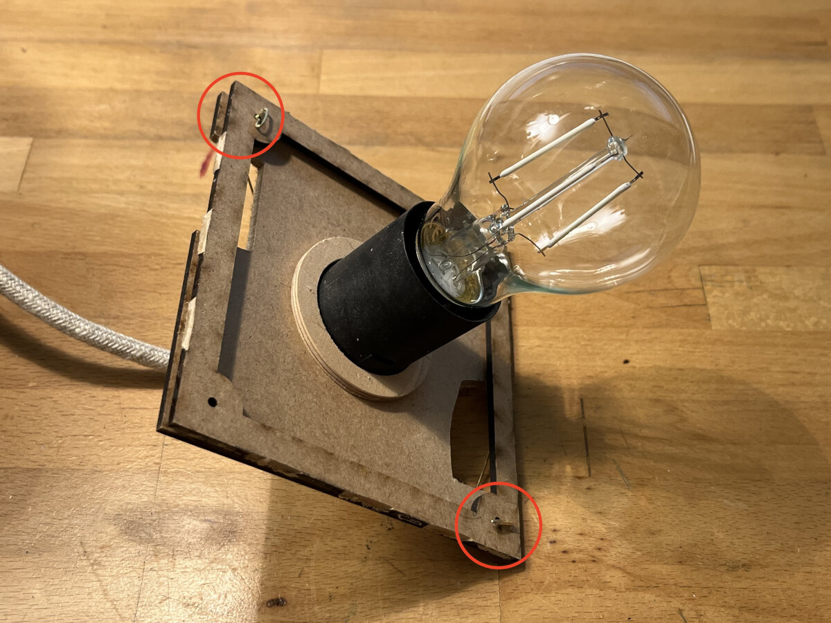
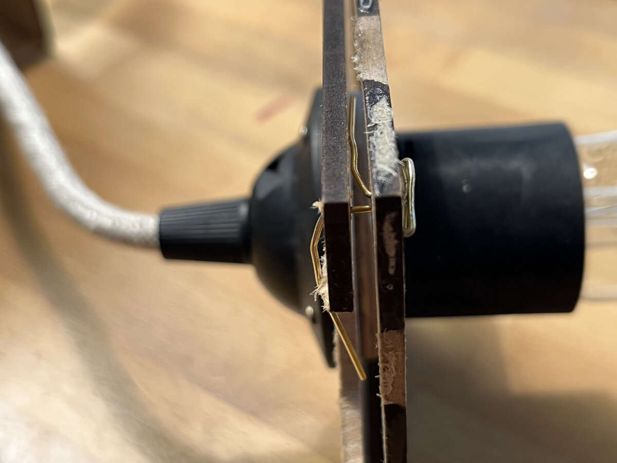
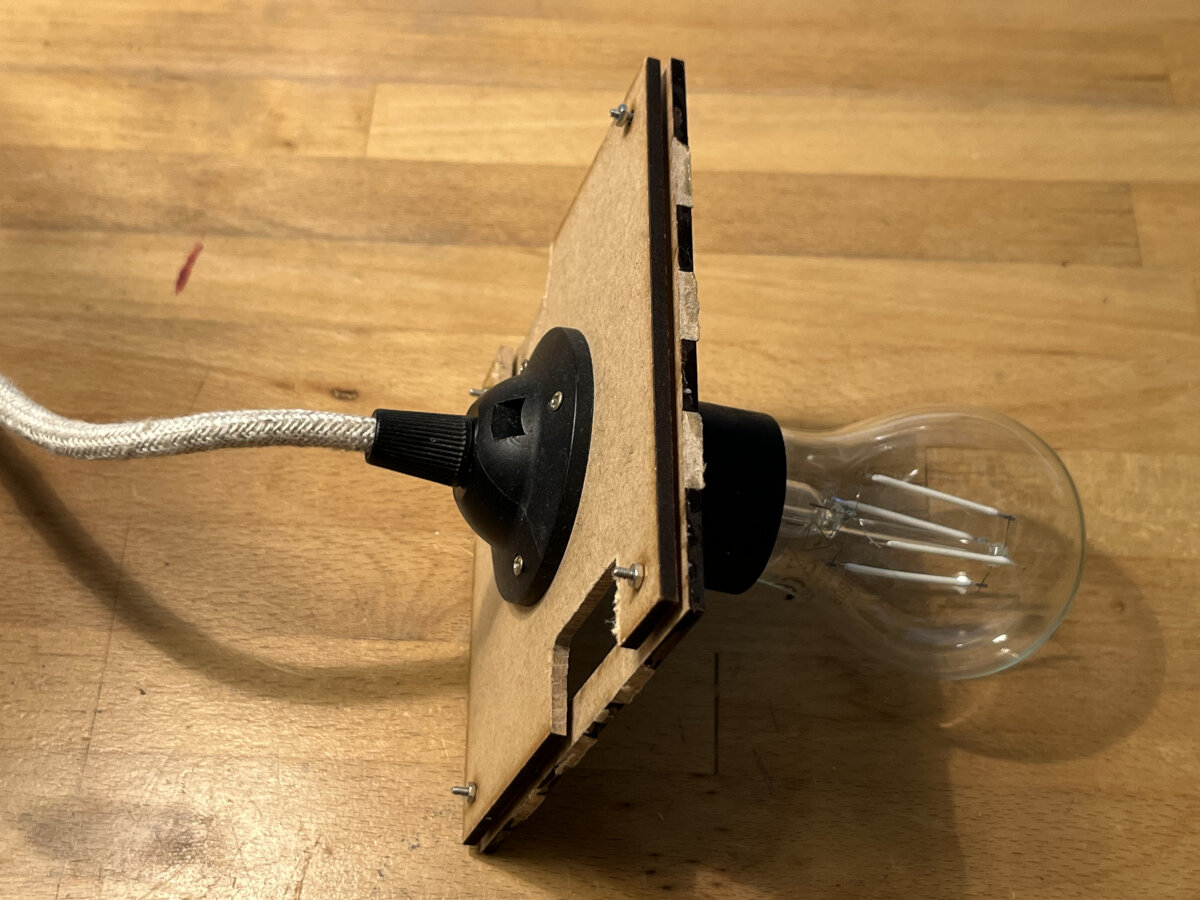
In the original design nothing was specified how the lamp platform should be connected, so I bent some paperclips into shape, which later got replaced with M2x12 screws.
For the paper backing I used white wood glue, because its viscosity is low enough to prevent soaking into the visible area of the cutouts.
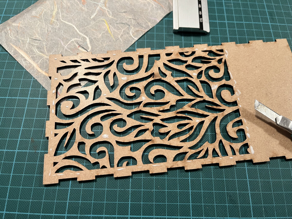
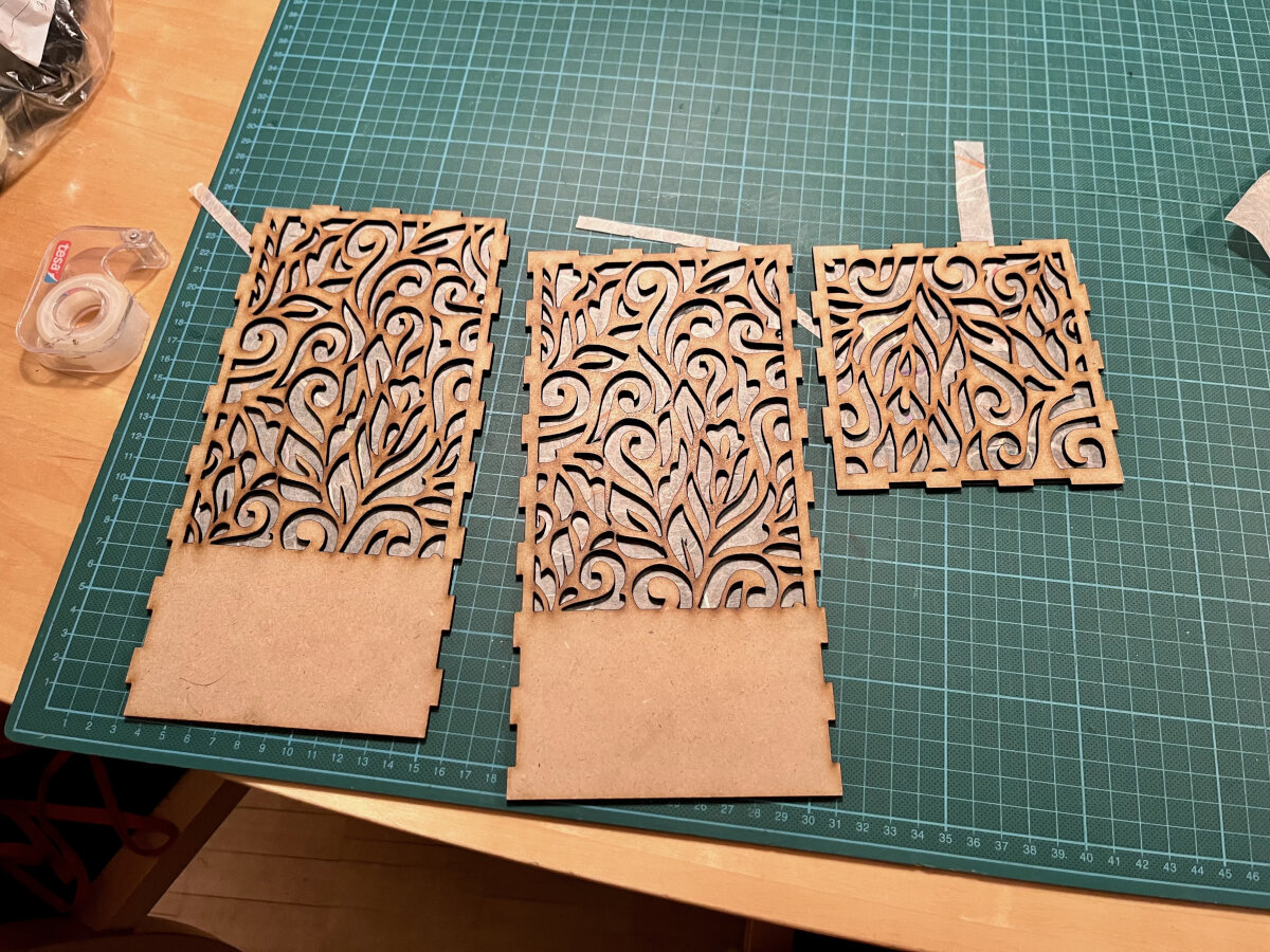
Now it was time to assemble the whole lamp and glue the tabs together. I used the box cutter to precisely apply the right amount of glue, while trying to avoid leakage to the outside.
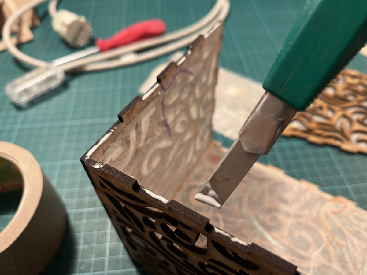
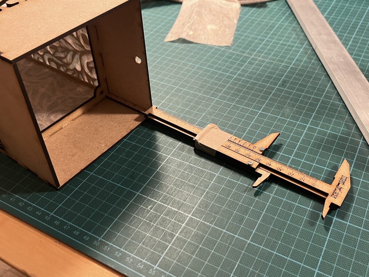
After all five sides were installed, I used our self-made calipers from our Lab to adjust the right position for the mounting frame.
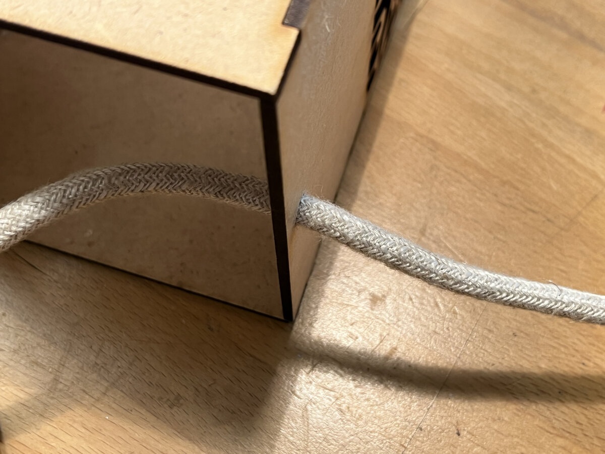
To turn the object into a lamp I drilled a hole for the cable and assembled the electrical wiring.
WARNING
This is not a tutorial on how to wire electrical equipment. Wiring electrical equipment for 230V AC is dangerous and should only be executed by a professional or checked afterwards by a professional before initial commissioning.
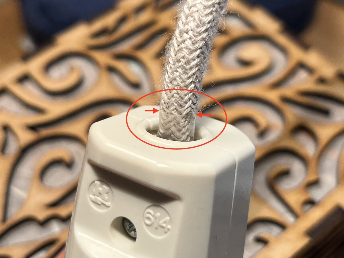
For the cable I used a textile cable with a braided linen sheath to match the self-made look of the lamp. The switch was not available in a cream color, so I chose the transparent version.
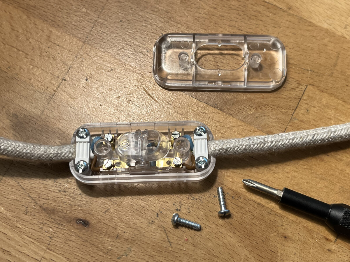
Note: When working with textile cables of any kind, it is necessary to first tape the sheath before cutting the cable. This prevents the cable's linen sheath from unraveling.
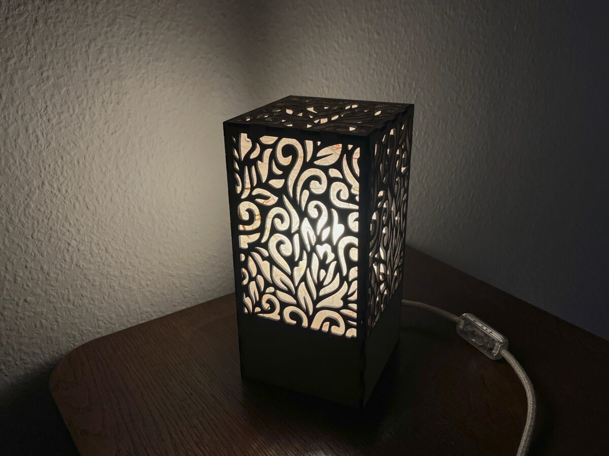
After many steps and a couple of manual 'adjustments' the Night Lamp is finished!
Lamps:
Apart from the manufactured design I saved some links for possible later projects.
(All designs from 3axis.co)
Bending wood:
- diamond
- lampshade
Asymmetrical:
- half open ellipsoid
Spherical/Dodecahedron/Icosahedron:
- Dodecahedron with pattern
- Dodecahedron with pattern_2
- Icosahedron with pattern
Box/Cube shaped:
- organic pattern
- multiple patterns
- geometrical pattern
- islamic pattern
- cube on corner
Cylindrical/Pentagon/Hexagon:
- without blinding?
- simple design
- cardboard
- Pentagon standing lamp
- stretch mesh
Special:
- self supporting
General:
- twisted lamp
- wave lamp
- wave lamp_2
- 3d surface lamp
- rotational swirl
- very fine pattern,
- cardboard lamp
- cardboard, waving pattern
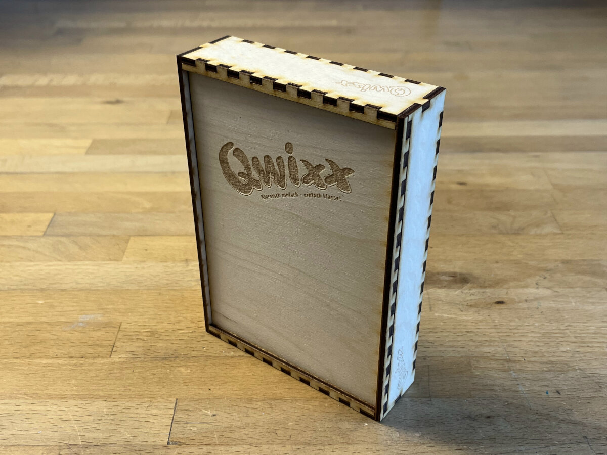
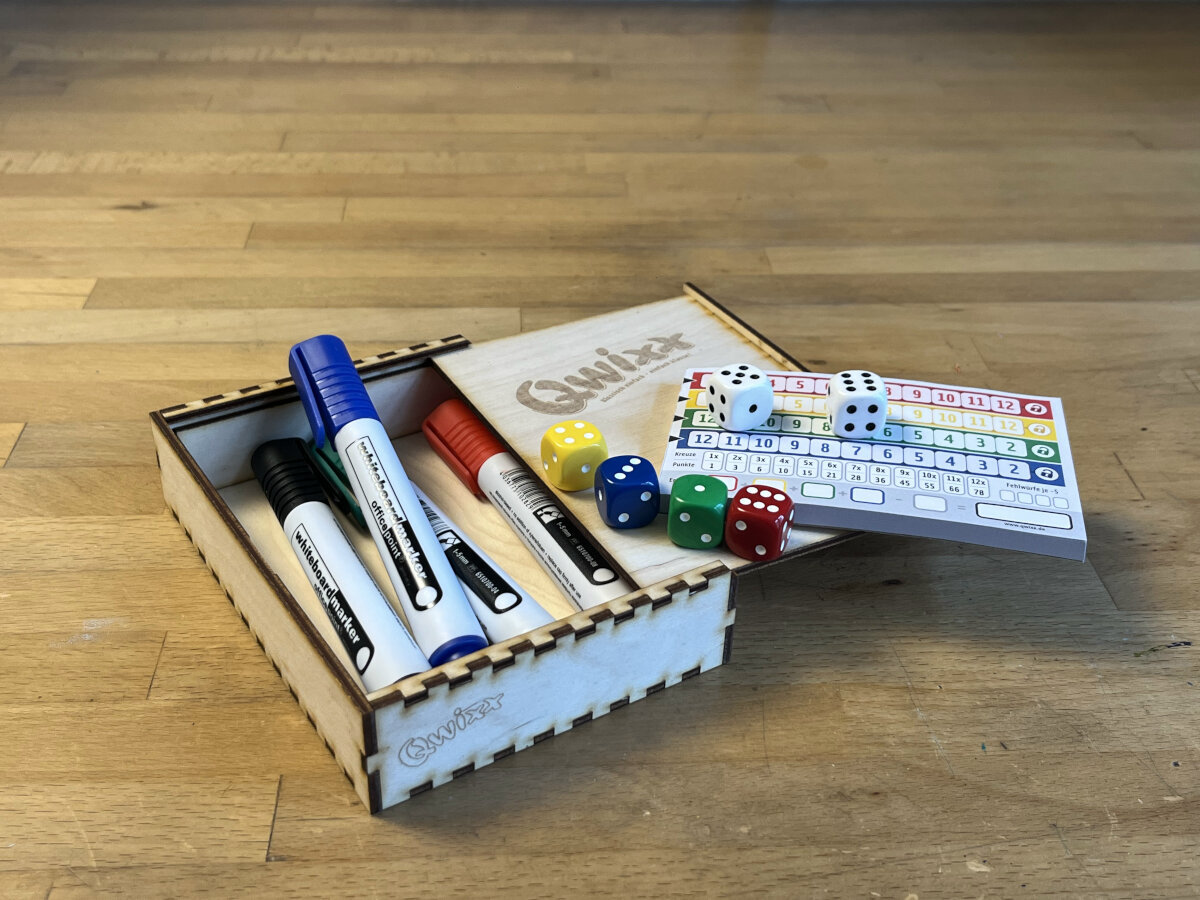
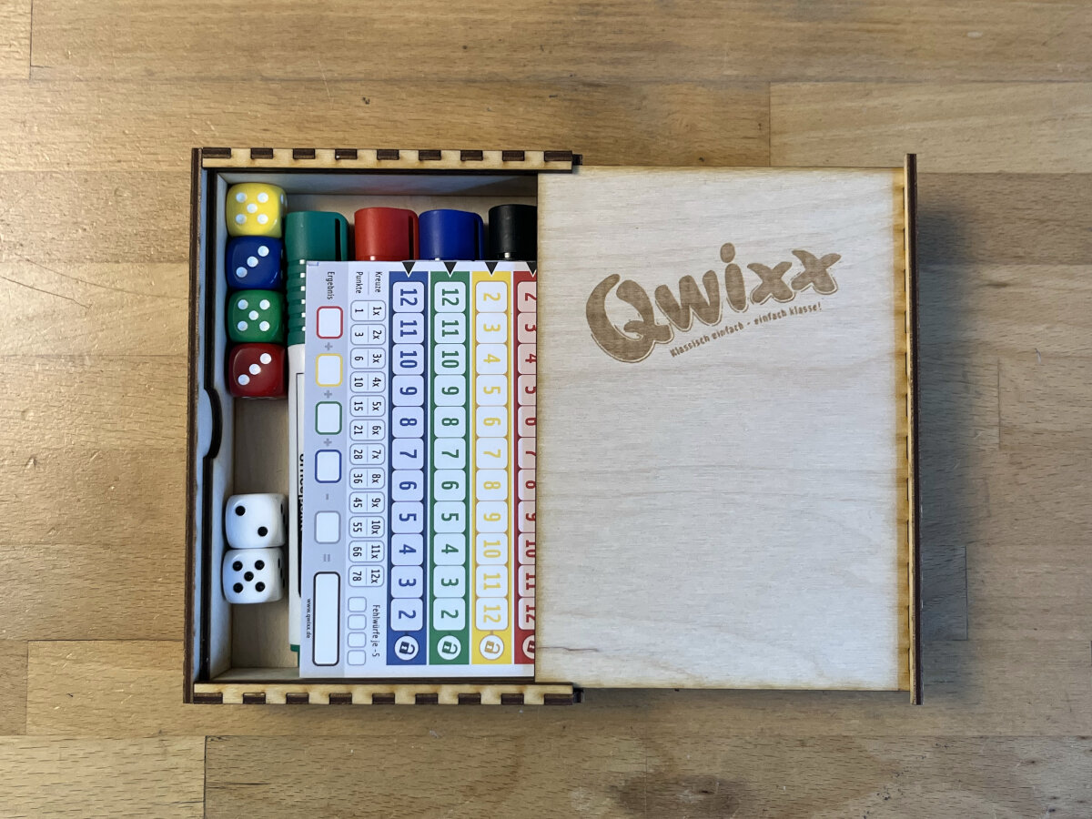
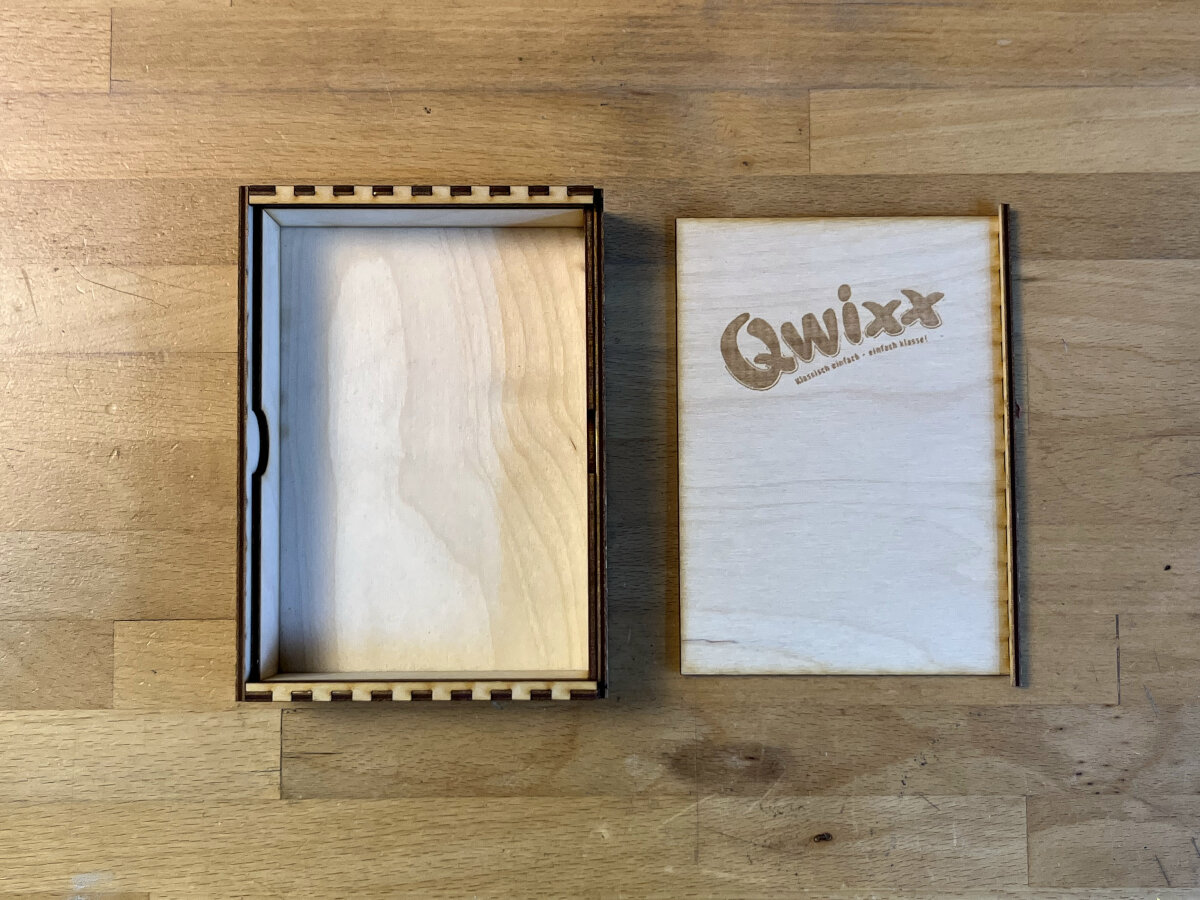
Cardbox - GameBox for Qwixx Dice game
During the assignment for Computer-Aided Design - Week 2 I designed a gamebox with Boxes.py and Inkscape. This design was ready to be fabricated during this week's assignment.
Manual Nesting
Since I wanted to optimize for leftover materials I decided to manually nest my design to an image of the remaining stock.
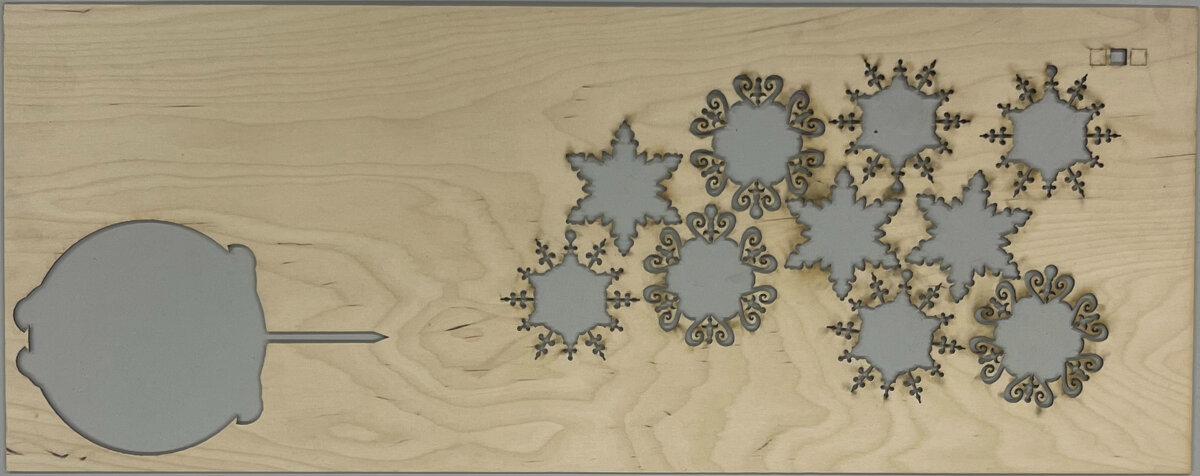
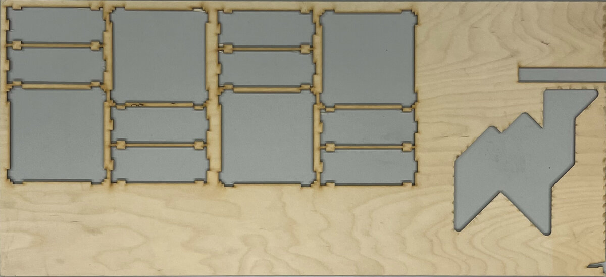
I laid the material flat down on the table and chose the zoom lens of my phone to reduce the optical distortion. I went far away from the material to be as parallel as possible to the surface. In the next step, I measured the physical size of the sheets and afterwards cropped the image accordingly.
Then it was time to nest all the parts on the sheets in Inkscape. I always left some margin for error, to allow for slight misalignment in the laser cutter.
After all pieces were nested in place, I chose the "Save As" (not export!) feature from Inkscape and saved the design as a .dxf file type R12.
Production
For the production process, I aligned the sheets as precisely as possible. Then I checked if everything is parallel to the gantry of the machine and started the actual cutting process. At that time I encountered a couple of errors...
Frame Slop
Frame slop occurs when the loaded design is too large for the working area. Therefore, it is needed to design the file slightly smaller than the active working area of the laser cutter.
Frame slop can occur even when the loaded design is smaller than the active working area. In this case the design often contains some kind of white spaces which are outside the allowed boundaries.
Fix: Use Inkscape "Resize page to selection" feature or manually set page size to your laser cutter's active area.
Exported .dxf always contains all layers
Fix: Not yet clear how to fix it in Inkscape. Optionally process the file in AutoCAD and export individual layers.
Network connection
Hot Fix: Use a USB flash drive to transfer the file manually to the laser cutter.
Fix: Debug the LAN network and assign the right IP address to the laser cutter.
Nicht genug erw. Sper Bitte 'Esc'
This error occurs when the working origin is on the boundaries of the working area of the machine. It usually occurs when engraving a pattern that is on the edge to the maximum working area of the laser cutter. The laser head swings from left to right in x-direction. For this motion it needs some length to accelerate and decelerate.
Fix: Set the working point origin not on maximum boundaries of the active area or redesign the file with a 15 mm white space around engraving patterns. Avoid placing engraving patterns directly on the edge of the active area.
Note: Just deactivating geometry that is close to the boundaries of the active area is not enough because the software will interpret as well hidden geometry, and still display the arrow.
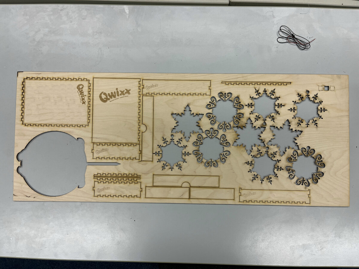
Success! I was quite satisfied with the result. All my measurements, that I did in the first place turned out to be worth it and no part got damaged by missing material.
Assembly
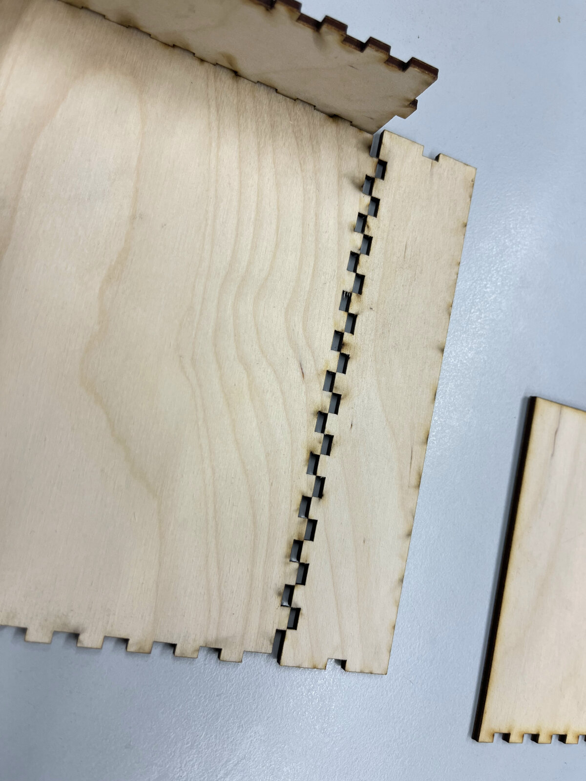
During the assembly process I noticed, that the fitment was a bit too tight. After trying my best with my hands I switched to a hammer for assembly. I used an old piece of wood to protect the surface from dents caused by the hammer.
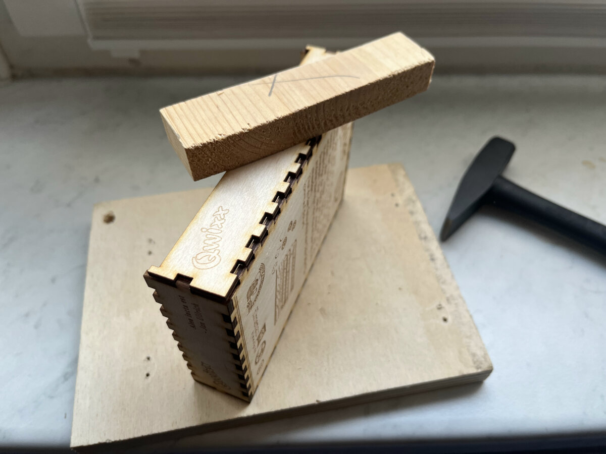
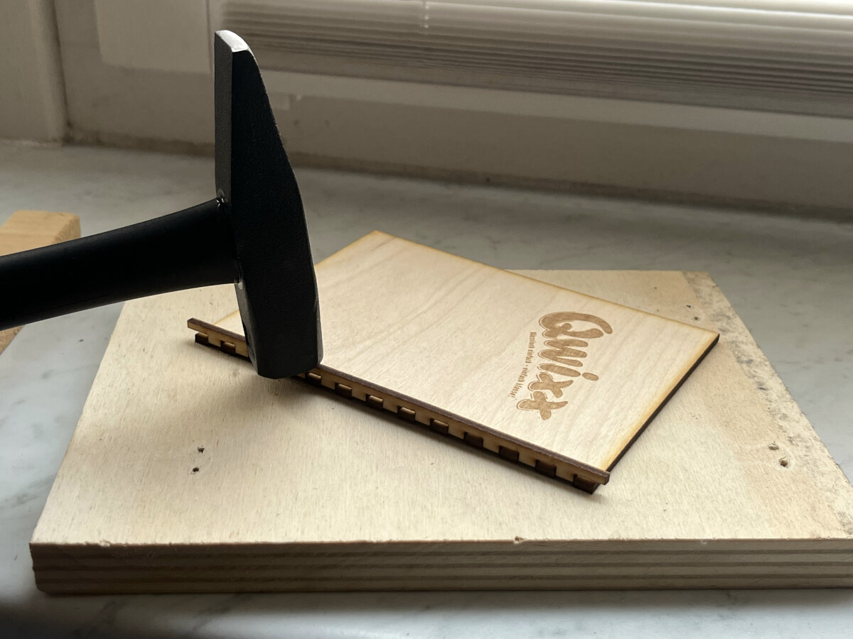
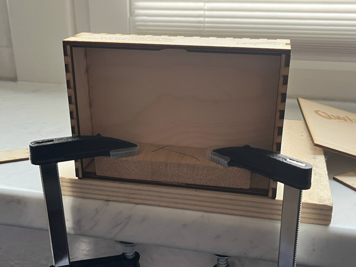
Result
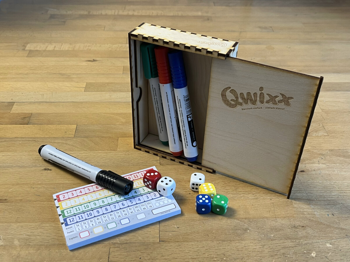
Vinyl cutting
For the vinyl cutting assignment I decided to cut a text sticker for our meeting room door. We designed the sticker within Inkscape and then exported the file as a .dxf type R12.
In our Lab, we are using the Summa Vinyl cutter. This is a very large machine that could be used for advertisement cutting, but in this case, it will just be used for a small sample object.
To control everything the Summa GoSign software is used.
Machine Setup
-
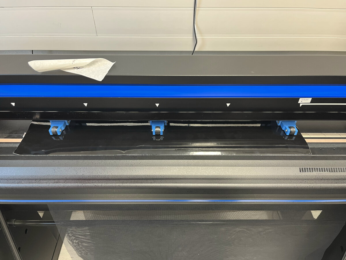
Set the lever in the right position to raise the transportation rolls, clearing the way to insert the material.
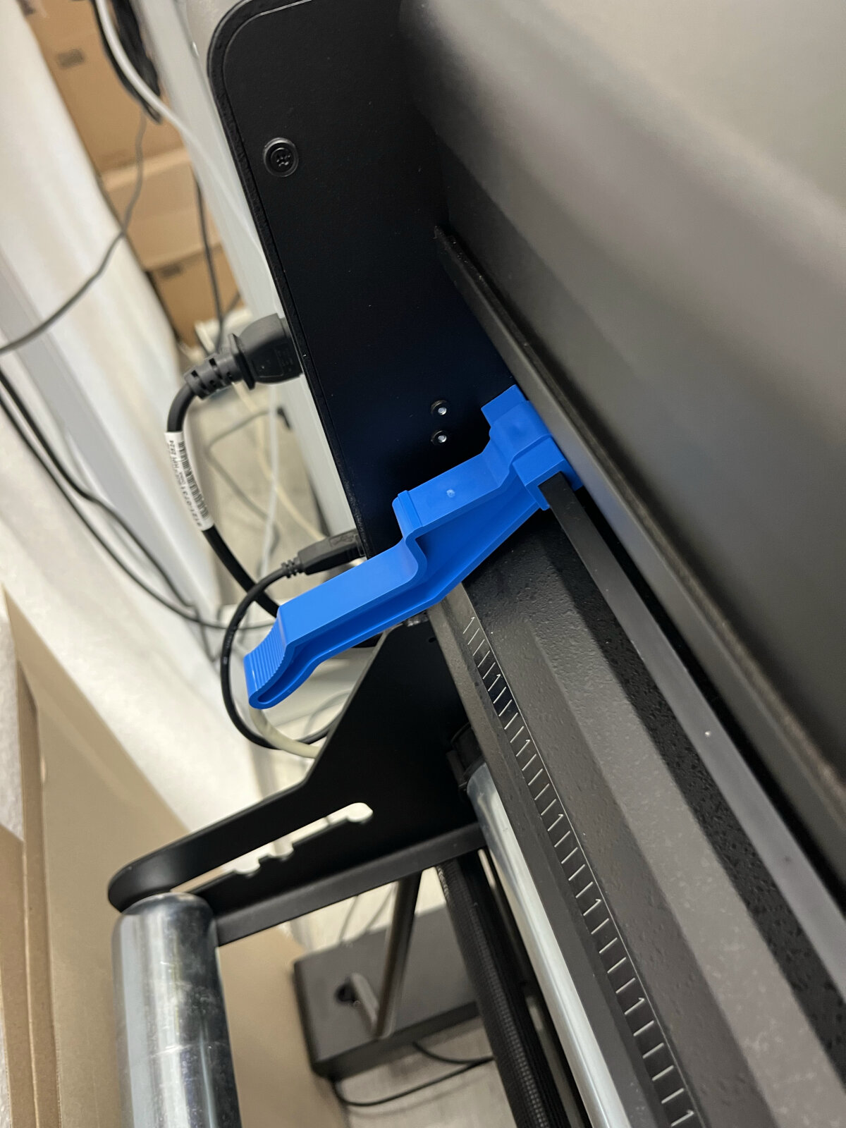
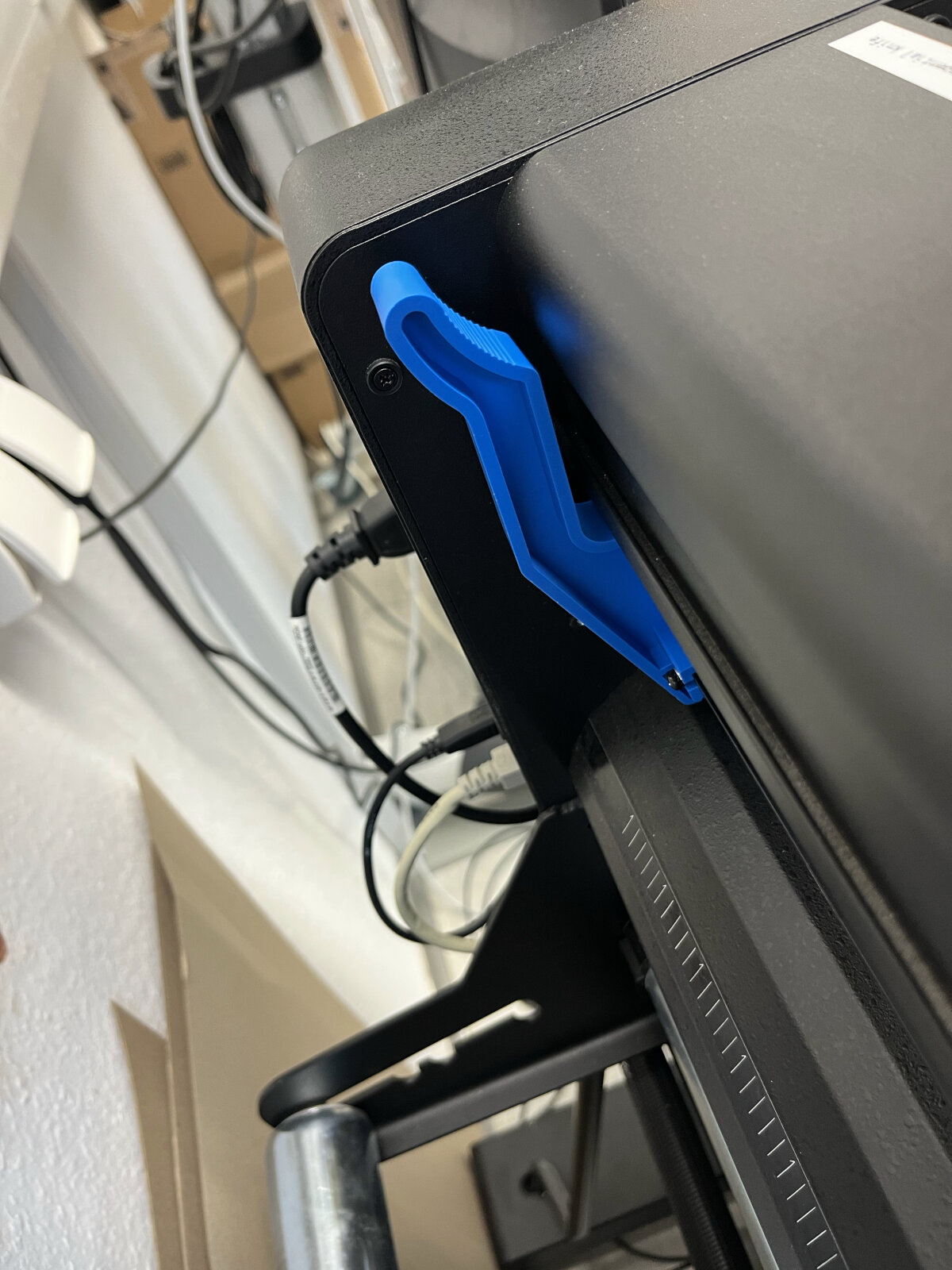
-
Install the roll on the holder and make sure the vinyl is nice and smooth without any wrinkles
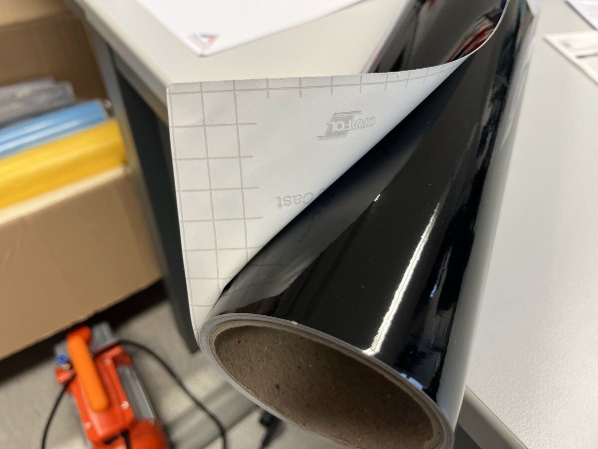
-
Insert the vinyl and make sure the material detection sensor is covered.
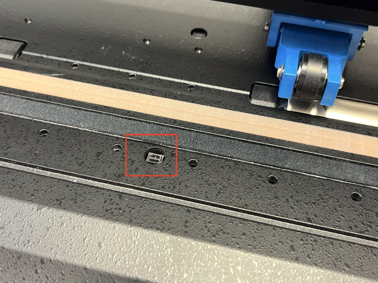
Software
-
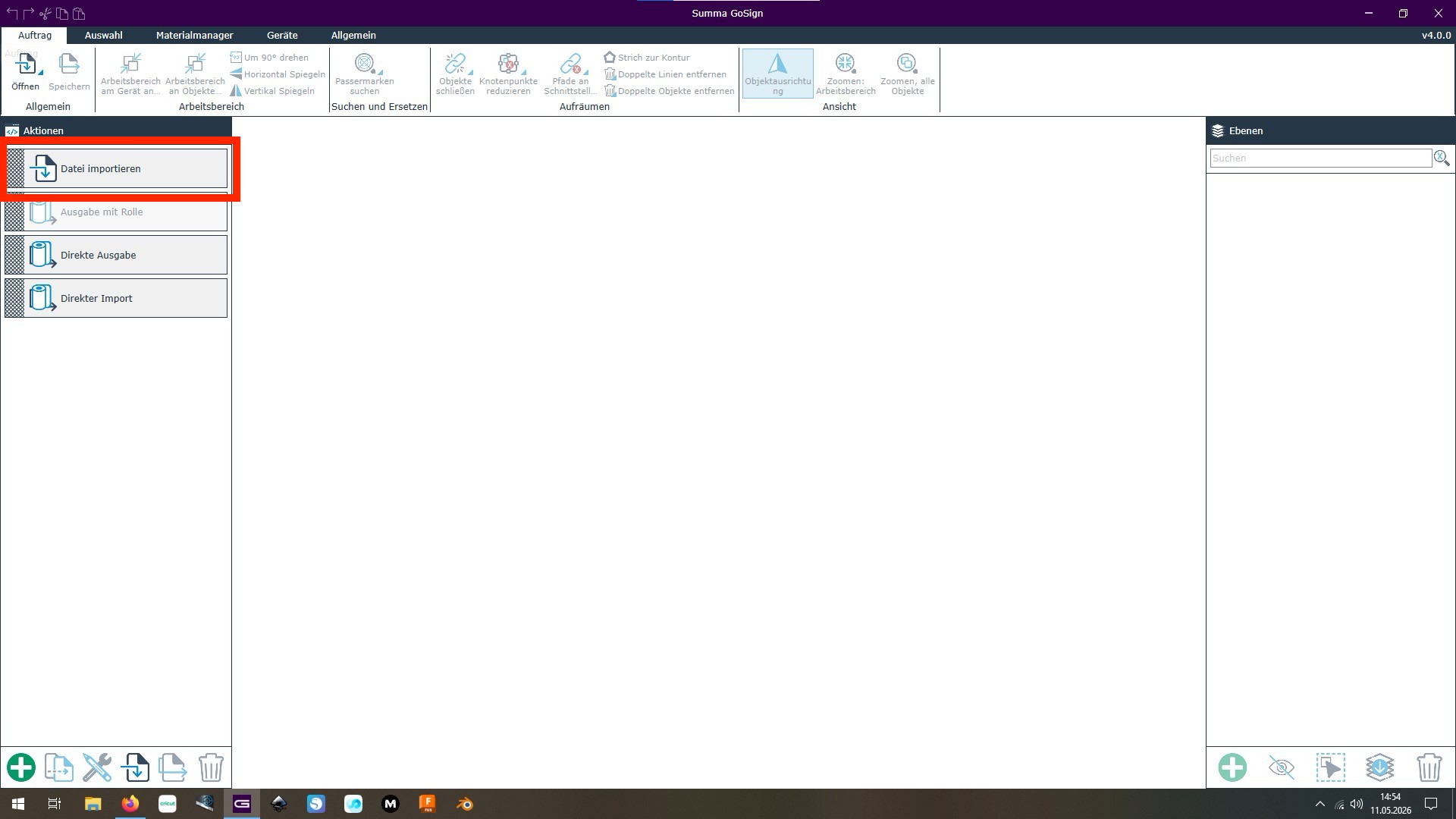
Open the "GoSign" software and import the .dxf file
-
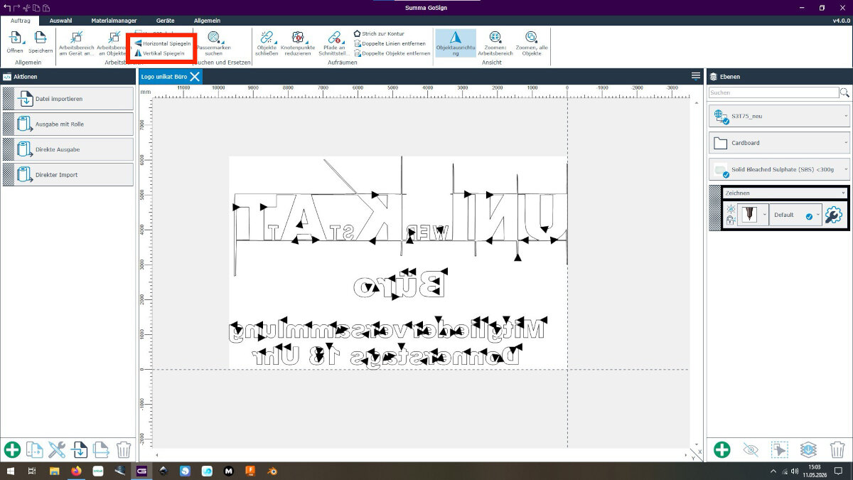
After importing, the .dxf file needed to be flipped since the sign will be glued to the inside of a glass door.
-
In the materials drop-down menu I selected the material: Self-adhesive
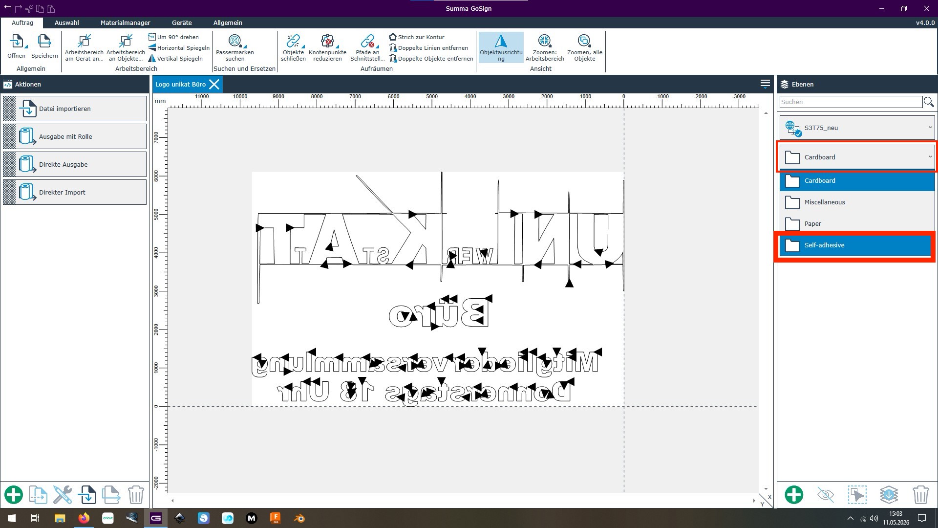
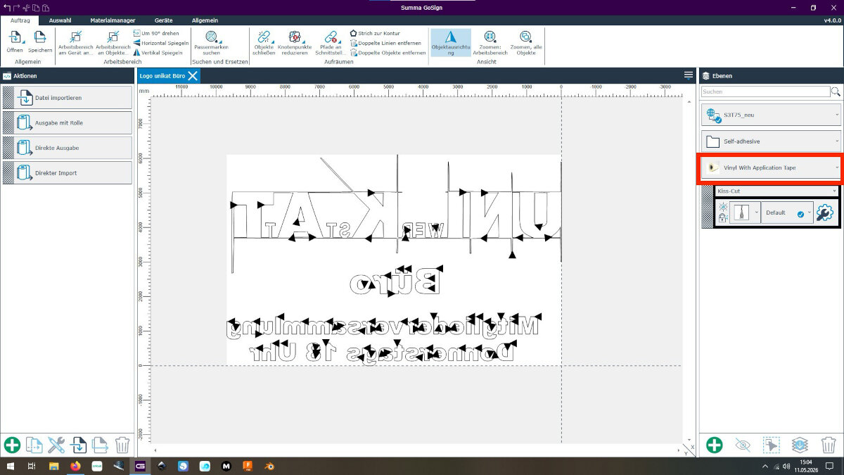
- In the second drop-down I chose: Vinyl With Backing
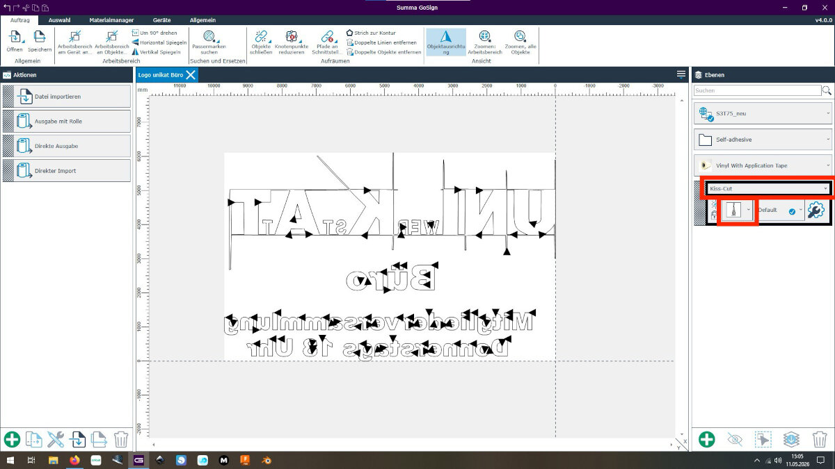
- For the cut type I selected "Kiss Cut" since I want the white backing material to remain uncut.
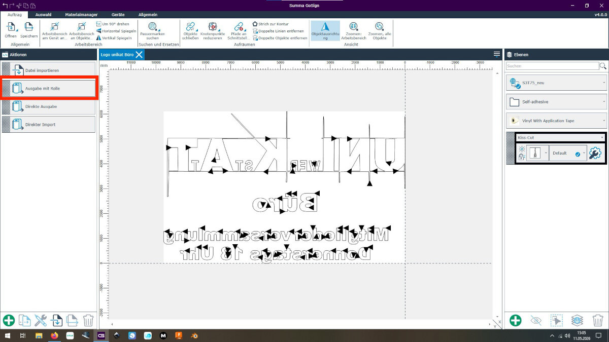
- Start the cut with: "Ausgabe mit Rolle" which is German for "Output on Roll"
Issues
Software: Design too large for the loaded material
The machine throws an error if the design is too large for the loaded material.
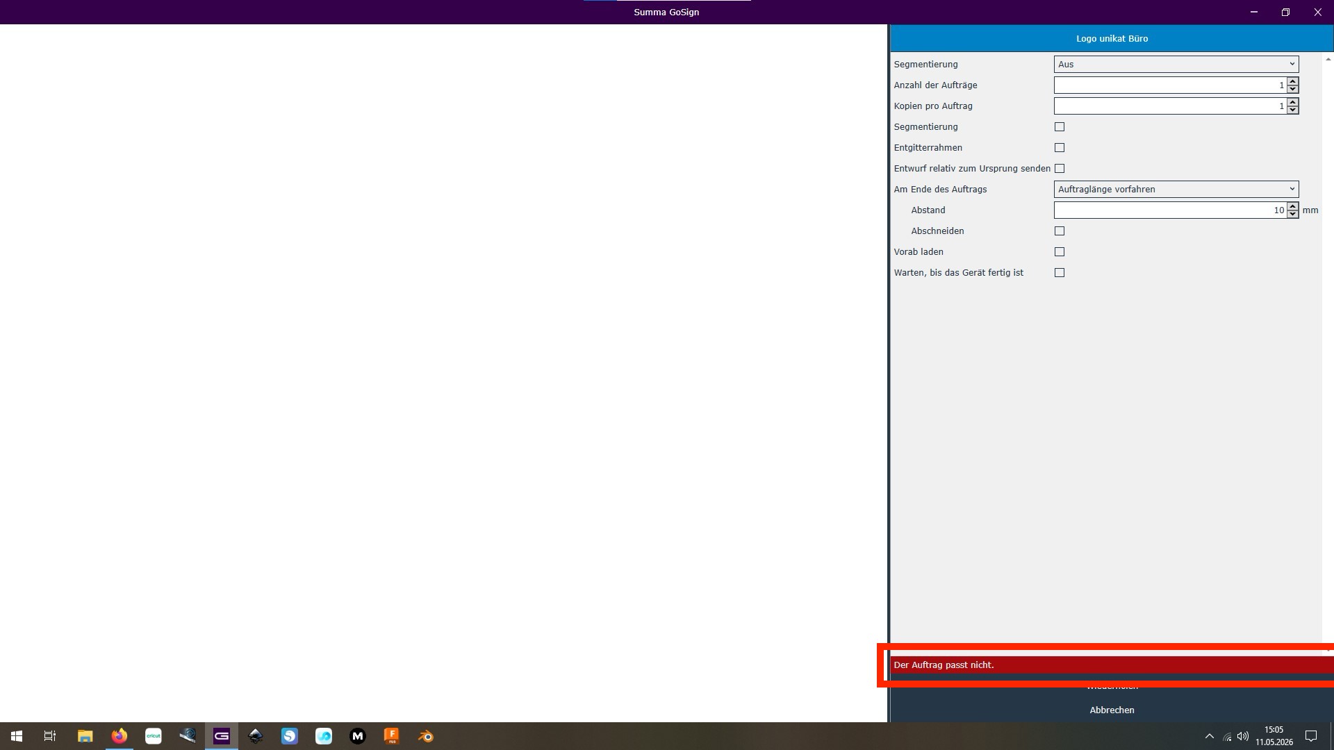
Fix: Reduce the design down to the size of the loaded material.
Hardware: dull tangential knife
At the time of writing the tangential knife was installed.
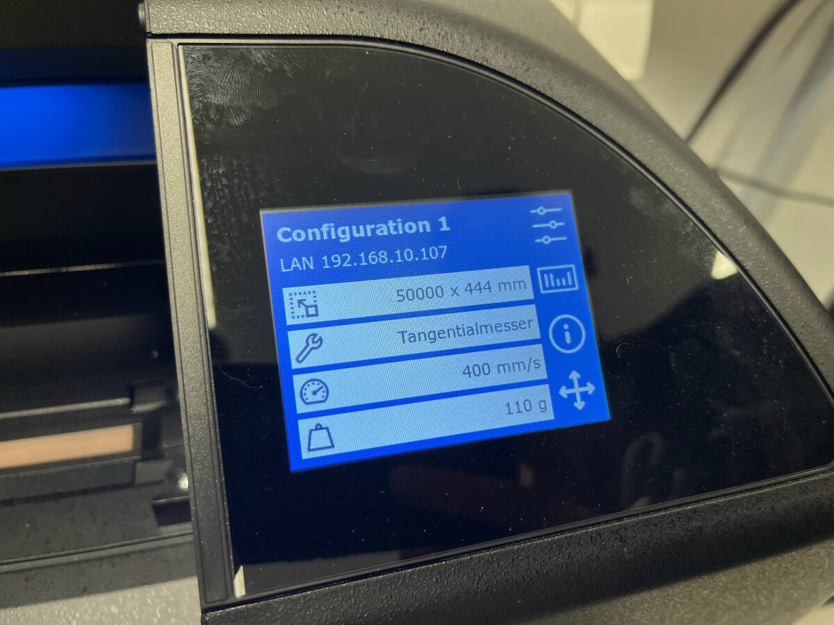
The first results we got were very rough, since the tip of the knife was broken. This was a bit tricky to debug since it is not really visible without a microscope.
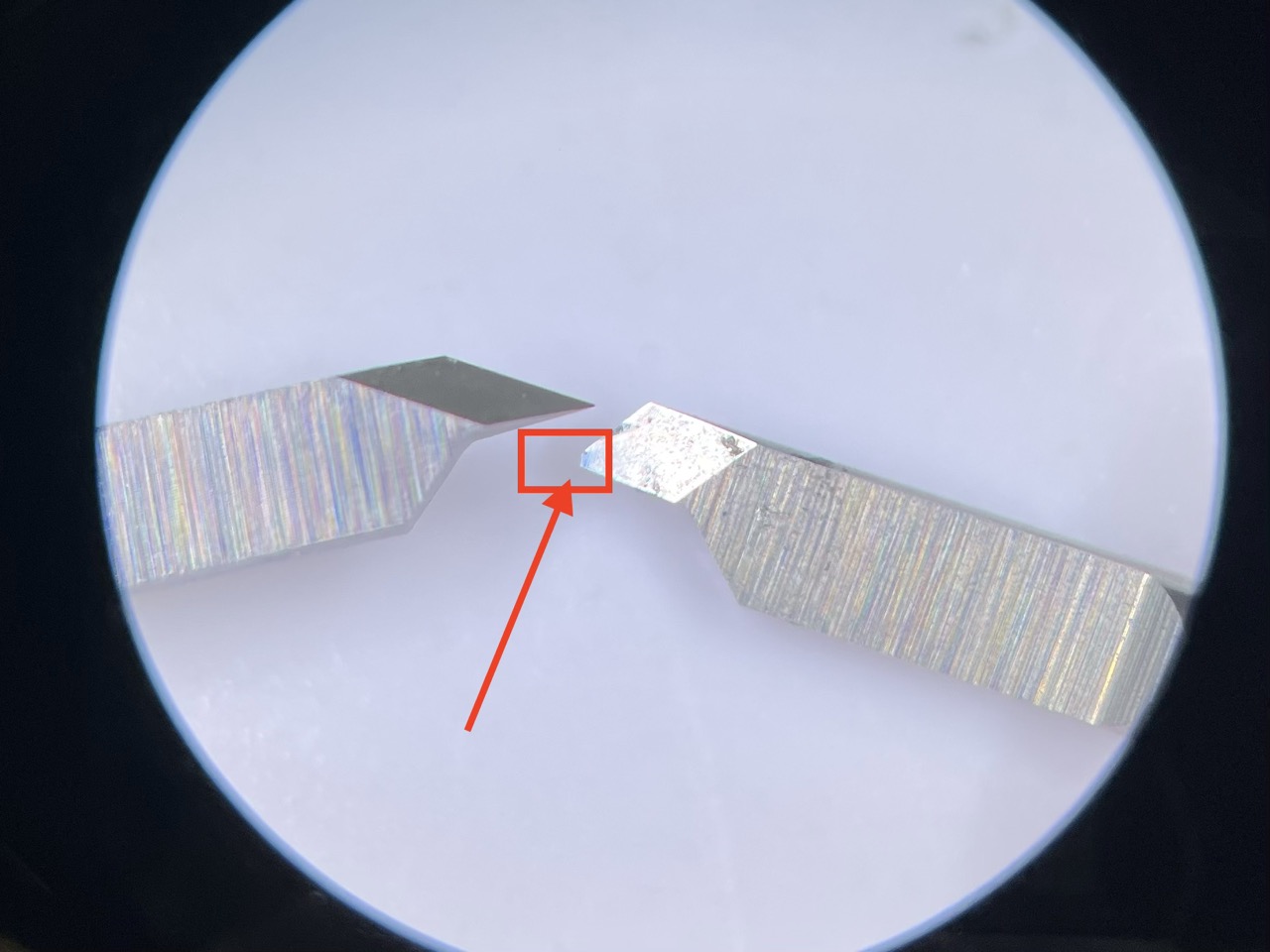
Left: sharp new undamaged tangential knife. Right: dull old knife with broken tip.
Fix: Replace the tangential knife.
Hardware: clogged bearings
While replacing the knife we found out, that the bearings were clogged.
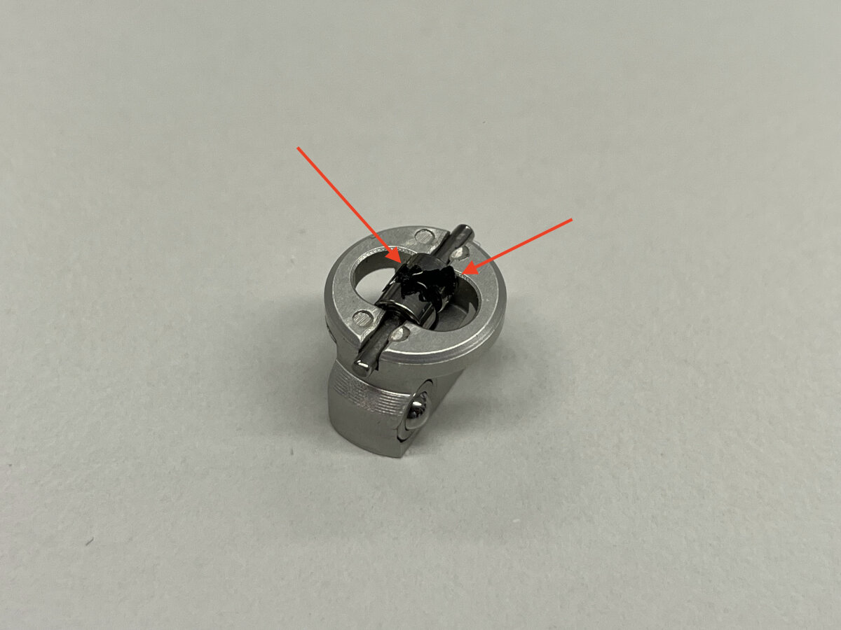 Fix: Clean or replace the bearings.
Result
After replacing the knife with a fresh one, the results got better but not perfect. After some research we switched from a 30° knife to a 60° knife.
OYEA - How to choose a cutting blade for cutting plotter?
After a couple of parameter changes, we managed to get decent results!
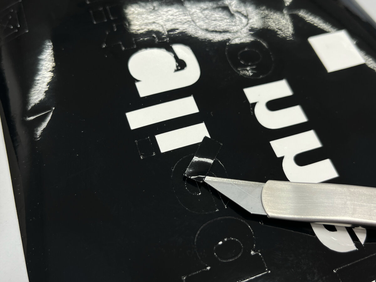
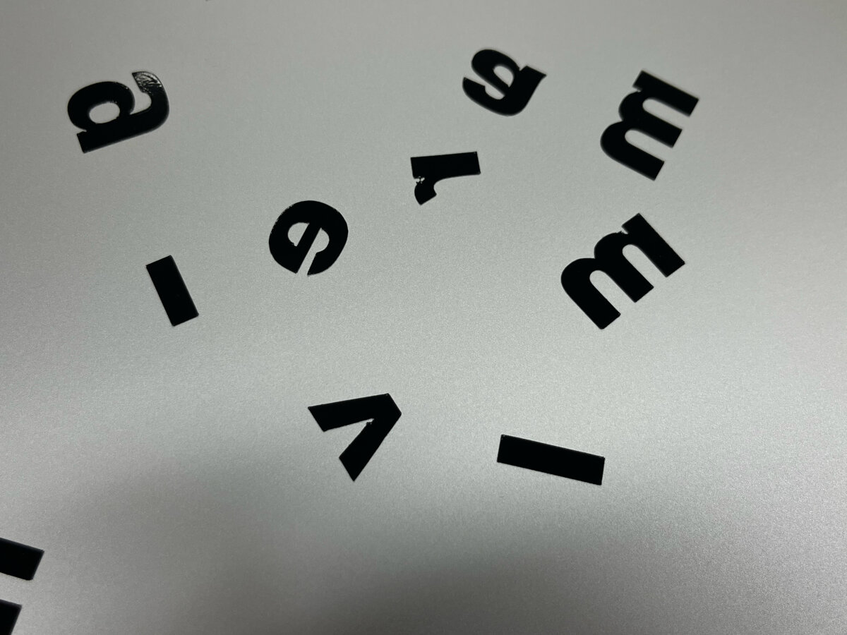
Final result: Vinyl letters glued onto an aluminum plate.
© 2026 Richard Draxler – Creative Commons Attribution Non Commercial
Source code hosted at gitlab.fabcloud.org