
Fab Academy 2025.
We make, modify and share a new variant of the open source machine.
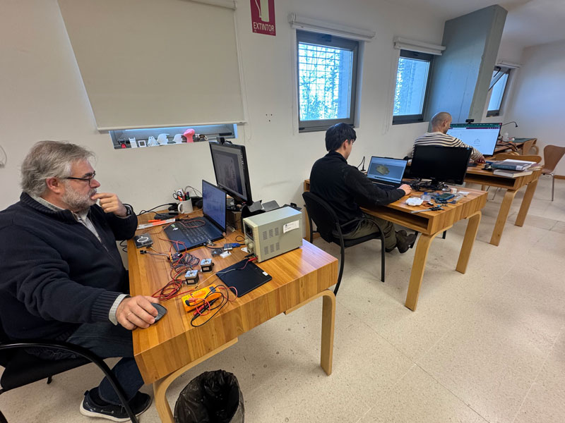
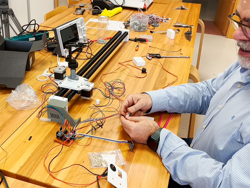
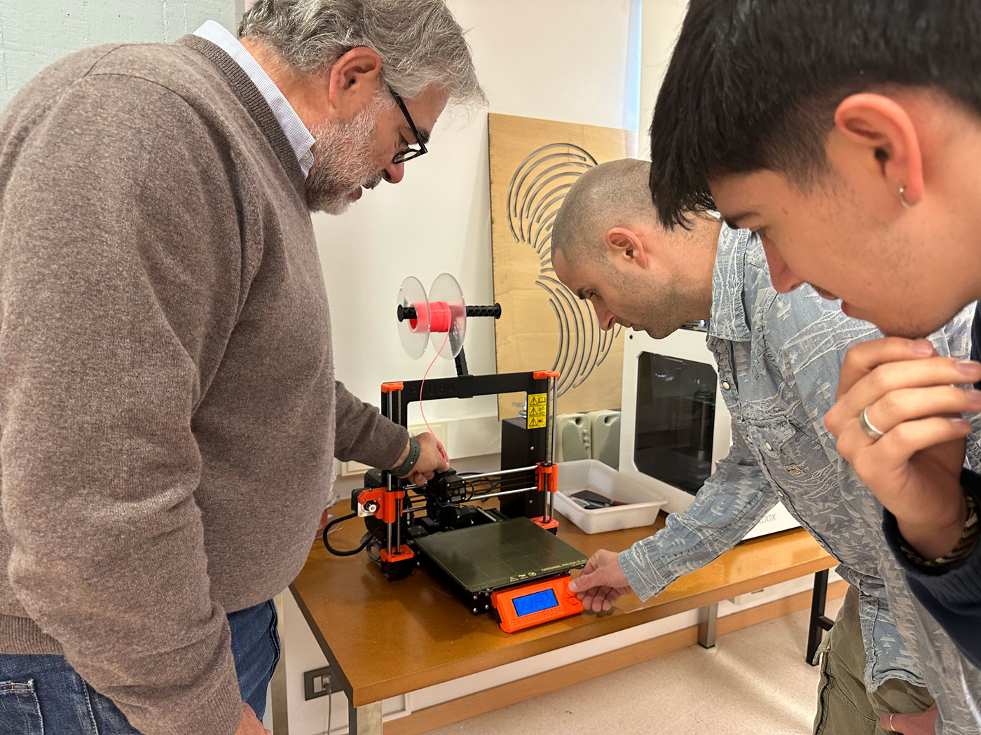
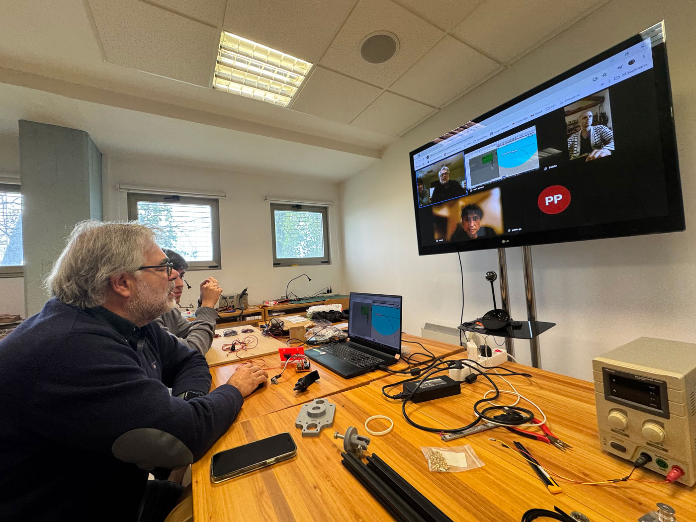
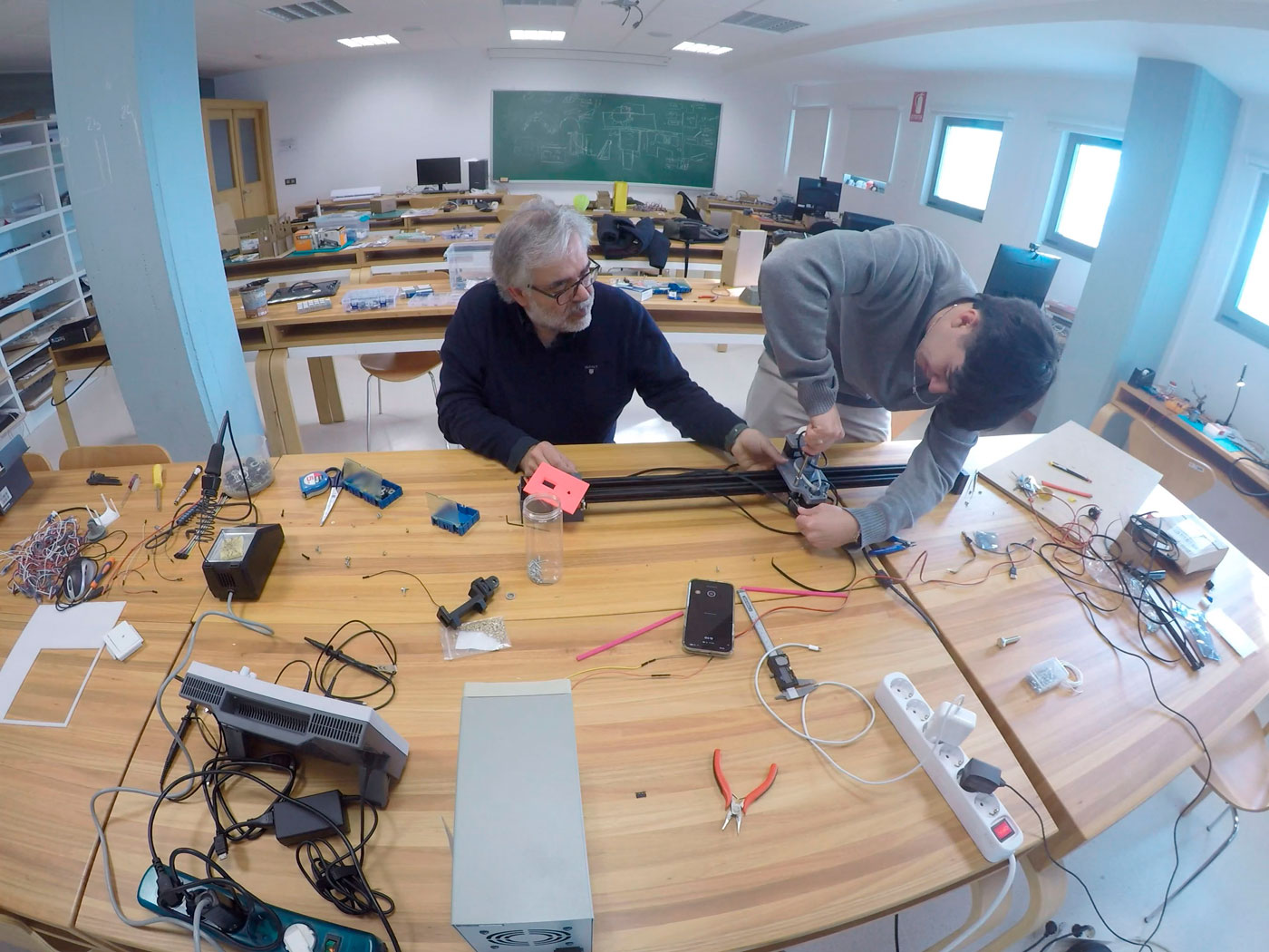
In the morning following Neil’s class, Thursday April 10th, we started preparing the project for our machine at FabLab ETSAC in Coruña.
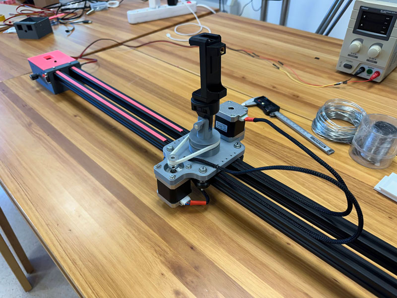
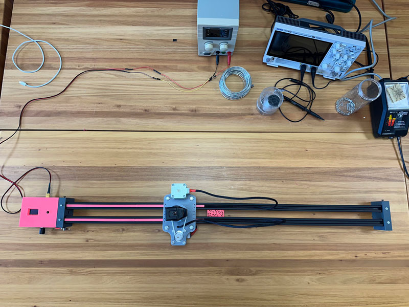
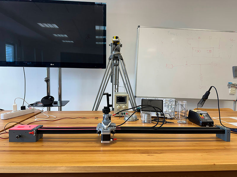
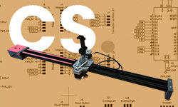
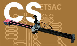
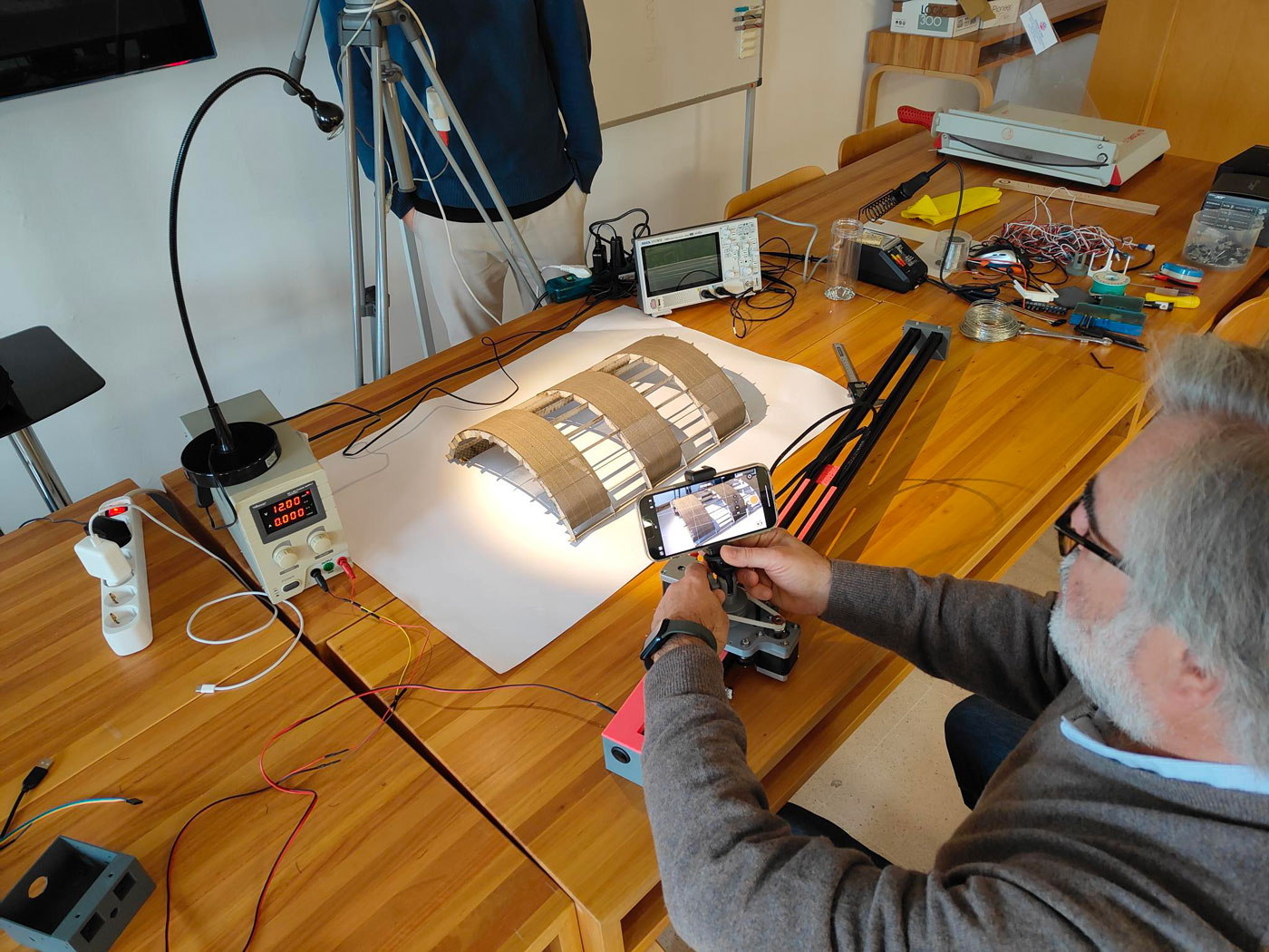
As a group, we designed a motorized camera slider aimed at providing architecture students with an accessible tool to record their models, facilitating the presentation of their final projects. The goal for this week was to build a system capable of mounting a mobile phone or camera and recording along two axes: one linear axis, where the user can define the start and end points of the travel path, and a rotational axis, which allows for adjusting the angle of camera rotation. The system also permits setting the speed and total duration of the defined path.
Modifications in the original project
We make, modify and share a new variant of the open source machine.
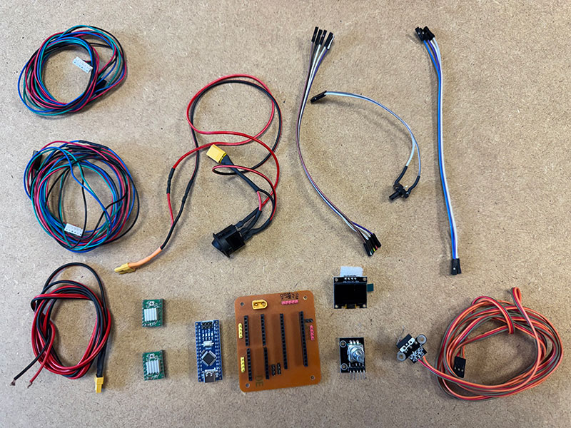
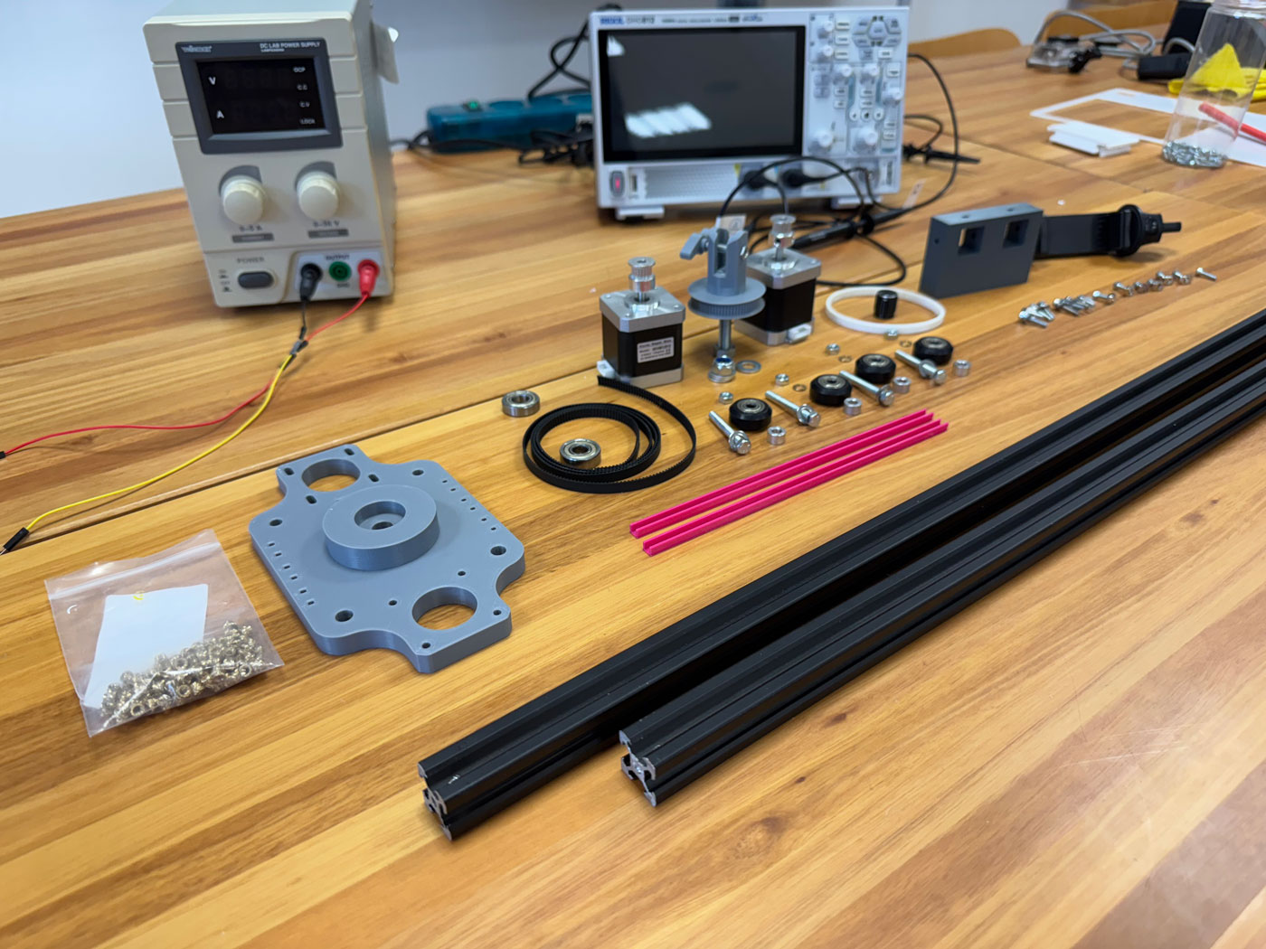
After exploring several repositories of camera sliders, we found two particularly relevant: Rztronics’ Homemade Motorized Camera Slider and ProKnow’s Building a Motorized Camera Slider. Based on the documentation shared by these creators, we analyzed the list of components and verified local availability for equivalent or compatible parts.
From there, we implemented the following design changes:
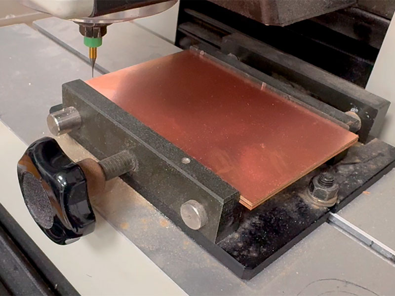
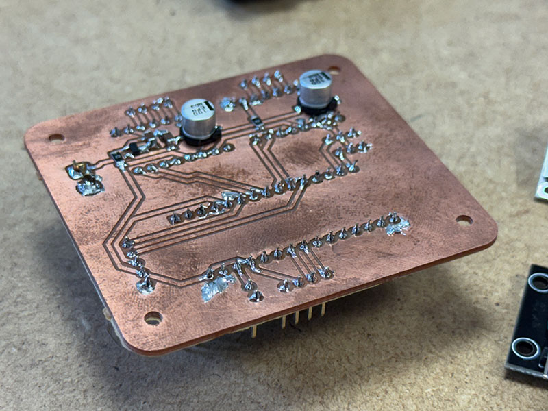
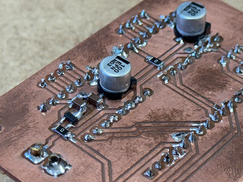
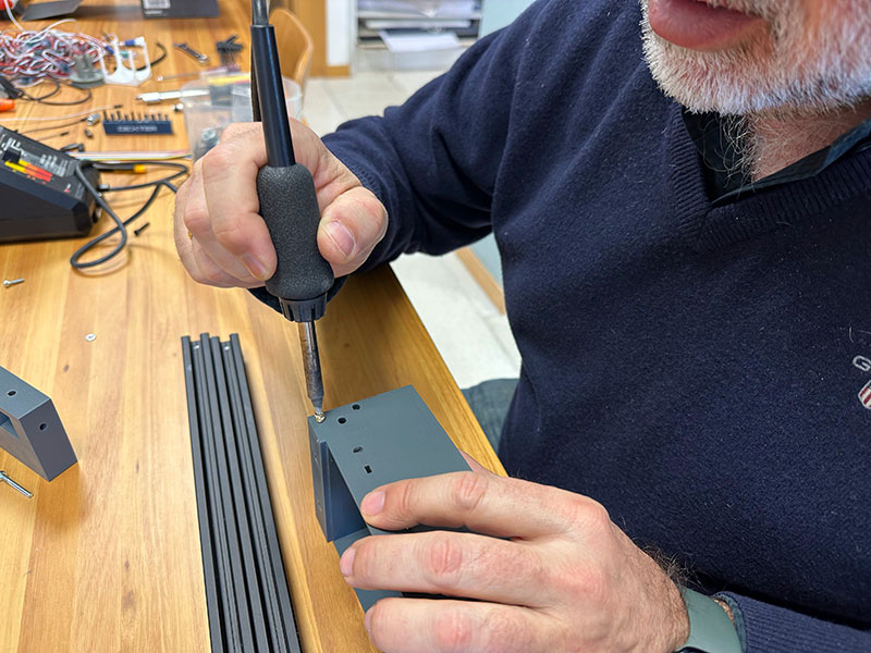
- Designed a custom PCB in KiCAD to be milled using our Roland machine and soldered all components manually.
- Developed parametric 3D models for printable components:
- - The enclosure box
- - A snap-fit lid
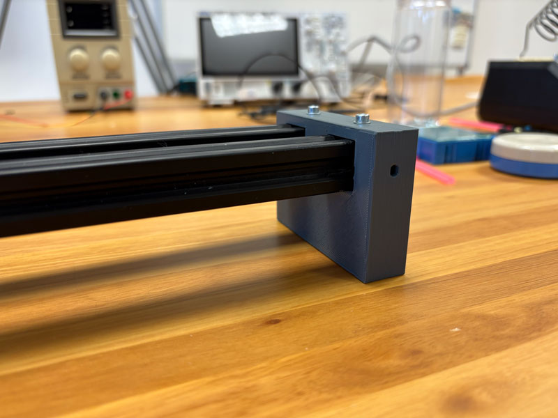
- - Rail-end supports, featuring inserts for future structural reinforcements
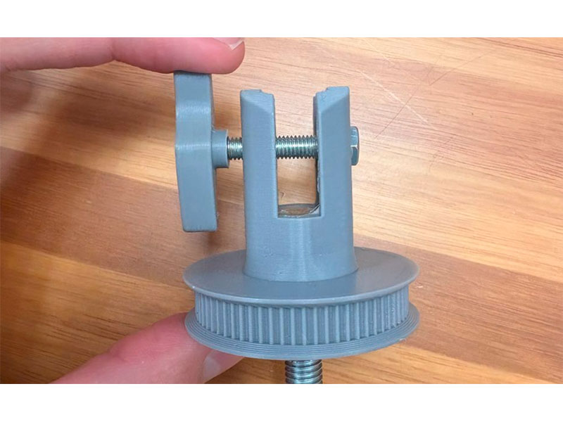
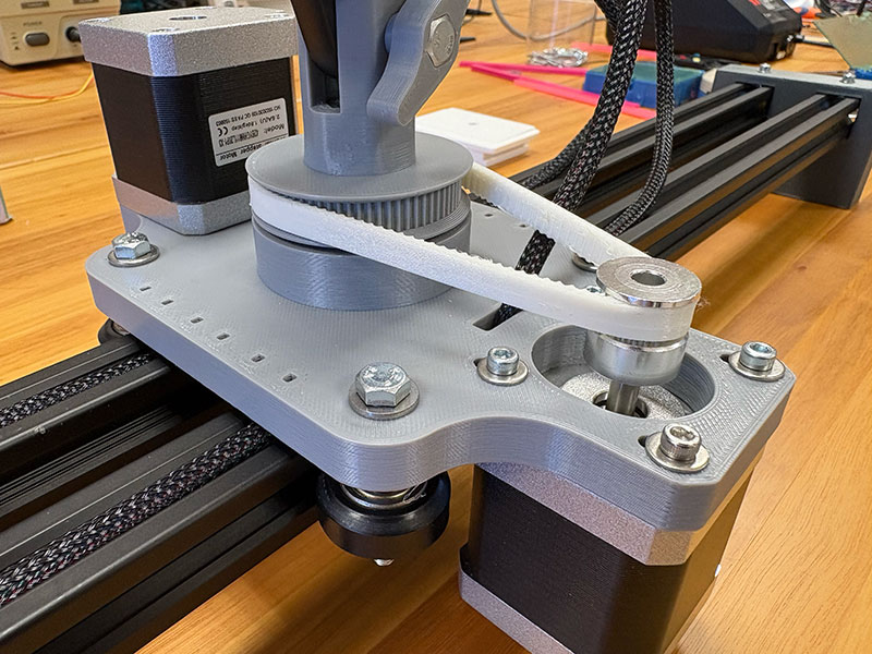
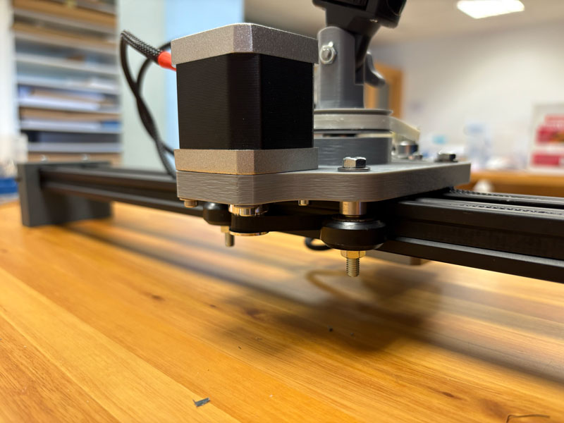
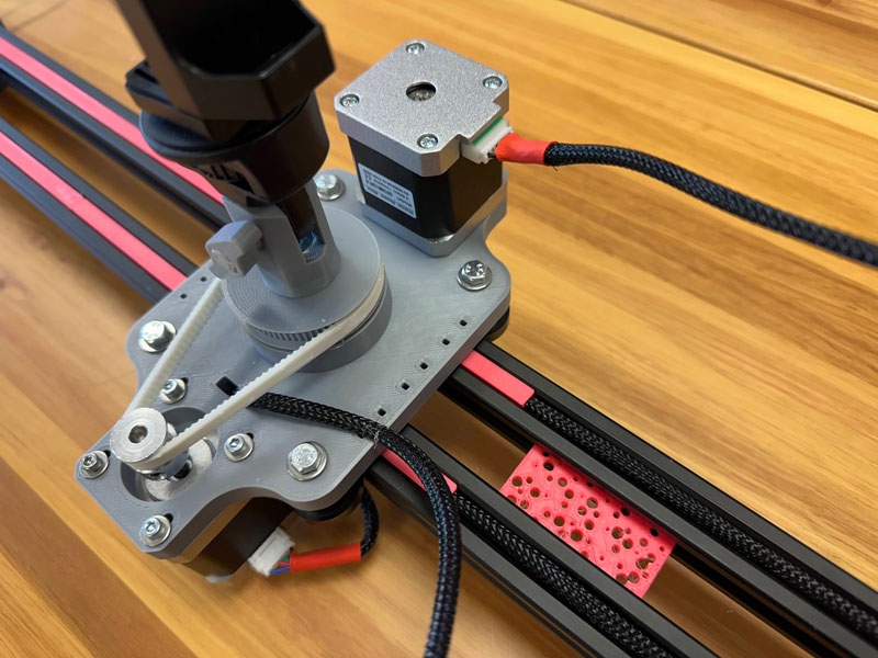
- Rigidly coupled the gear responsible for rotating the vertical camera shaft with the camera support structure to improve overall stiffness.
1 Group
Belt, Enclosure and 3D Printed Parts
Group information
- Category: Assembly
- Difficulty: Medium
- Build date: 19 April, 2025
- Build time: 18 hours
Belt, Enclosure and 3D Printed Parts
The timing belt was designed in OpenSCAD using a customizable Thingiverse script, allowing for adjustment of tooth count, profile, thickness, and width. The belt was printed in flexible TPU filament.
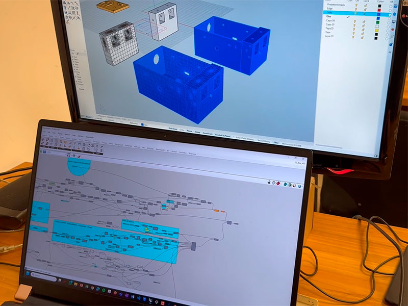
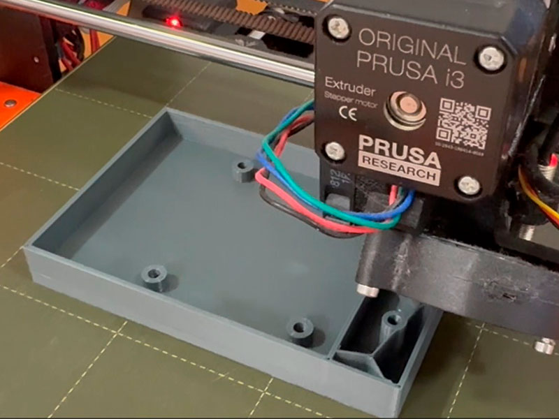
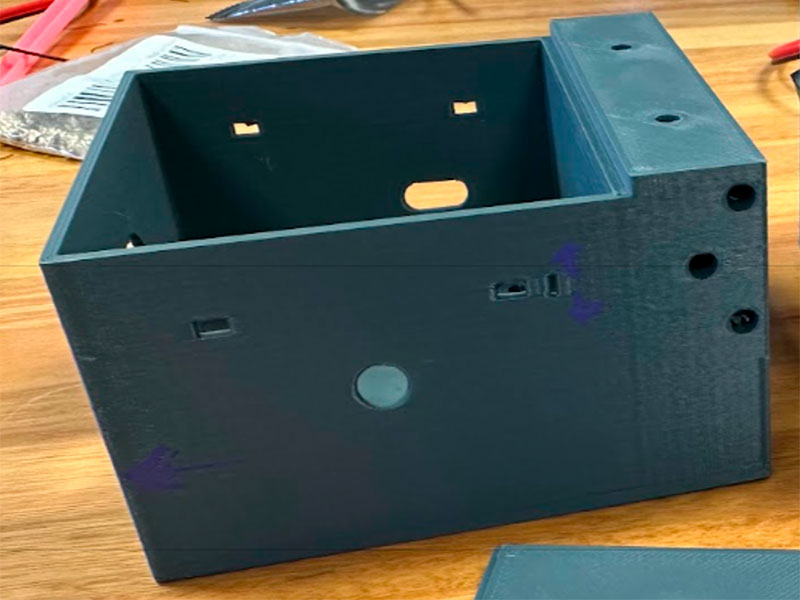
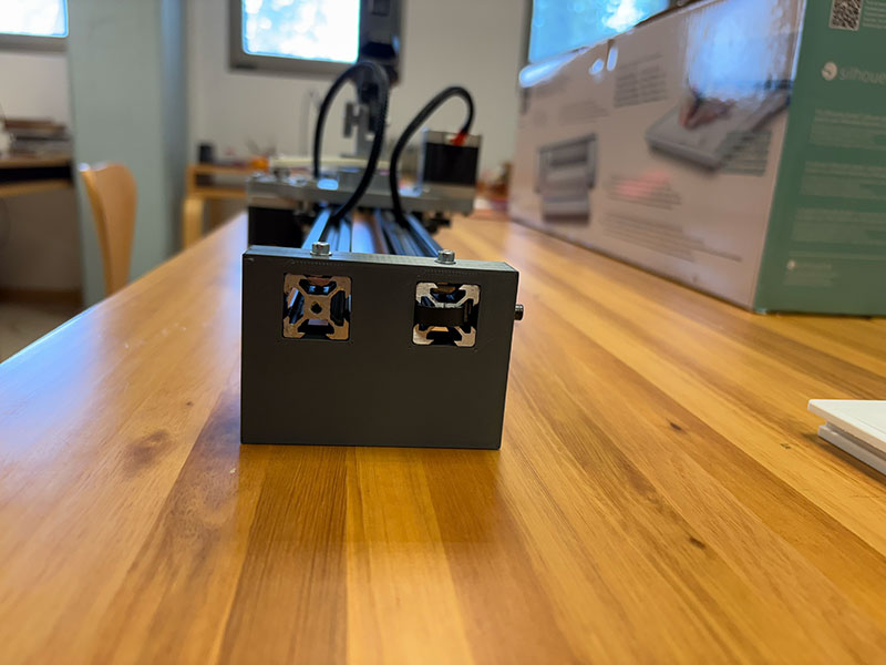
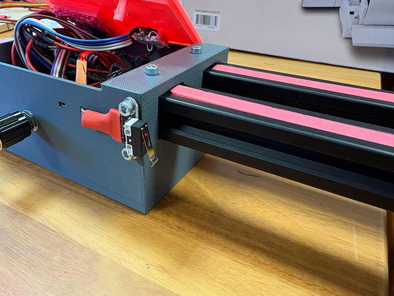
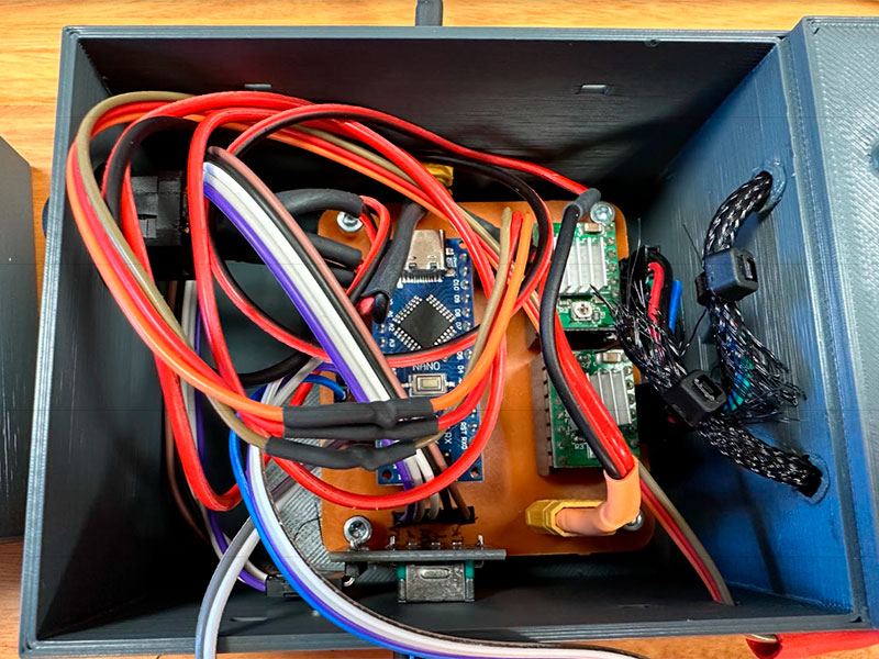
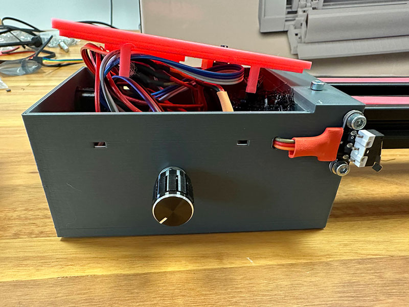
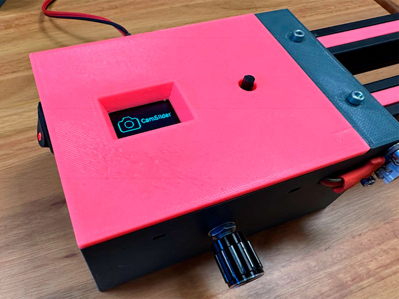
The control enclosure was parametrically modelled in Grasshopper and 3D printed. It houses the PCB, an OLED display, a reset button (top), a power button (side), and a potentiometer (front) to manually configure start/end positions and camera angle.
Cable routing holes and mounting inserts were also integrated. Additional parts such as motor mounts and phone supports were adapted to the bearings available at the lab.
Description of Groups Components
| Type | Component | Amount | Description |
|---|---|---|---|
| Printed Parts | Belt GT2 | 1 | TPU filament. (110 teeth, 2.5 mm thick, 9 mm height) |
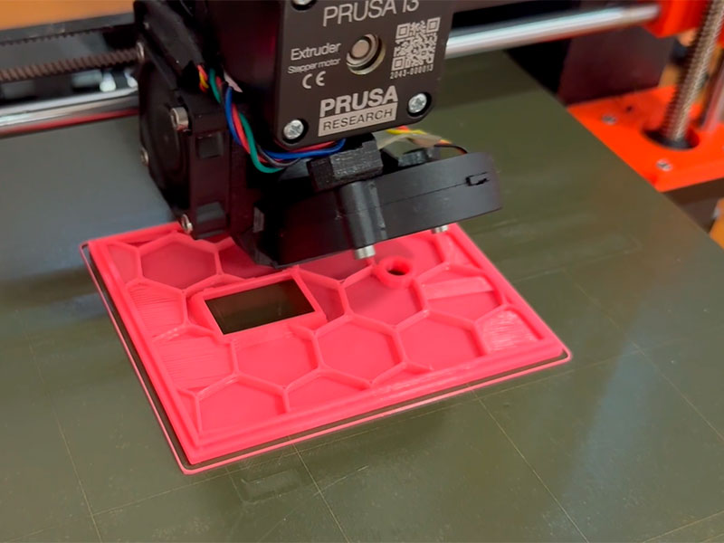
| Printed Parts | Box lid | 1 | PLA filament |
| Printed Parts | Spacer | 1 | PLA filament |
| Hardware | Insert nuts | 6 | M3 |
| Hardware | Screws | 6 | M3 (5 mm and 6 mm) |
| Electronics | Rotary encoder | 1 | |
| Electronics | 0.96" I2C OLED | 1 | |
| Electronics | On/Off Button | 1 | |
| Electronics | Reset Button | 1 | |
| Printed Parts | PCB spacer | 4 | PLA filament |
| Printed Parts | Rail spacer | 1 | PLA filament |
2 Group
Frame Structure
Group information
- Category: Assembly
- Difficulty: Medium
- Build date: 11 April, 2025
- Build time: 3 hours
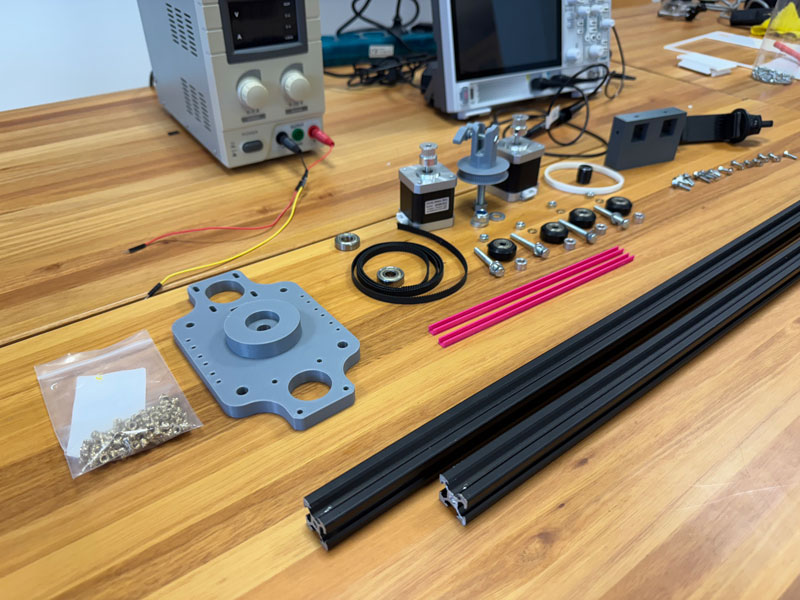
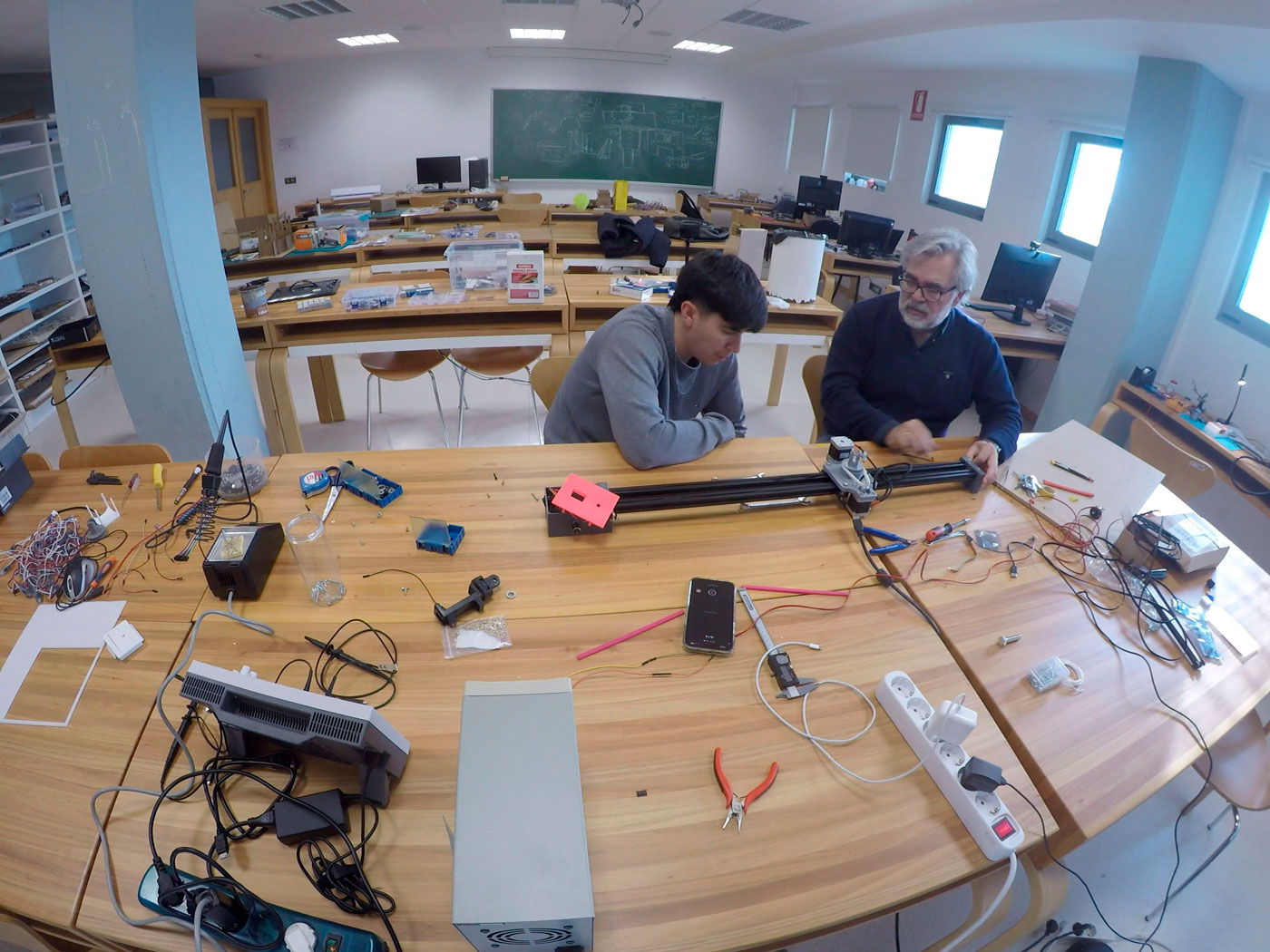
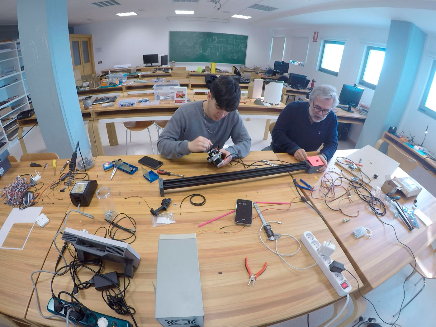
Structure assembly
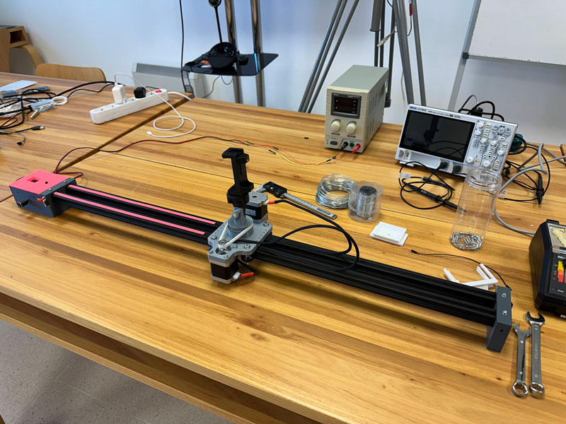
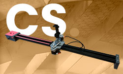
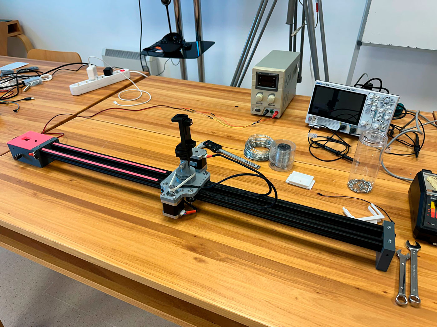
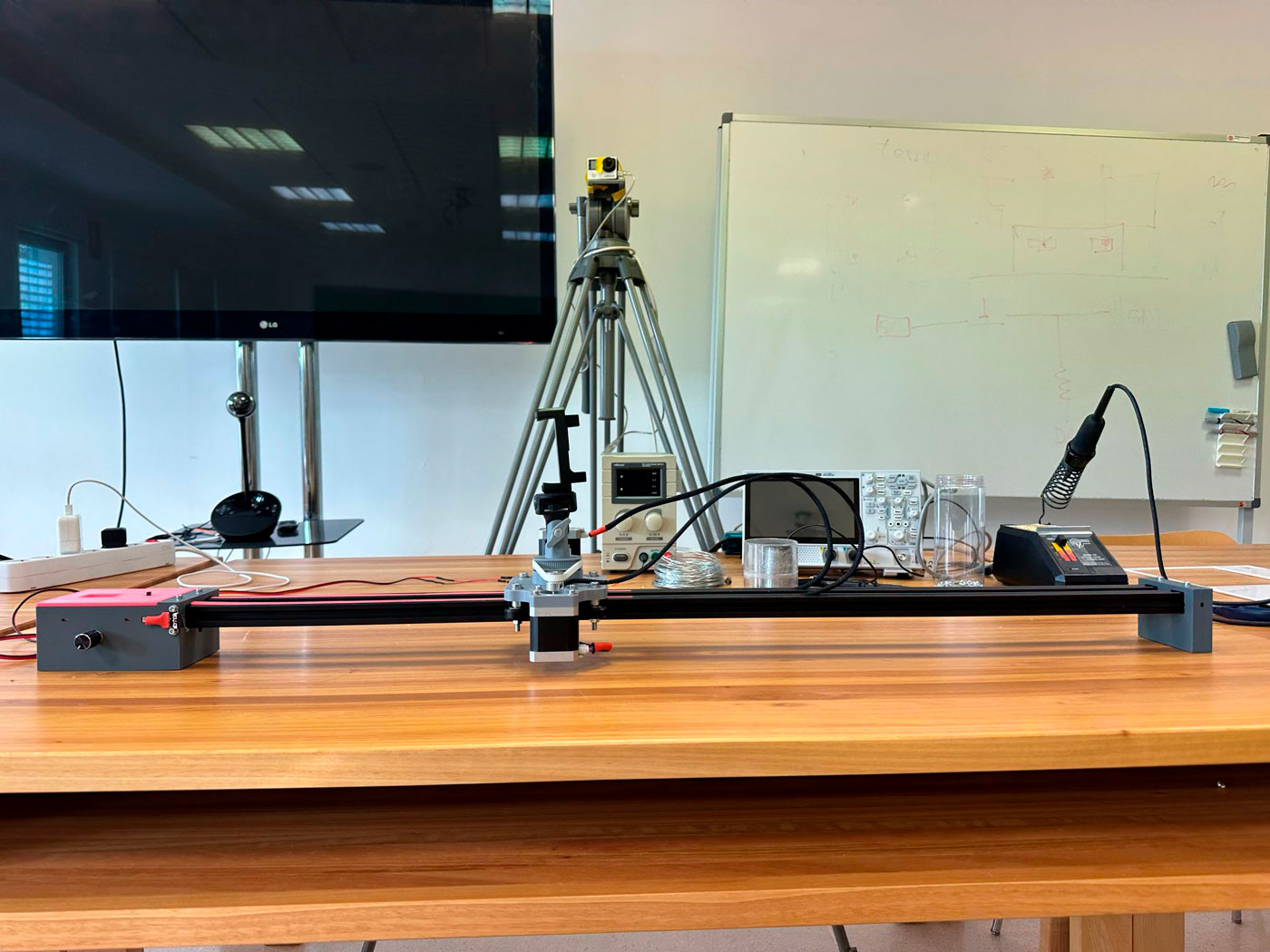
The frame consists of two end supports connected by 20x20 mm aluminium extrusion rails. A camera platform slides along these rails, driven by two stepper motors mounted on a 3D-printed base.
Description of Groups Components
| Type | Component | Amount | Description |
|---|---|---|---|
| Frame | V - Slot 20260 Aluminum Extrusion Profile | 2 | 860 mm |
| Printed Parts | Support box | 1 | PLA filament |
| Printed Parts | Remote support | 1 | PLA filament |
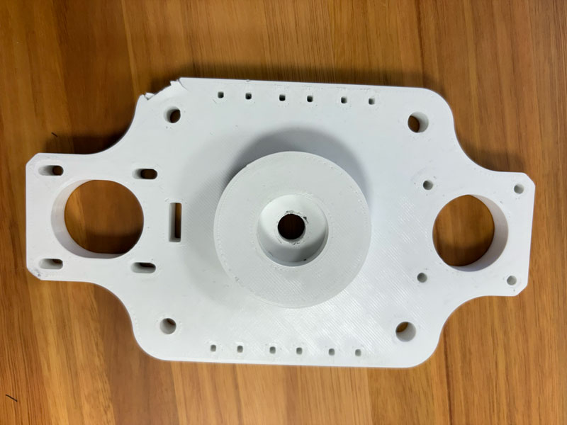
| Printed Parts | Sliding Base | 1 | PLA filament |
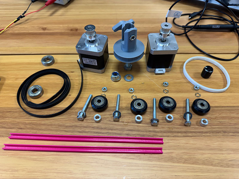
| Printed Parts | Gear and camera support | 1 | PLA filament |
3 Group
Motion Mechanics

Group information
- Category: Assembly
- Difficulty: Medium
- Build date: 10 April, 2025
- Build time: 4 hours
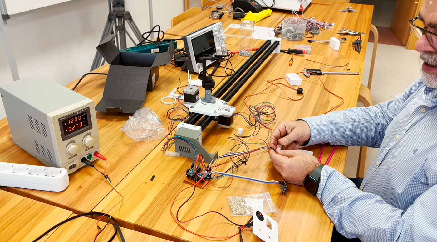
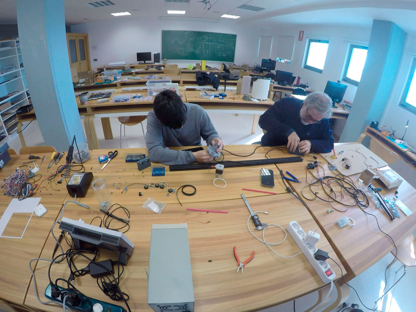
Motion Mechanics
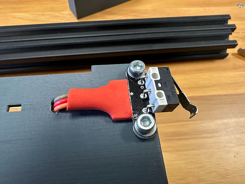
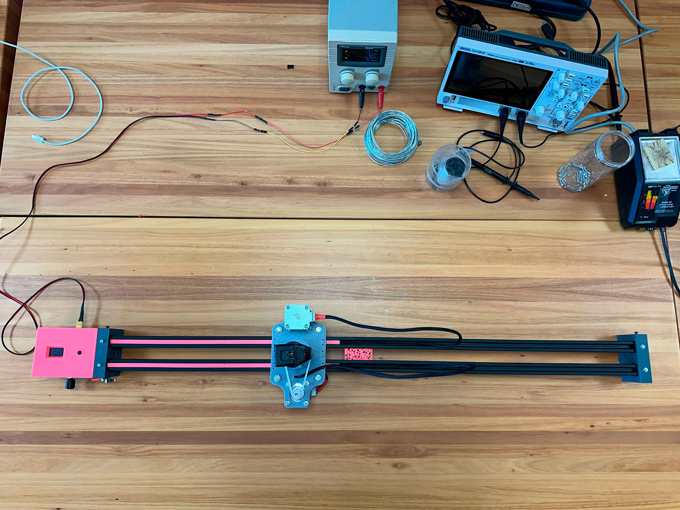
Motion is enabled by two stepper motors: one for linear displacement along the rails via a GT2 belt, and the second for rotational control using a PLA printed gear. A limit switch is used to define the initial position.
Description of Groups Components
| Type | Component | Amount | Description |
|---|---|---|---|
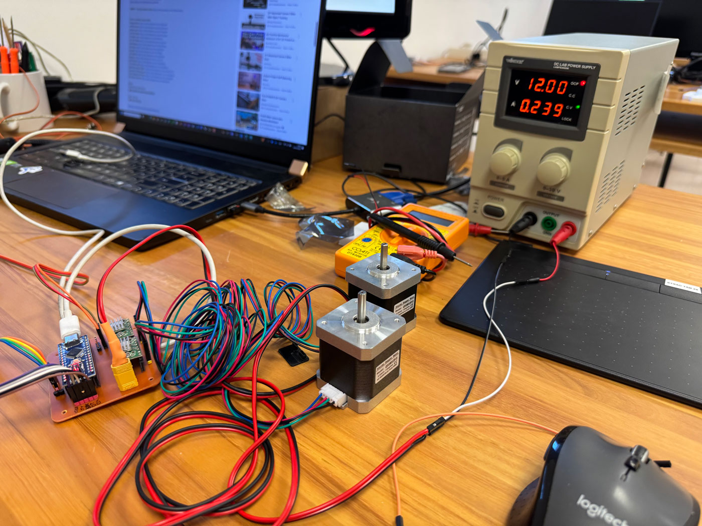
| Electronics | Nema 17 Stepper Motor | 2 | 2.5A, 1.8°/step |
| Hardware | GT2 Belt | 1 | 1000 mm |
| Hardware | Delrin V-wheel | 4) | V-guide system |
| Electronics | Limit switch | 1 |
4 Group
Electronics and PCB Design
Group information
- Category: Assembly
- Difficulty: Medium
- Build date: 10 April, 2025
- Build time: 10 hours
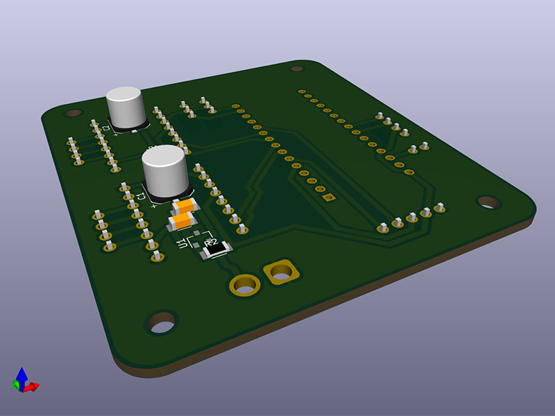
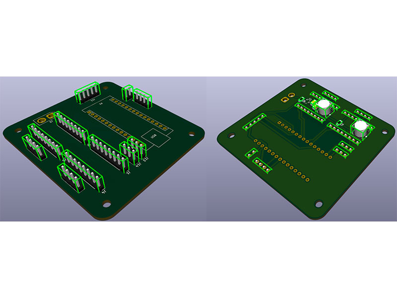
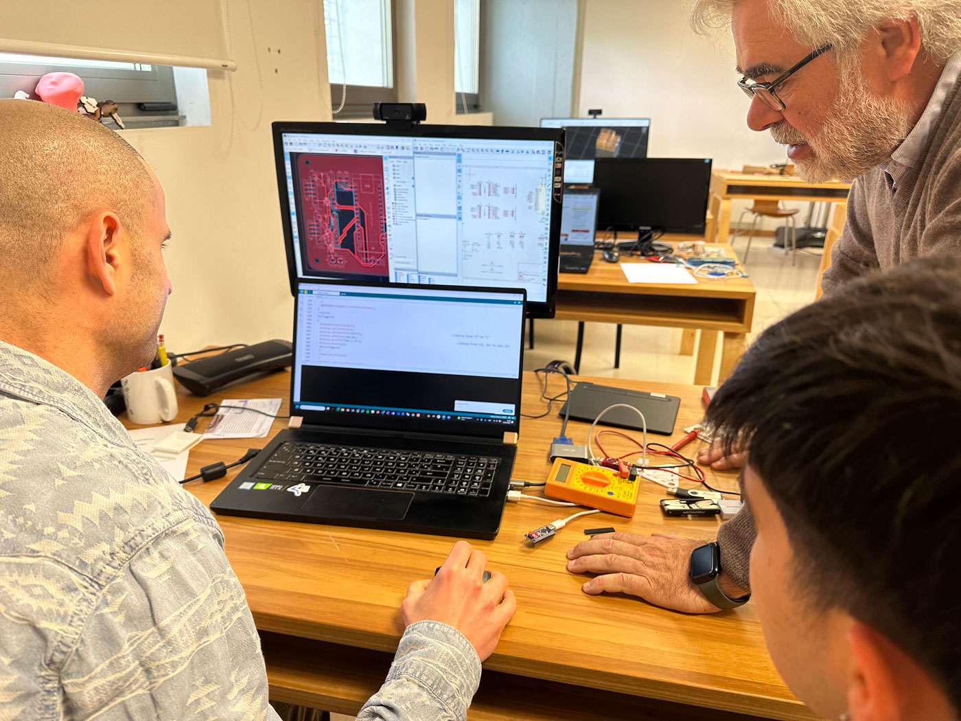
Electronics and PCB Design
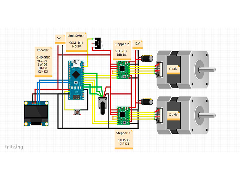
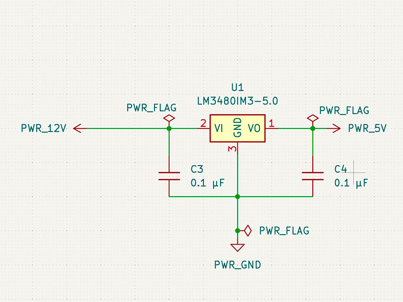
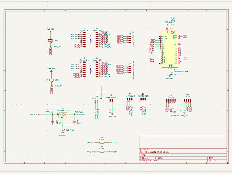
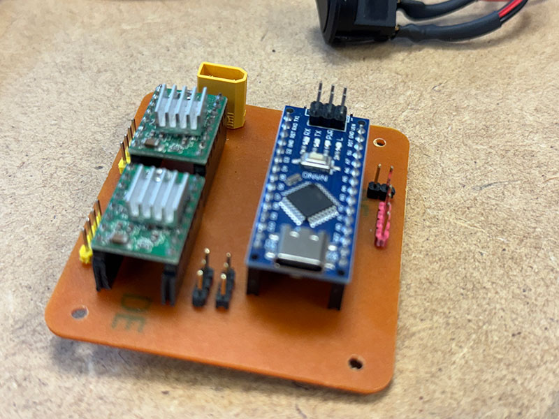
We redesigned the PCB in KiCAD. To regulate the 12V input down to 5V, we used an LM3480IM3-5.0 voltage regulator, avoiding the need for dual power sources.
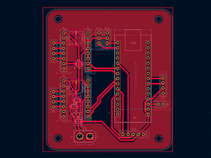
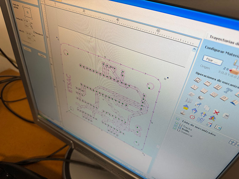
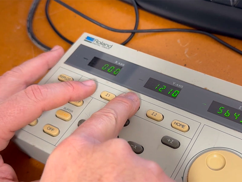
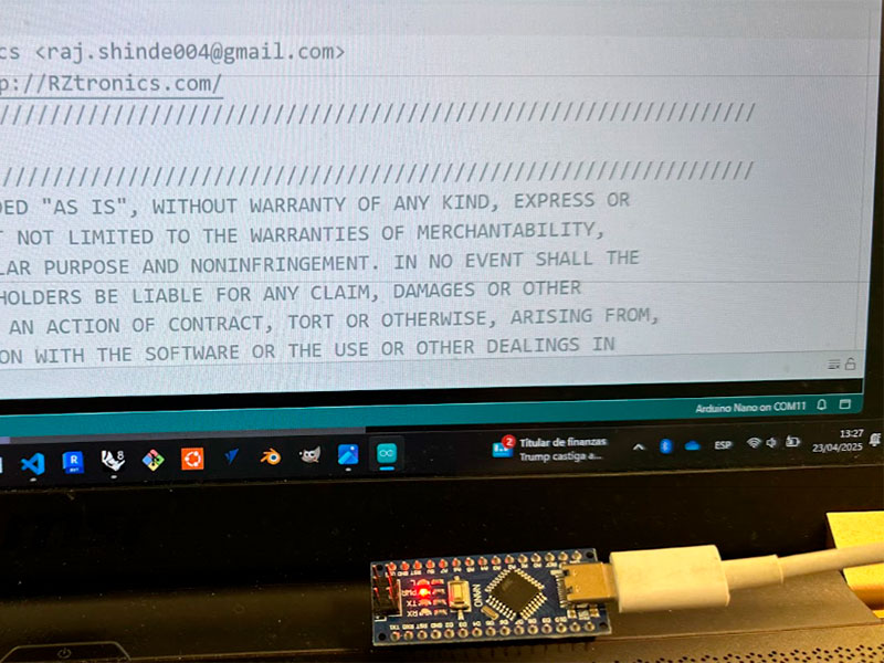
The controller is an Arduino Nano connected to two stepper drivers. PCB manufacturing was done using VCarve and a Roland CAMM PNC-2500. The process is documented in the week 8 group page.
Description of Groups Components
| Ref. | Value | Footprint | Quantity |
|---|---|---|---|
| C1, C2 | 100 µF | CP_Elec_100uF_Panasonic_EEE-FN1E101UL | 1 |
| C3, C4 | 0.1 µF | C_1206 | 2 |
| R1, R2 | 0 Ohm | R_1206 | 2 |
| U1 | LM3480IM3-5.0 | SOT-23-3 | 1 |
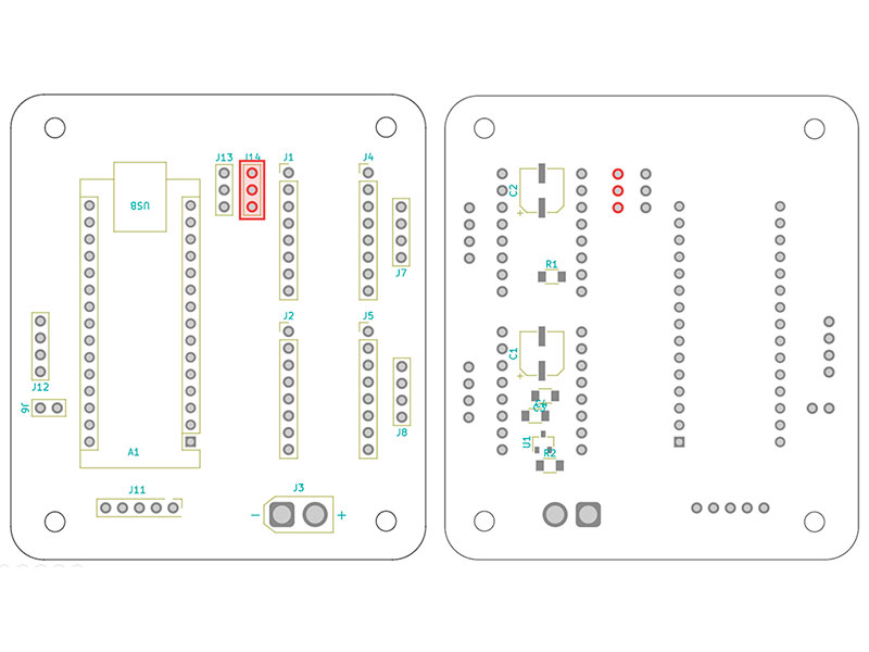
| A1 | Arduino_Nano_v3.x | Arduino_Nano | 1 |
| J1, J2 | Stepper 2L, Stepper1 L | PinHeader_01x08_P2.54mm_Vertical_THT_D1mm | 2 |
| J3 | Power Switch | AMASS_XT30U-M_1x02_P5.0mm_Vertical | 1 |
| J4, J5 | Stepper 1R, Stepper 2R | PinHeader_01x08_P2.54mm_Vertical_THT_D1mm | 2 |
| J6 | Reset Button | PinHeader_01x02_P2.54mm_Vertical_THT_D1mm | 1 |
| J7, J8, J12 | Connector to Motor 2Y, Connector to Motor 1X, OLED | PinHeader_01x04_P2.54mm_Vertical_THT_D1mm | 3 |
| J11 | Encoder | PinHeader_01x05_P2.54mm_Vertical_THT_D1mm | 1 |
| J13, J14 | EndStopRight, EndStopLeft | PinHeader_01x03_P2.54mm_Vertical_THT_D1mm | 2 |
5 Group
Software
Group information
- Category: Electronics
- Difficulty: Easy
- Build date: 10 April, 2025
- Build time: 2 hours
- Files: Download
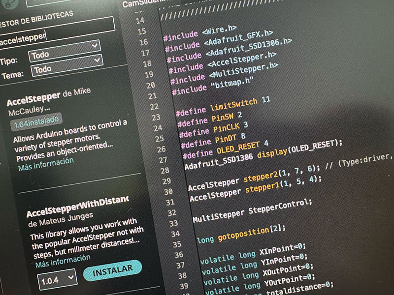
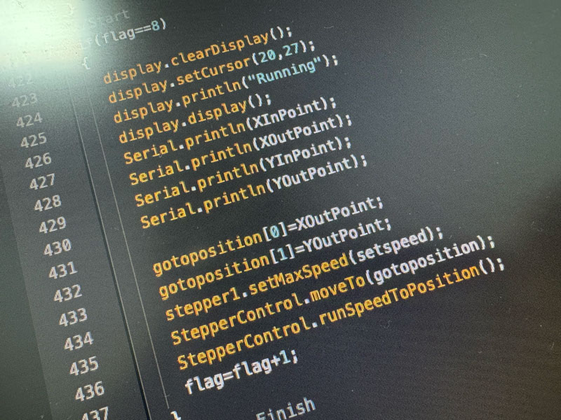
Software
We used the code provided by Pro Know in their shared drive: “DIY Motorized Camera Slider – Google Drive”. We did not modify the code, only reviewed pin assignments. In the future, we plan to add a third motor for tilt control, but due to time constraints, our current focus is documenting and presenting a working prototype.
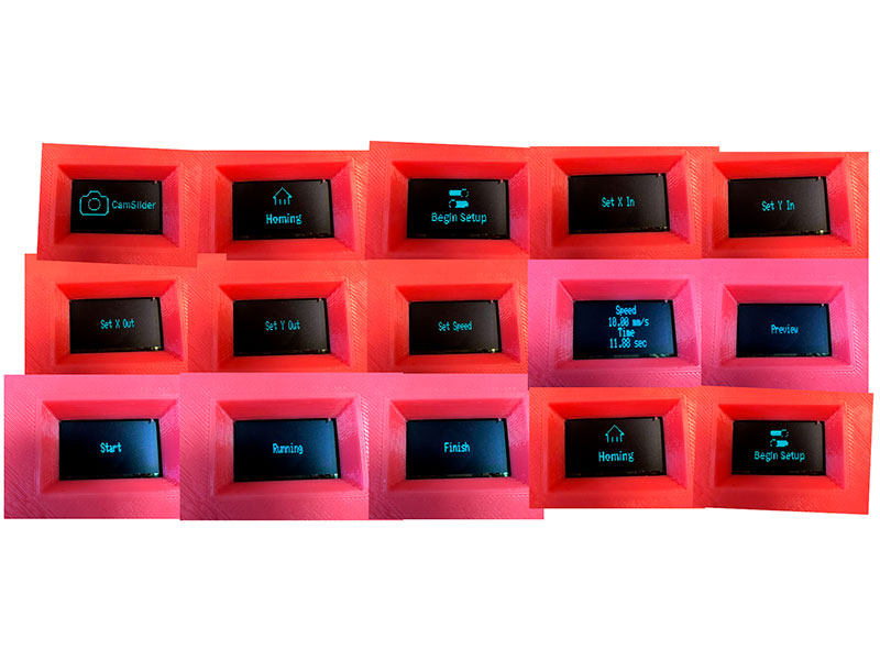
Camslider Workflow
1. Power ON – Homing
2. Set X start
3. Set Y start
4. Set X end
5. Set Y end
6. Preview
7. Configure speed or duration
8. Run
9. End
10. Reset button – return to home
6 Group
Assembly

Group information
- Category: Assembly
- Difficulty: Easy-Medium
- Build date: 22 April, 2025
- Build time: 6 hours
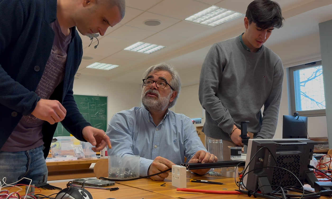
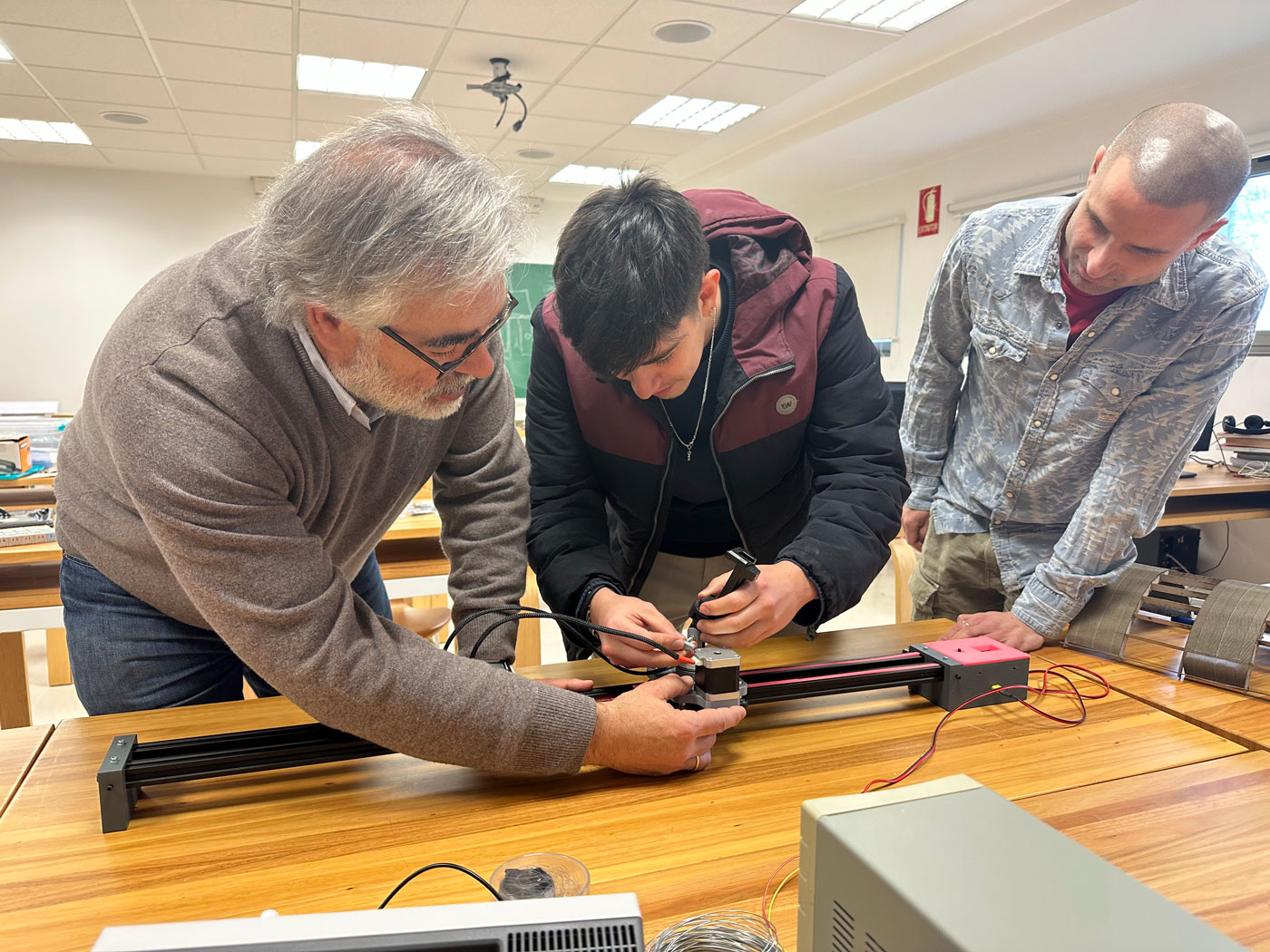
Final Assembly
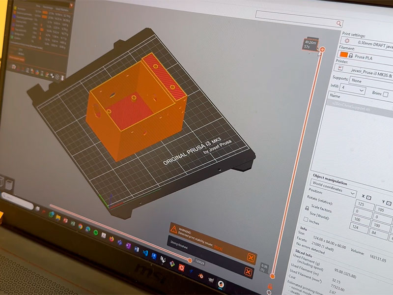
During final assembly, we had to adjust several design features. The control box was initially too tight around the PCB, leaving insufficient room for internal wiring. We solved this by increasing the box size by 25 mm (X-axis) and 5 mm (Z-axis). Snap-fit tabs on the lid were also too rigid and prone to breaking; we refined their geometry to allow slight flexibility.
We also relocated the power button for better access. Once adjustments were made, we re-meshed and exported the STL files for 3D printing.
Protective sleeves were added to motor wires and custom 3D-printed caps were installed to route and secure cables inside the rails.

Download all files
Do you want to make your camera slide? Start by downloading all the necessary files to make the machine in your Lab.
Download STL & PCB & SOFTGallery
the Camera Slide Machine
- All
- Camera Slide
- Team


Students
Fab Academy 2025
ETSAC - Universidade da Coruña

Pepe Vázquez
PhD Architect • Fab Academy page >
Pablo Guindos Bretones
PhD Engineer • Fab Academy page >
Francisco Ruz Quiroga
Architecture PhD student • Fab Academy page >Instructors
A Industriosa

Luis Ángel Díaz-Faes Santiago
Art & Media & Maker • Fab Academy page >A Industriosa
Contact Us
Location:
Gregorio Espino 38, entresuelo 3
36205 Vigo (Pontevedra - Spain)
Email:
info@aindustriosa.org
Web:
A Industriosa is a space where makers, technological communities and companies have the necessary equipment to carry out their projects. A meeting point to learn, share and build.
The objective of A Industriosa is to promote open and participatory community development, learning, peer to peer, co-production and entrepreneurship activities. We strive to incubate knowledge and experiential learning, prototype concepts and ideas for professionals or students and provide facilities for individual or collective DIY projects.
We additionally implement a programme of activities around workshops organized and carried out by its members or in coordination with external collaborators.