
Week 04
Embedded programming
Group assignment
- demonstrate and compare the toolchains and development workflows for available embedded architectures
FabAcademy ChatGPT
Comparisson between Attiny 412, Attiny 1624, Xiao ESP32 C3 and RP 2040?
Comparison of the ATtiny 412, ATtiny 1624, Xiao ESP32-C3, and RP2040 based on key parameters relevant to embedded programming:
Feature |
ATtiny 412 |
ATtiny 1624 |
Xiao ESP32-C3 |
RP2040 |
Architecture |
AVR (8-bit) |
AVR (8-bit) |
RISC-V (32-bit) |
ARM Cortex-M0+ (32-bit) |
Clock Speed |
20 MHz |
20 MHz |
160 MHz |
133 MHz (overclockable to ~250MHz) |
Flash Memory |
4 KB |
16 KB |
4 MB (external) |
2 MB (external) |
SRAM |
256 B |
2 KB |
400 KB |
264 KB |
EEPROM |
No (use Flash emulation) |
No (use Flash emulation) |
No (use Flash emulation) |
No |
GPIO Pins |
6 |
17 |
11 |
30 |
Analog Inputs |
4 (10-bit ADC) |
12 (10-bit ADC) |
6 (12-bit ADC) |
3 (12-bit ADC) |
PWM Channels |
3 |
10 |
6 |
16 |
Communication |
UART, I²C, SPI |
UART, I²C, SPI |
UART, I²C, SPI, Wi-Fi, Bluetooth |
UART, I²C, SPI |
Wi-Fi/Bluetooth |
No |
No |
Yes (Wi-Fi & BLE) |
No |
Power Consumption |
Very low |
Very low |
Medium-high (Wi-Fi active) |
Medium |
Best For |
Basic embedded control, ultra-low-power applications |
More complex AVR projects with more peripherals |
IoT applications with Wi-Fi/Bluetooth |
High-speed applications, flexible peripherals |
Key Takeaways
ATtiny 412 & ATtiny 1624: Best for ultra-low-power, simple embedded applications. The ATtiny 1624 has more memory and GPIOs.
Xiao ESP32-C3: A good choice for IoT projects needing Wi-Fi & Bluetooth. More powerful but higher power consumption.
RP2040: Great for high-speed processing, multitasking, and custom peripherals (PIO). No built-in Wi-Fi/Bluetooth.
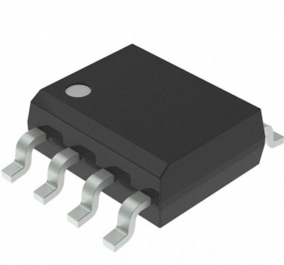
ATTINY 412
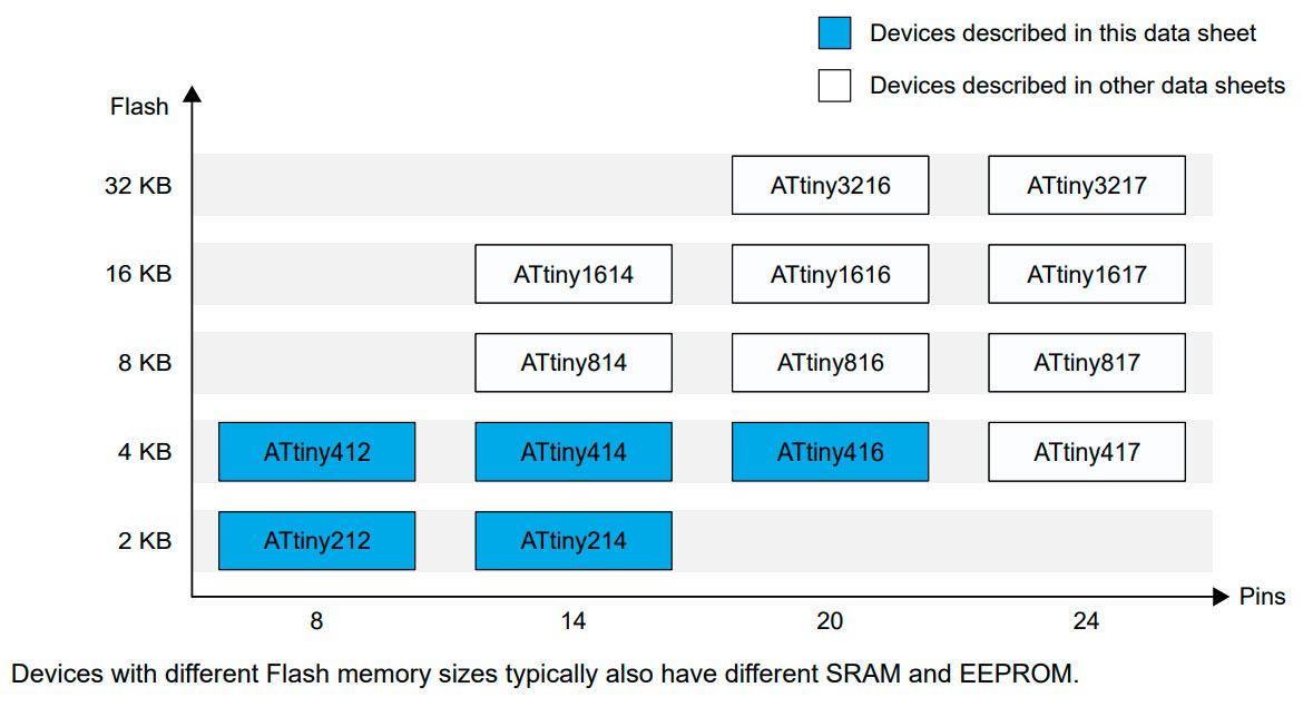
The ATtiny412 is a member of the tinyAVR®1-series of microcontrollers, using the AVR® processor with hardware multiplier, running at up to 20 MHz, with 2/4 KB Flash, 128/256 bytes of SRAM, and 64/128 bytes of EEPROM in a 8-, 14-, and 20-pin package.
Cost around: $0,50 in bulk
From FabAcademy chatgpt: What's about attiny 412?
ATtiny412: Key Features
- Architecture: 8-bit AVR, Harvard RISC
- Clock Speed: Up to 20 MHz
- Memory:
- Flash: 4 KB (for storing programs)
- SRAM: 256 bytes (for runtime data)
- EEPROM: 128 bytes (for storing non-volatile data)
- Power Consumption: Low-power operation, ideal for battery-based projects
- I/O Pins: 6 configurable GPIOs
- Peripherals:
- ADC (10-bit) for reading analog sensors
- Timers & Counters for precise timing operations
- PWM for motor control and LED dimming
- USART for serial communication
- Programming Interface: Uses UPDI (Unified Programming and Debugging Interface), meaning you only need a single pin to program it.
- Package: Available in 8-pin packages, making it compact and easy to integrate
To be able to use the ATtiny412 chip, we need to install the Arduino IDE and then install the MegaTinyCore. (video)
Types:
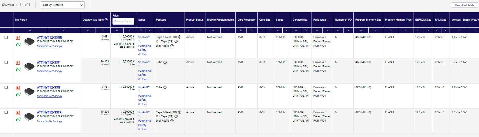
Attiny 412 Datasheet from digikey
Device |
AtTINY 412 |
|
Pins |
8 |
|
SRAM |
256 B |
|
|
Start Adress |
0x3F00 |
Flash |
4 KB |
|
|
Page size |
64 KB |
|
Number of Pages |
64 |
|
Start Adress |
0x8000 |
EEPROM |
128 B |
|
Max. frequency (Mhz) |
20 |
|
|
Page size |
32 B |
|
Number of pages |
4 |
|
Start Adress |
0x1400 |
16-bit Timer/Counter type A (TCA) |
1 |
|
16-bit Timer/Counter type B (TCB) |
1 |
|
12-bit Timer/Counter type B (TCB) |
1 |
|
Real-Time Counter (RTC) |
1 |
|
USART |
1 |
|
SPI |
1 |
|
TWI (I2C) |
1 |
|
ADC |
1 |
|
ADC channels |
1 |
|
DAC |
1 |
|
AC |
1 |
|
AC inputs |
1p/1n |
|
Peripheral Touch Controller (PTC) |
No |
|
Configurable Custom Logic |
1 |
|
Window Watchdog |
1 |
|
Event System channels |
6 |
|
General purpose I/O |
6 |
|
External interrupts |
6 |
|
CRCSCAN |
1 |
|
Pinout
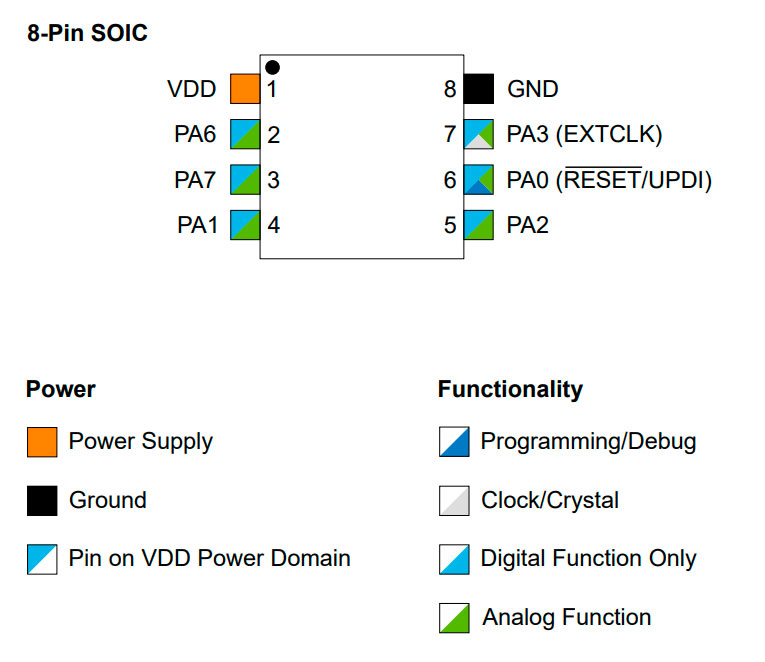
Table 5-2. PORT Function Multiplexing, Eight Pins
SOIC 8-Pin |
Pin Name (1,2) |
Other/ Special |
ADC0 |
AC0 |
DAC0 |
USART0 |
SPI0 |
TWI0 |
TCA0 |
TCB0 |
TCD0 |
CCL |
|
6 |
PA0 |
RESET/UPDI |
|
AIN0 |
|
|
XDIR |
SS |
|
|
|
|
LUT0-IN0 |
4 |
PA1 |
|
AIN1 |
|
|
TxD(3) |
MOSI |
SDA |
WO1 |
|
|
LUT0-IN1 |
|
5 |
PA2 |
EVOUT0 |
AIN2 |
|
|
RxD(3) |
MISO |
SCL |
WO2 |
|
|
LUT0-IN2 |
|
7 |
PA3 |
EXTCLK |
AIN3 |
OUT |
|
XCK |
SCK |
|
WO0/WO3 |
|
|
|
|
8 |
GND |
|
|
|
|
|
|
|
|
|
|
|
|
1 |
VDD |
|
|
|
|
|
|
|
|
|
|
|
|
2 |
PA6 |
|
AIN6 |
AINN0 |
OUT |
TxD |
MOSI(3) |
|
|
WO0 |
WOA |
LUT0-OUT |
|
3 |
PA7 |
|
AIN7 |
AINP0 |
|
RxD |
MISO(3) |
|
WO0(3) |
|
WOB |
LUT1-OUT |
|
Notes:
1. Pin names are of type Pxn, with x being the PORT instance (A, B) and n the pin number. Notation for signals isPORTx_PINn. All pins can be used as event inputs.
2. All pins can be used for external interrupts, where pins Px2 and Px6 of each port have full asynchronous detection.
3. Alternate pin positions. For selecting the alternate positions, refer to section 15. PORTMUX - Port Multiplexer.
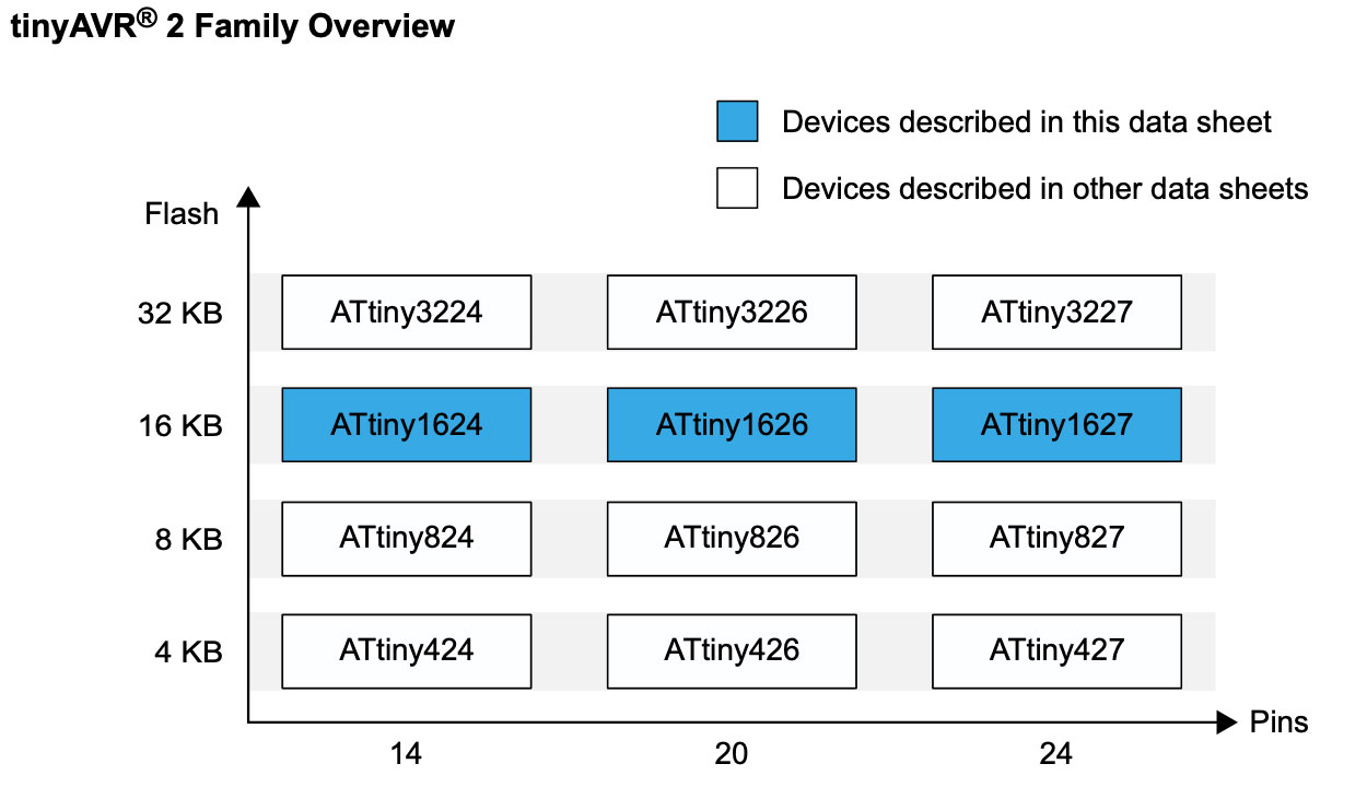
ATTINY 1624
The ATtiny1624 microcontroller of the tinyAVR® 2 family are using the AVR® CPU with hardware
multiplier, running at up to 20 MHz, with 16 KB Flash, 2 KB of SRAM, and 256B of EEPROM available in a 14-pin package.
Cost around: $0,80 in bulk
FabAcademy ChatGPT Key diferences with Attiny 412
Key Differences |
||
Feature |
ATtiny412 |
ATtiny1624 |
Architecture |
8-bit AVR |
8-bit AVR |
Flash Memory |
4 KB |
16 KB |
SRAM |
256 B |
2 KB |
EEPROM |
128 B |
256 B |
Clock Speed |
20 MHz |
20 MHz |
I/O Pins |
6 |
17 |
ADC (Analog Pins) |
10-bit |
12-bit |
PWM Channels |
2 |
3 |
USART (Serial Communication) |
1 |
2 |
I²C / SPI |
Yes |
Yes |
Programming Interface |
UPDI |
UPDI |
Power Consumption |
Very low |
Low but higher than 412 |
Package Options |
8-pin |
14, 20-pin |
Summary of Differences
- Memory: ATtiny1624 has 4x more Flash and 8x more SRAM, making it better for complex programs.
- I/O Pins: ATtiny1624 has 17 pins vs. 6 on ATtiny412, allowing for more peripherals.
- ADC & PWM: ATtiny1624 has better ADC resolution (12-bit vs. 10-bit) and more PWM channels.
- Serial Communication: ATtiny1624 has two USARTs vs. only one on ATtiny412, allowing for multiple serial connections.
- Size & Power Efficiency: ATtiny412 is smaller and more power-efficient, while ATtiny1624 offers more features.
Attiny 1624 Datasheet from digikey
Device |
ATtiny1624 |
Pins |
14 |
Package |
SOIC, TSSOP |
Maximum frequency (MHz) |
20 |
General purpose I/O |
12 |
PORT |
PA[7:0], PB[3:0] |
External interrupts |
12 |
Event system channels |
6 |
CCL LUTs |
4 |
Real-Time Counter (RTC) |
1 |
16-bit Timer/Counter type A (TCA) |
1 |
16-bit Timer/Counter type B (TCB) |
2 |
12-bit Timer/Counter type D (TCD) |
- |
USART/SPI master |
2 |
SPI |
1 |
TWI (I2C) |
1 |
ADC (channels) |
1 (9) |
DAC |
- |
Analog Comparators (inputs) |
1 (4p/3n) |
Peripheral Touch Controller (PTC) (self cap/mutual cap channels) |
- |
Unified Program and Debug Interface (UPDI) activated by shared pin using high-voltage signal or fuse override |
1 |
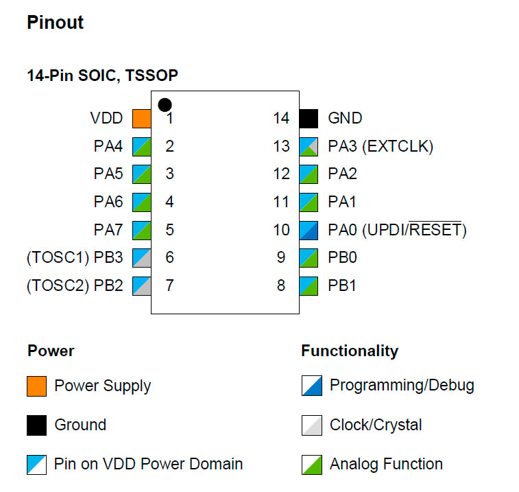
Pinout
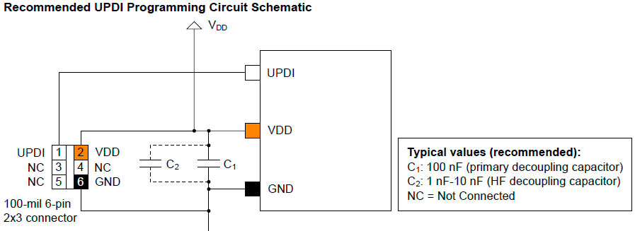
Conecction for UDP Programming
The standard connection for UPDI programming is a 100-mil 6-pin 2x3 header. Even though three pins are sufficient for programming most AVR devices, it is recommended to use a 2x3 header since most programming tools are delivered with 100-mil 6-pin 2x3 connectors.
The decoupling capacitor between VDD and GND must be placed as close to the pin pair as possible. The decoupling capacitor must be included even if the UPDI connector is not included in the circuit.
The following figure shows the recommendation for connecting a UPDI connector to the device.
XIAO ESP32C6
This Microcontroller features two processors, one high-performance and one low-power, thus being capable of performing rapid computations as well as staying in low-consumption state for saving battery. It has allocated 512KB of SRAM and 4MB of flash allowing thus for large space for programming. It uses the Matter connectivity protocol, thus allowing for open connectivity with low-energy Bluetooth, WiFi, Threat and Ethernet devices. More specifically it supports 2.4 GHz WiFi 6, Bluetooth® 5.3, Zigbee, and Thread (802.15.4). Below the specs of this microcontroller.
Table 1 Specs of XIAO ESP32C6. Source Seedstudio, https://wiki.seeedstudio.com/xiao_esp32c6_getting_started/
Microcontroller |
XIAO ESP32C6 |
|
Processor |
Espressif ESP32-C6 SoC |
|
Two 32-bit RISC-V processors, with the high-performance one running up to 160 MHz, and the low-power one clocking up to 20 MHz |
||
Wireless |
Complete 2.4GHz Wi-Fi 6 subsystem |
|
BLE: Bluetooth 5.0, Bluetooth Mesh |
||
Zigbee,Thread,IEEE 802.15.4 |
||
On-chip Memory |
512KB SRAM & 4MB Flash |
|
Interface |
1x UART,1x LP_UART, 1x IIC, 1x LP_IIC, 1x SPI,11x GPIO(PWM), 7x ADC, 1xSDIO |
|
1x Reset button, 1x Boot button |
||
Dimensions |
21 x 17.8 mm |
|
Power |
Input voltage |
Type-C: 5V |
Circuit operating Voltage (ready to operate) |
USB:5V@9mA |
|
Charging battery current |
100mA ~ 30 mA ~ 2.5 mA ~ 15 μA |
|
Power Consumption Model(Supply Power: 3.8V) |
Modem-sleep Model |
|
Light-sleep Model |
||
Deep Sleep Model |
||
Working Temperature |
-40°C ~ 85°C |
|
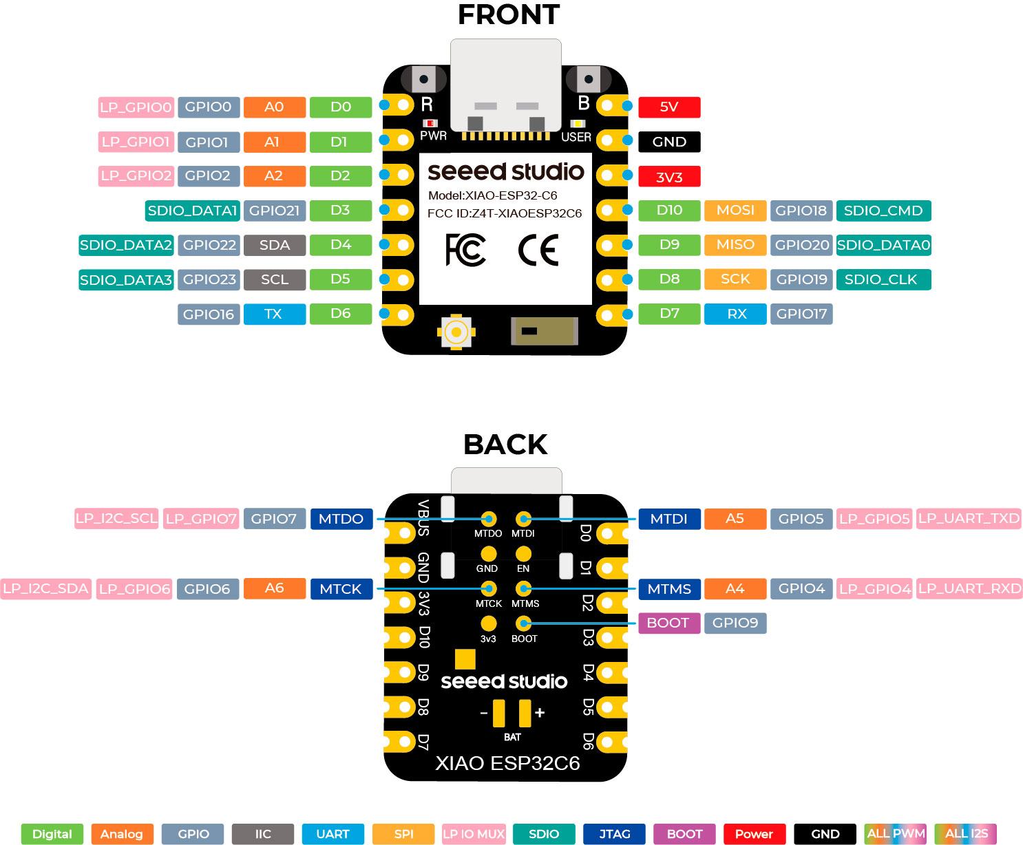
Regarding the Pinout, it has 3 analogic and 11 digital connections. Also it has IIC and SPI buses, plus two UART ports for data monitoring, see an illustration of the pinout scheme below (source https://wiki.seeedstudio.com/xiao_esp32c6_getting_started/)
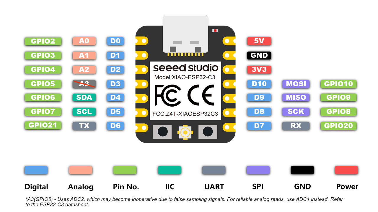
Xiao ESP32 C3
The XIAO ESP32C3 is a microcontroller similar to the ESP32C6 but with more limited features. For instance, it only has a single core of similar performance to the one of the C6, it has less SRAM (400KB) and connectivity (compatibility with WiFi 6 is not assured and it has not Zigbee and Thread connectivity). Also it has less number of interfaces. Below it is shown the full specs of the microcontroller (Source Seedstudio).
Table 2 Specs of the XIAO ESP32C3 Source Seedstudio https://wiki.seeedstudio.com/XIAO_ESP32C3_Getting_Started/
Microcontroller |
XIAO ESP32C3 |
|
Processor |
Espressif ESP32-C3 SoC |
|
RISC-V single-core 32-bit chip processor with a four-stage pipeline that operates at up to 160 MHz |
||
Wireless |
Complete 2.4GHz Wi-Fi subsystem |
|
BLE: Bluetooth 5.0, Bluetooth Mesh |
||
On-chip Memory |
400KB SRAM & 4MB Flash |
|
Interface |
1x UART, 1x IIC, 1x SPI,11x GPIO(PWM), 4x ADC |
|
1x Reset button, 1x Boot button |
||
Dimensions |
21 x 17.8 mm |
|
Power |
Input voltage |
Type-C: 5V |
Circuit operating Voltage (ready to operate) |
USB:5V@9mA |
|
Charging battery current |
350mA ~ 24 mA ~ 3 mA ~ 44 μA |
|
Power Consumption Model(Supply Power: 3.8V) |
Modem-sleep Model |
|
Light-sleep Model |
||
Deep Sleep Model |
||
Working Temperature |
-40°C ~ 85°C |
|
Regarding the pinout, the C3 it has similar interfaces to the C6, but with less connections. For instance it does not have LD IO nor SDIO connections. Still it has the same number of analog ports, digital ports, SDA and UART connections, SPI buses, ground and energy connections (5V or 3V3). Se a schematic of the pinout below (Source Seedstudio):
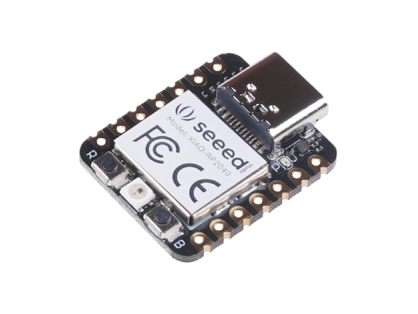
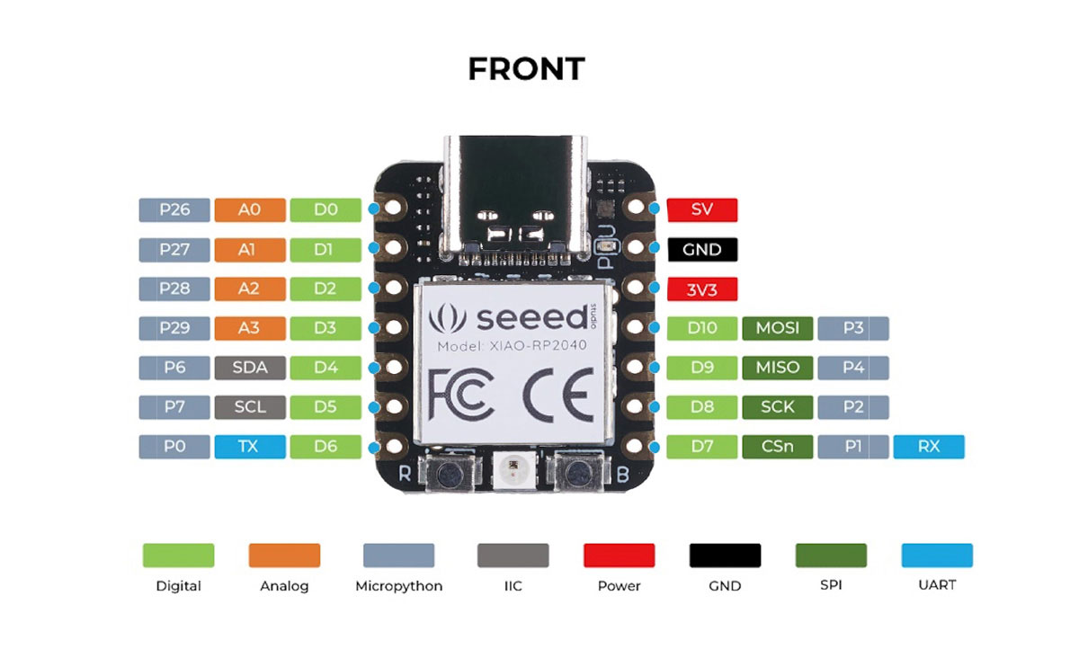
XIAO RP2040
Characterisitics to keep in mind:
- Powerful MCU
- Rich on-chip resources
- Flexible compatibility: Support Micropython/Arduino/CircuitPython
- Easy project operation: Breadboard-friendly & SMD design, no components on the back
- Small size
- Multiple interfaces: 11 digital pins, 4 analog pins, 11 PWM Pins,1 I2C interface, 1 UART interface, 1 SPI interface, 1 SWD Bonding pad interface.
Table with specifications:
XIAO RP2040 |
|
Processor |
Dual ARM Cortex-M0 + processor up to 133 MHz |
Flash Memory |
2MB |
SRAM |
264KB |
Digital I/O Pins |
11 |
Analog I/O Pins |
4 |
PWM Pins |
11 |
I2C interface |
1 |
SPI interface |
1 |
UART interface |
1 |
Power suooky and downloading interface |
Type-C |
Power |
3.3V/5V DC |
Dimesnions |
21 x 17.8 x 3.5 mm |
Site |
https://wiki.seeedstudio.com/XIAO-RP2040/ |
Key question for FabGPT: For which type of project is it recommended to use the microcontroller xiao rp2040?
The XIAO RP2040 is well-suited for projects that require fast processing, real-time control, and custom peripherals, thanks to its RP2040 microcontroller from Raspberry Pi. According to the class transcript, the RP2040 is notable for:
- High-Speed Performance: Runs at 133 MHz by default but can be overclocked up to 250 MHz, making it ideal for real-time applications.
- Programmable I/O (PIO): Includes additional customizable processors that allow you to design your own peripherals, which is great for advanced signal processing or custom communication protocols.
- Compact Size: The XIAO RP2040 is tiny, making it great for wearable tech, embedded systems, and space-constrained applications.
- Good Peripheral Support: Comes with multiple GPIOs, SPI, I2C, UART, and PWM, making it versatile for sensor-based projects or robotics.
- Lower Power Consumption: While not as low as dedicated low-power microcontrollers, it is still efficient for battery-powered devices.
Recommended Projects for XIAO RP2040
- Wearable Electronics (small size, good processing power)
- Portable Data Loggers (fast processing, real-time capabilities)
- Real-time Signal Processing (audio synthesis, LED animations)
- Custom Communication Interfaces (thanks to PIO)
- DIY Robotics and Automation (high-speed control loops)
- IoT Prototypes (though it lacks built-in WiFi, it can connect via external modules)
Would you like guidance on how to program it or integrate it into your final project?
Datasheet
https://files.seeedstudio.com/wiki/XIAO-RP2040/res/rp2040_datasheet.pdf
Programming ATtiny412
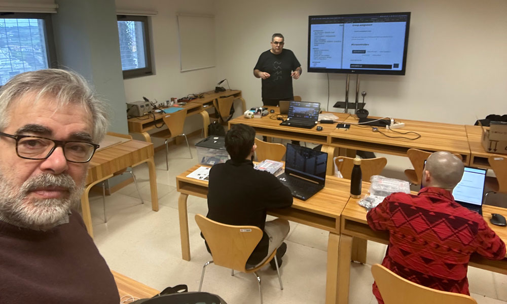
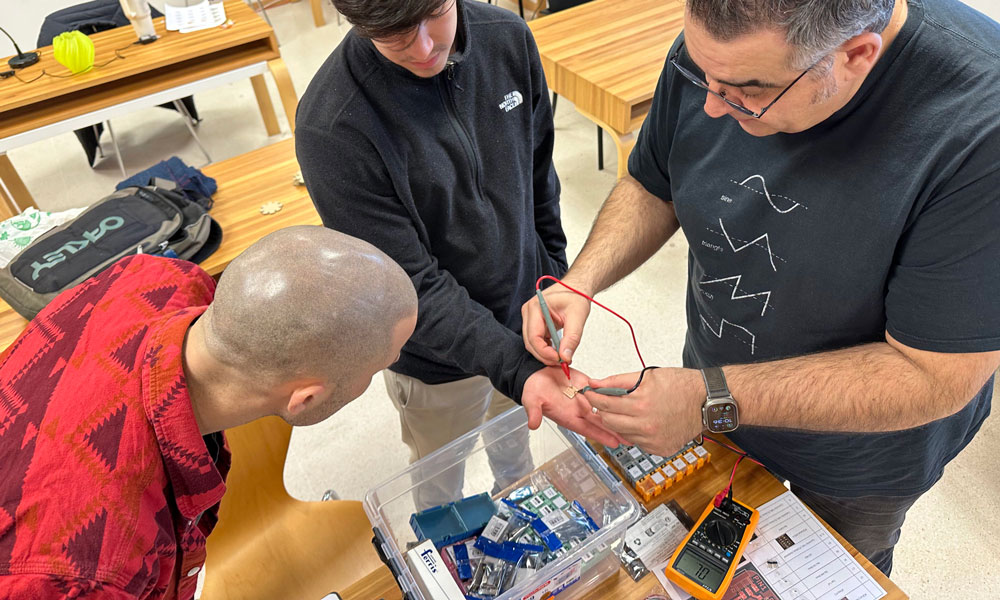
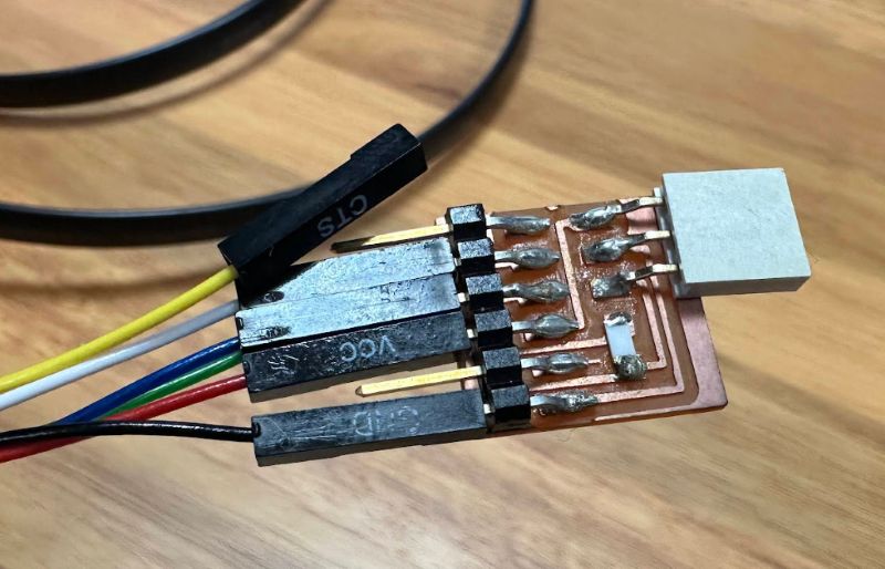
For the group assignment, We were in charge of reviewing and documenting the ATtiny412 microprocessor. On Thursday, February 14th, Luis provided us with the materials to build a Serial UPDI-3 pin, and with his help, We were able to get a functional programmer working.

We consulted the information about this electronic board here:
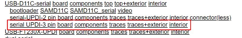
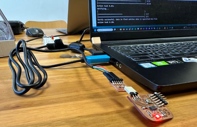
Using this programmer, We uploaded a simple program to the Hello World Luis Díaz-Faes board. This board was designed by Luis during Week 6 of his FabAcademy training in 2022 and features a Megatiny412.
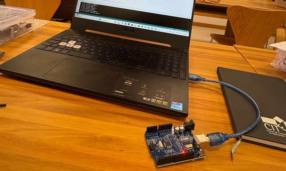
Up until now, We had been uploading code to an Arduino Uno via USB. To send it to the development board through the programmer, We needed to select the correct settings in the Arduino IDE.
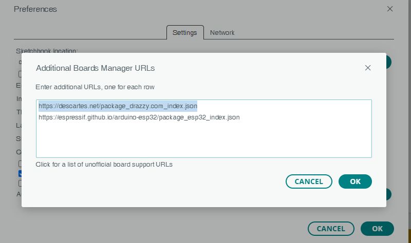
First, We selected: File > Preferences > Aditional boards manager > Add URL:
https://drazzy.com/packkage_drazzy.com_index.json
and then double-clicked but this URL did not work.

After checking the web for alternative URLs We found this reference
https://descartes.net/package_drazzy.com_index.json
We then copied & pasted this URL and We were able to install it.
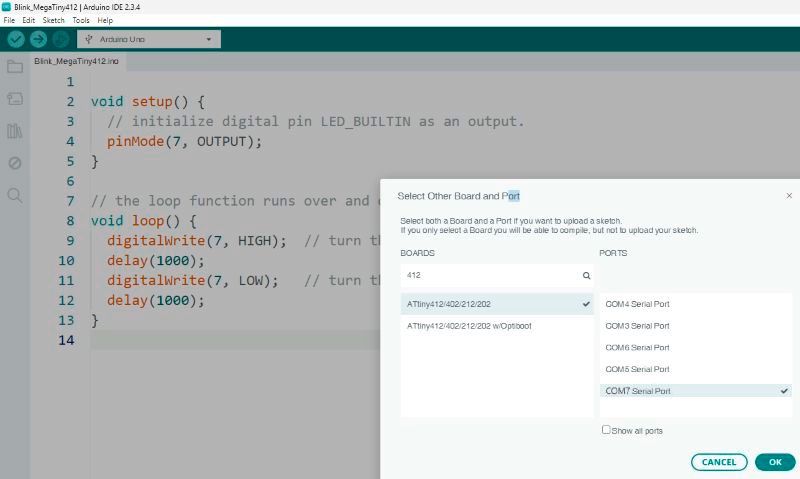
Later, We selected the ATtiny412 board and the PORT and clicked OK.
Then, under Tools > Programmer, We chose serialUPDI - SLOW: 57000 baud .
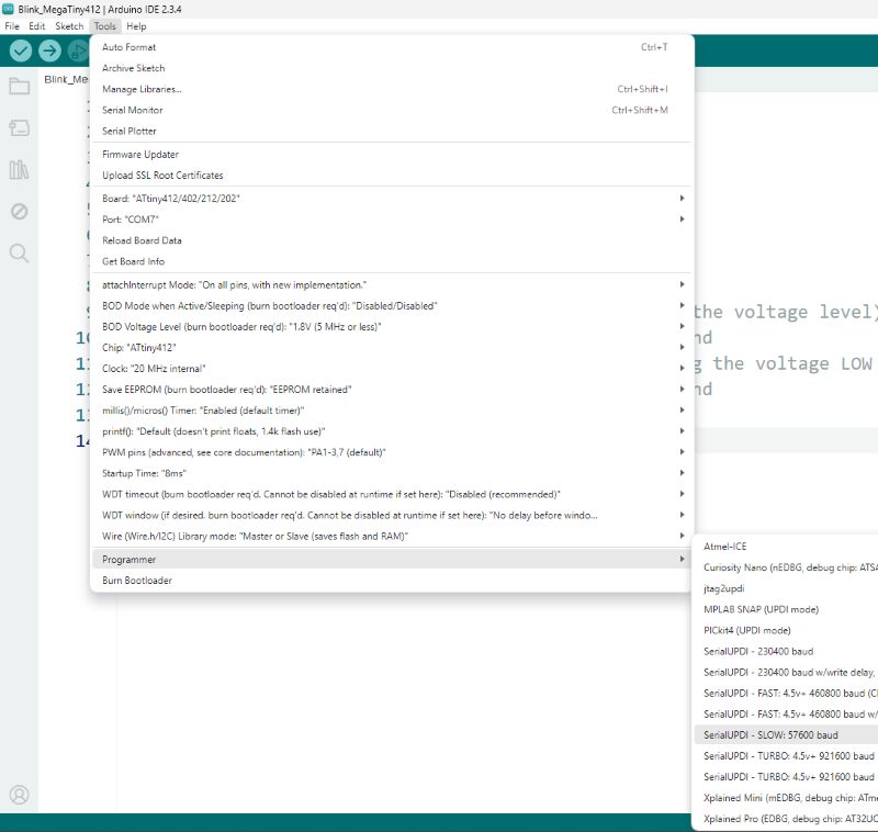
After picking the right programmer, We uploaded
using
Programmer
, and as you can see in the video, the programming went smoothly.
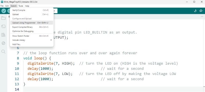
Blink_Megatiny412
                        void setup() {

  // initialize digital pin LED_BUILTIN as an output.

  pinMode(7, OUTPUT);

}


// the loop function runs over and over again forever

void loop() {

  digitalWrite(7, HIGH);  // turn the LED on (HIGH is the voltage level)

  delay(1000);                      // wait for a second

  digitalWrite(7, LOW);   // turn the LED off by making the voltage LOW

  delay(1000);                      // wait for a second

}