Week 05
3D scanning and printing
Group assignment
- test the design rules for your 3D printer(s)
Prusa i3 MK3S & MK3S+
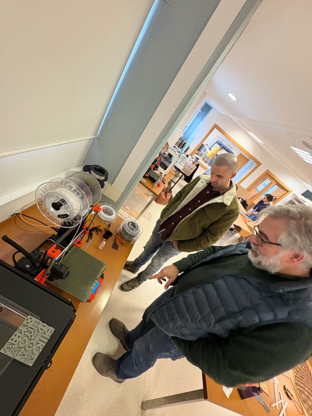
In this group assignment, we tested our 3D printer by printing a standard model designed to evaluate the design rules and manufacturing limits of the machine. For this test, we used the 3D printers available at Fablab ETSAC, which include two Prusa i3 MK3S & MK3S+. These printers have the following characteristics:
- Build volume: 25 x 21 x 21 cm
- Layer height: 0.05 – 0.35 mm
- Max travel speed: 200+ mm/s
- Max hotend/heatbed temp.: 300 °C / 120 °C (572 °F / 248 °F)
- Supports only a 1.75 mm filament.
Key advantages include a filament sensor, power failure recovery, automatic bed leveling, which was a massive upgrade for the etsac laboratory compared to the printers they had before (SuperPINDA on MK3S+), and a quiet operation thanks to Trinamic 2130 stepper drivers. The Einsy RAMBo 32-bit control board enhances motor accuracy and reduces vibrations. Additionally, they support a wide range of materials (PLA, PETG, ABS, TPU, composites, etc.).
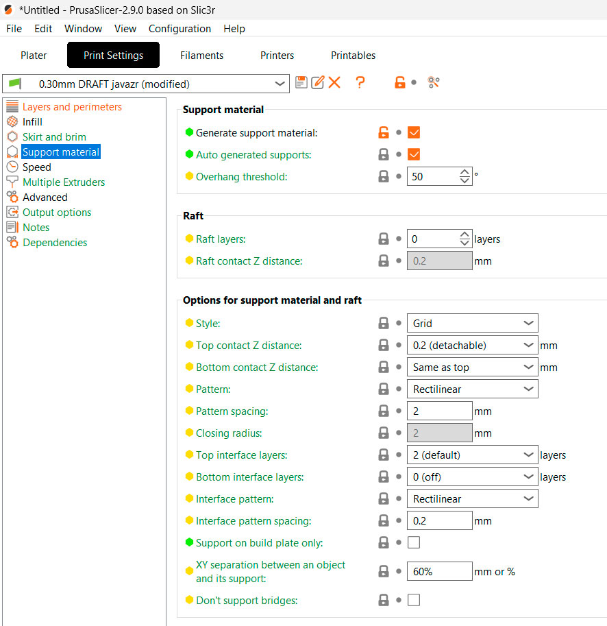
To conduct the test, we used PLA filament and a 0.4 mm nozzle. Additionally, the rest of the printing parameters can be found in the following images:
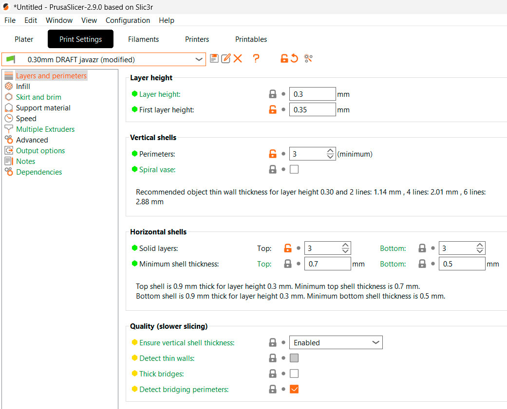 n>
n>


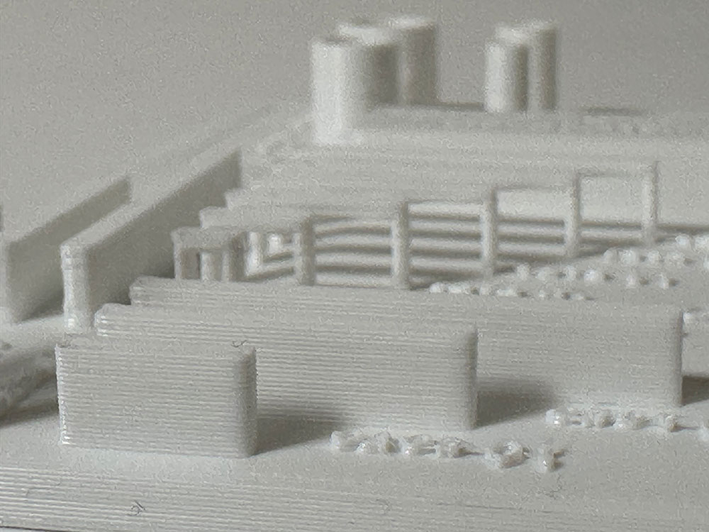
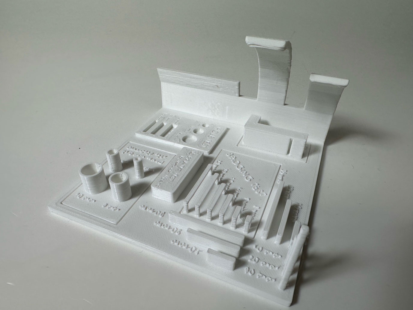
To characterize the machine, we conducted the following tests, sourced from Thingiverse.com.
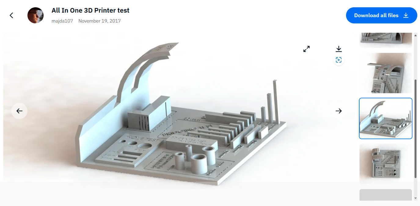
Link: https://www.thingiverse.com/thing:2656594
By this test we wanted to evaluate the next parameters.
· scale test
· overhang test
· hole test
· diameter test
· bridging test
Here is the result:
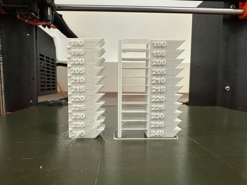
Temperature test:
For the temperature test, we first downloaded the .stl file.
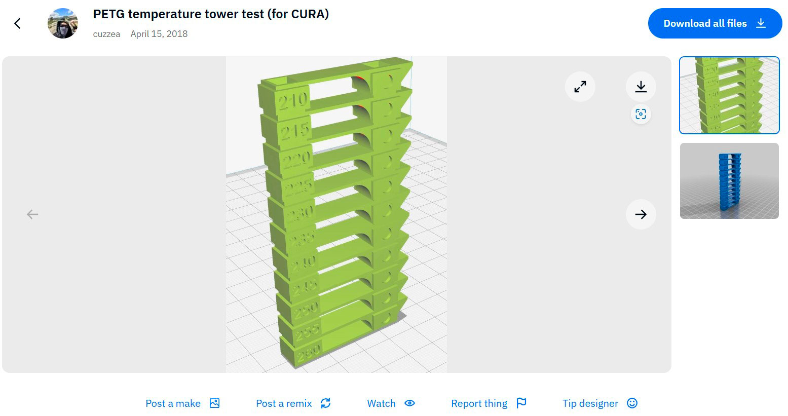
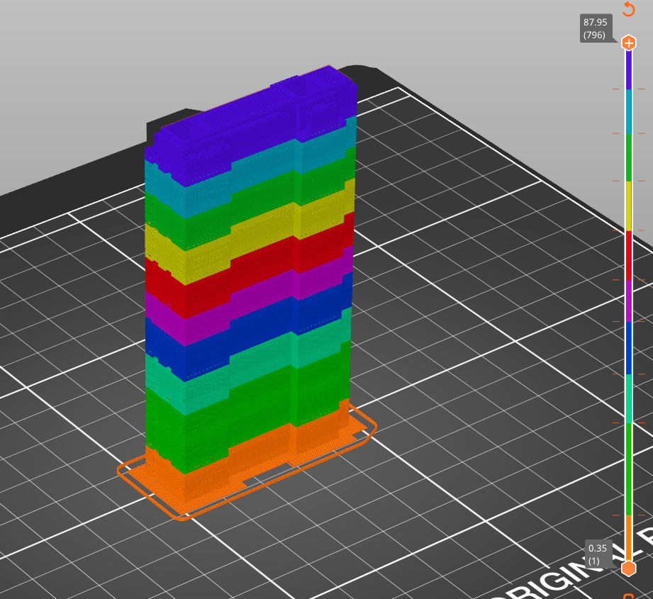
Then, we divided the model into layers.
Then, you need to select the option in the first field to enter a G-code command manually. In the second option, input the G-code as follows:
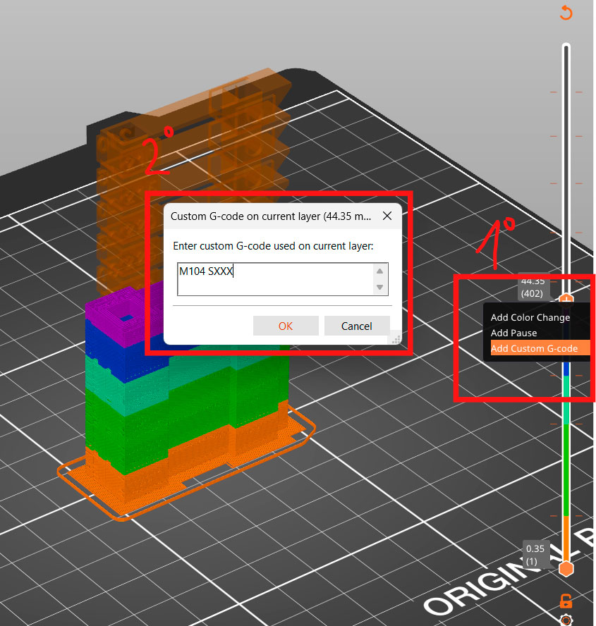
M104 SXXX ; Set hotend temperature
M140 SXXX ; Set bed temperature (optional)
Note: Use M109 SXXX instead of M104 if you want the printer to wait until the new temperature is reached before continuing the print
Here is the result:
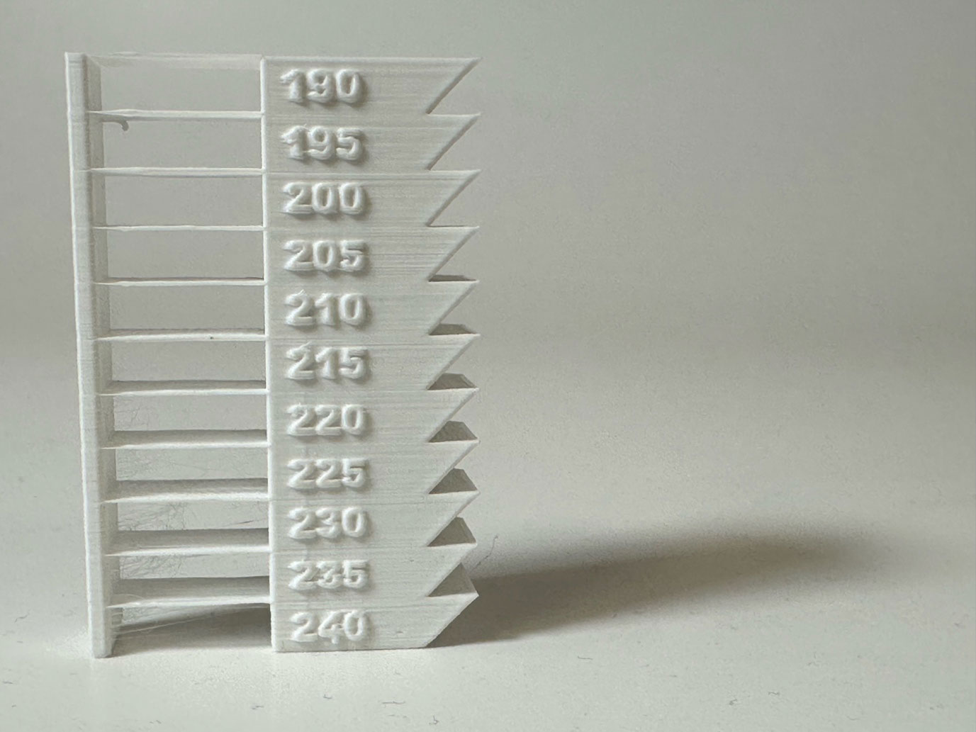
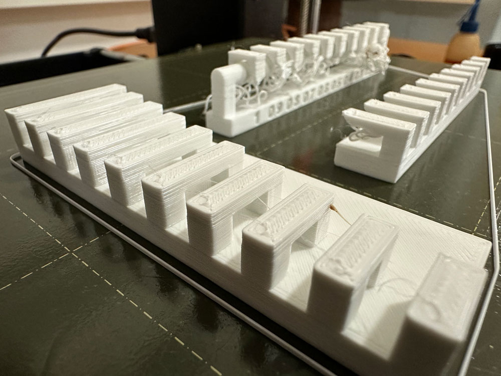
Afterwards, we conducted the tests we obtained from Neil's page, which are much more straightforward since you only need to download the .stl file and print it.
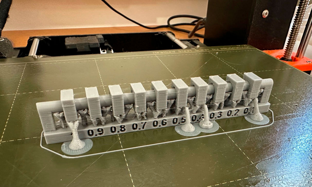
However, we encountered an issue because we printed three tests simultaneously, and one of them required supports. As you can see in the following image, this resulted in a failure, so we decided to repeat the test.
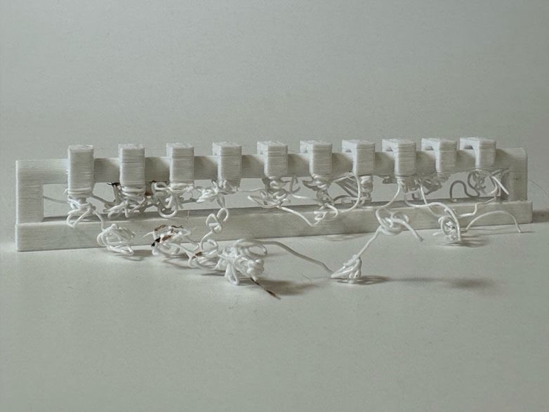
It can be seen that in this test, the filament deatil was extruded poorly, and we believe this was due to the layer height being too high, if you want more detail you should use a 0.2 mm layer height. Additionally, the model required supports, which we didn’t enable in PrusaSlicer.
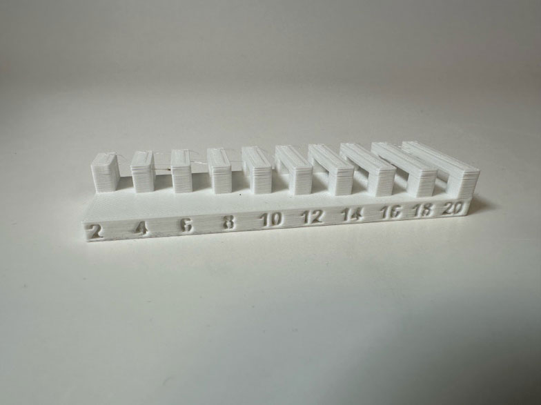
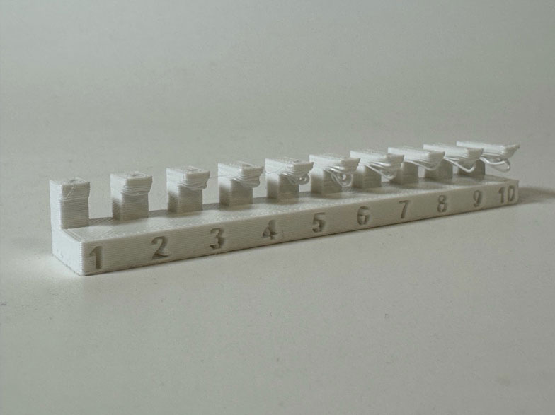
Here are the results of the other two tests. In the first test (bridging), it is evident that we used a lot of material for the layers, as the filament barely fell. On the other hand, the overhang test yielded a poorer result, with the filament drooping significantly, starting with the second shortest measurement.
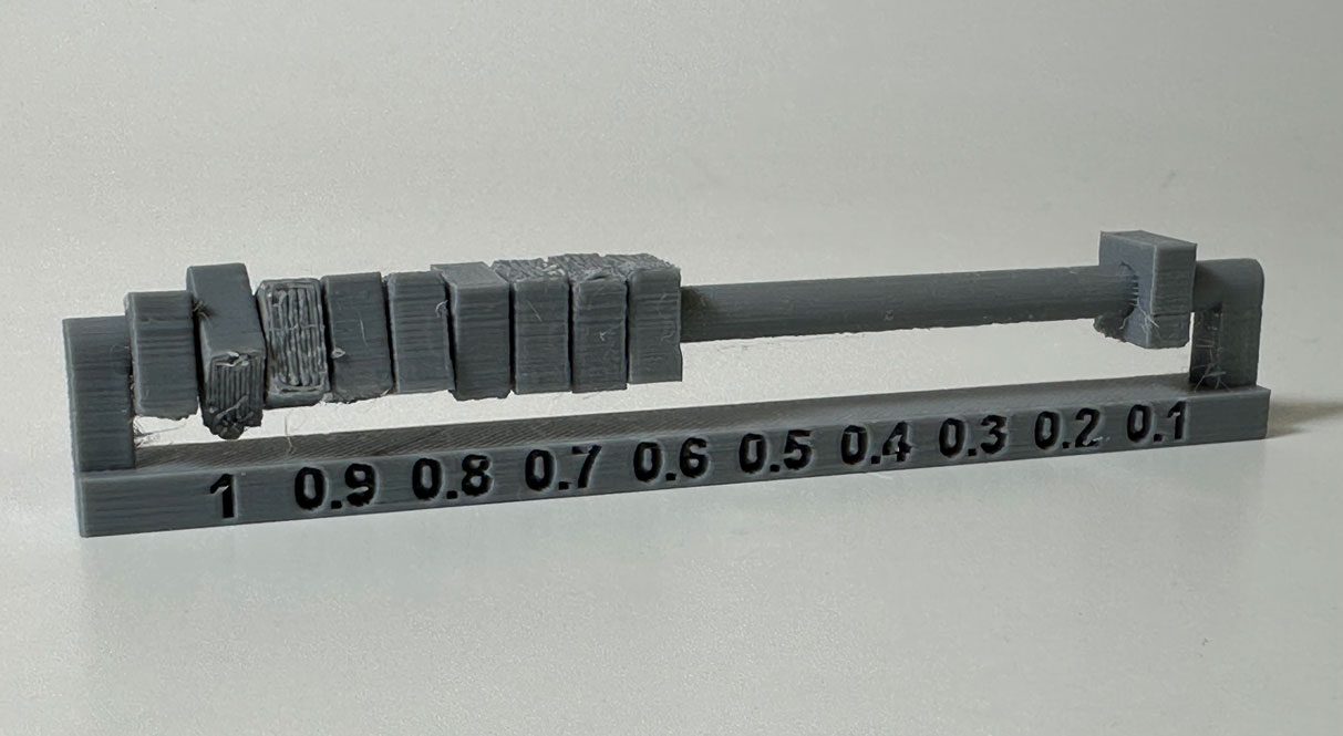
Finally, we repeated the clereance test
It showed that the 0.2 was the best option.
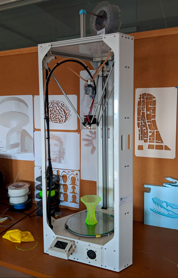
DELTA KOSSEL ETSAC
Our delta 3D printer holds the extruder using three arms that can move independently along the Z-axis. The base points of the arms form a triangle, just like the points where each arm connects to the extruder.
To feed the filament, it uses a Bowden system, where the extruder is placed away from the print head. In our case, it’s suspended using three elastic bands. The extruder has three fans to help control the layer temperature.
The printer has a heated bed with a fixed glass plate that stays in place during printing.
Our printer is based on a RepRap design, and most of its parts were printed using another 3D printer. Its aluminum frame provides the rigidity needed to ensure stability and precision when depositing the melted filament exactly where it needs to go. Like other 3D printers, the nozzle diameter can be swapped out. Right now, we have a 0.8 mm nozzle installed.
Technical Specifications: Maximunm: 580 mm Bed Diameter: 300 mm Nozzle type: E3D V6 Nozzle Diameter: 0.8 mm (interchangeable) Heated Bed: Yes Filament Diameter: 1.75 mm Supported Materials: ABS, PLA, PETG Melting Temperature: <260°C Firmware: Marlin Board: Arduino Mega |
Advantages & Disadvantages:
One of the main advantages of delta printers is their speed and print quality. They also allow for taller prints—over 500 mm in height. However, their maximum print area is limited to a circular 300 mm diameter.
A downside of our specific model is the complexity of calibration when changing the nozzle. On our Prusa printers, this process is automatic thanks to the PINDA sensor, but on the Delta, a pressure sensor is required. Even though our printer was already calibrated, I decided to go through the process from scratch to document the entire procedure.
Self-calibration and leveling of our Delta Kossel Plus
The information I will collect here follows this calibration guide by Adrian Castillo. Autocalibrado y UBL (1.1.6) | Yakandu3D
What do I need and what do I need to know?
· Install Pronterface to connect and send commands to the printer
· Check that the glass is correctly fixed to the printer bed.
Each of the three grippers should be positioned as close to the edge of the bed as possible.
· A pressure sensor such as the XCR3D for E3D V6 Nozzle.
· Connecting the sensor:
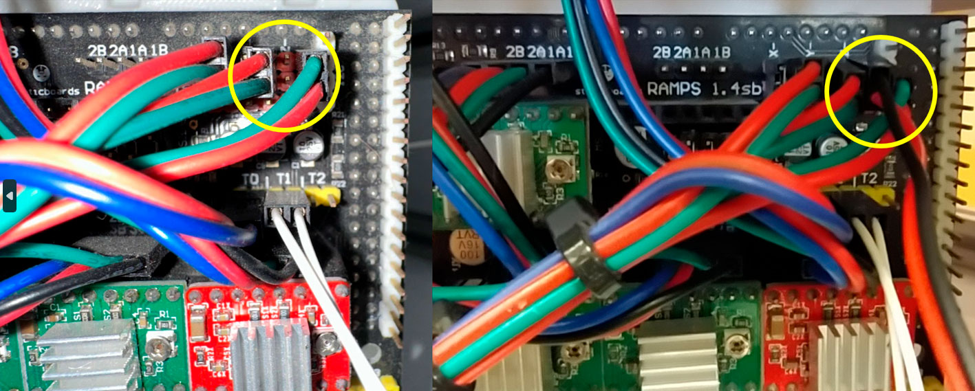
o I need to open the front cover of the printer to access the RAMPS 1.4 board, no screws need to be removed, I just need to pry it outwards to remove the cover with the fan. The connections on the board are already accessible
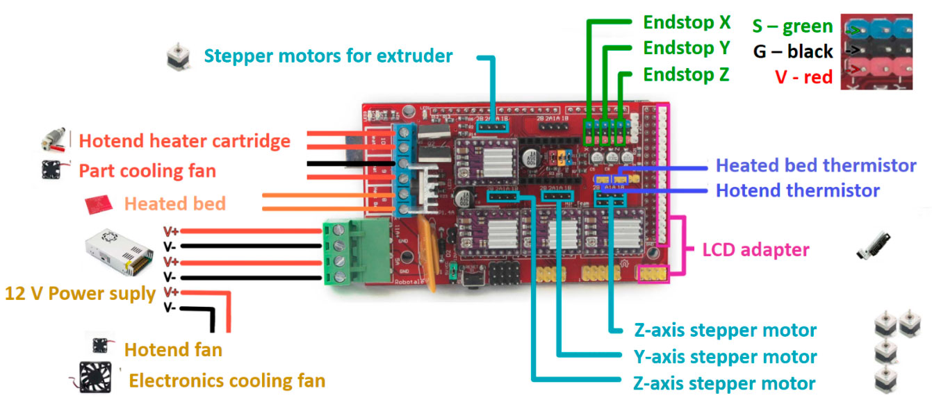
- Then I have to connect the Dupont connector of the pressure sensor to the free Z-terminal of the limit switch as shown in the picture.
Step-by-step procedure
1. Plug-in the printer using a USB cable (see image Proterface-01).
Select the port and set the baud rate to 250000, then click
"Connect."
A list of the printer's current settings will appear in the right-hand column.
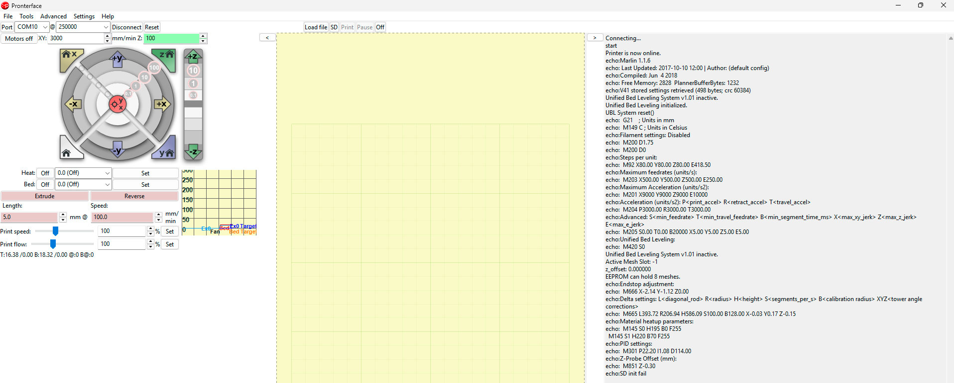
Pronterface - Delta ETSAC Connecting... start Printer is now online. echo:Marlin 1.1.6 echo: Last Updated: 2017-10-10 12:00 | Author: (default config) echo:Compiled: Jun 4 2018 echo: Free Memory: 2828 PlannerBufferBytes: 1232 echo:V41 stored settings retrieved (498 bytes; crc 60384) Unified Bed Leveling System v1.01 inactive. Unified Bed Leveling initialized. UBL System reset() echo: G21 ; Units in mm echo: M149 C ; Units in Celsius echo:Filament settings: Disabled echo: M200 D1.75 echo: M200 D0 echo:Steps per unit: echo: M92 X80.00 Y80.00 Z80.00 E418.50 echo:Maximum feedrates (units/s): echo: M203 X500.00 Y500.00 Z500.00 E250.00 echo:Maximum Acceleration (units/s2): echo: M201 X9000 Y9000 Z9000 E10000 echo:Acceleration (units/s2): P<print_accel> R<retract_accel> T<travel_accel> echo: M204 P3000.00 R3000.00 T3000.00 echo:Advanced: S<min_feedrate> T<min_travel_feedrate> B<min_segment_time_ms> X<max_xy_jerk> Z<max_z_jerk> E<max_e_jerk> echo: M205 S0.00 T0.00 B20000 X5.00 Y5.00 Z5.00 E5.00 echo:Unified Bed Leveling: echo: M420 S0 Unified Bed Leveling System v1.01 inactive. Active Mesh Slot: -1 z_offset: 0.000000 EEPROM can hold 8 meshes. echo:Endstop adjustment: echo: M666 X-2.14 Y-1.12 Z0.00 echo:Delta settings: L<diagonal_rod> R<radius> H<height> S<segments_per_s> B<calibration radius> XYZ<tower angle corrections> echo: M665 L393.72 R206.94 H586.09 S100.00 B128.00 X-0.03 Y0.17 Z-0.15 echo:Material heatup parameters: echo: M145 S0 H195 B0 F255 M145 S1 H220 B70 F255 echo:PID settings: echo: M301 P22.20 I1.08 D114.00 echo:Z-Probe Offset (mm): echo: M851 Z-0.30 echo:SD init fail |
2. Check connection to the printer: send command G28 (Autohome)
During the first calibration, it is recommended to restore the factory settings, clearing the EEPROM of any previous modifications.
- Send command: M502
loads the default factory settings stored in the firmware but does not save them to memory. - Send command: M500
Saves the current settings to the printer's EEPROM (permanent memory). - Send command: M501
Loads the previously saved settings from the EEPROM into the printer's active memory.
>>> M502 SENDING:M502 Echo:Hardcoded Default Settings Loaded Loaded >>> M500 SENDING:M500 echo:Settings Stored (498 bytes; crc 60651) >>> M501 SENDING:M501 echo:V41 stored settings retrieved (498 bytes; crc 60651) … |
3. I start the auto-calibration, which measures the printer's height, concavity, and other parameters. To do this, I send the following commands:
- G29 D // Disable the mesh leveling.
- M851 Z0 // Reset the Z-offset to 0.
- G33 P7 // Run auto-calibration. Multiple iterations may be needed.
- M500 // Save the calibration settings.
- M501 // Load the saved settings.
>>> G29 D SENDING: G29 D Unified Bed Leveling System v1.01 inactive >>>M851 Z0 Echo:Offset Z 0.00 >>> G33 P7 SENDING:G33 P7 G33 Auto Calibrate Checking... AC .Height:586.72 Ex:-1.50 Ey:-0.94 Ez:+0.00 Radius:204.46 .Tower angle : Tx:+0.02 Ty:+0.06 Tz:-0.08 Iteration : 01 std dev:0.945 .Height:587.90 Ex:-1.38 Ey:-2.03 Ez:+0.00 Radius:210.16 .Tower angle : Tx:+0.03 Ty:+0.07 Tz:-0.10 Calibration OK rolling back. .Height:586.72 Ex:-1.50 Ey:-0.94 Ez:+0.00 Radius:204.46 .Tower angle : Tx:+0.02 Ty:+0.06 Tz:-0.08 Save with M500 and/or copy to Configuration.h |
4. Detection of imperfections on the bed surfaceThis step is optional, unless the printing surface has been changed, or inconsistencies are detected in the execution of the first printing layer, in which case it is recommended to do so.G28 //Home all axes.
- G29 P1 //Generate a new bed mesh.
- G29 S //Save the mesh.
- G29 F10 //Enable mesh fade-out up to 10mm.
- G29 A //Activate the mesh.
- M500 //Save the settings.
- M501 //Load the saved settings.
This process ensures the bed leveling mesh is correctly set and applied during printing.
5. Finally, I need to set the Z-offset, which eliminates the height difference between the sensor's zero position and the actual position of the nozzle's tip.
To do this, I'll use the G1 Z(height) command. For example, sending G1 Z0 will position the printhead at the height where the probe would touch the glass surface. It's best to approach in small increments to avoid crashing the nozzle into the bed.
Before sending the G1 code, I must send a G28 to make an Autohome.
The best way to determine the correct offset is by placing a sheet of paper between the bed and the nozzle. When the nozzle barely touches the paper, the offset is correct. In my case, the correct offset was Z-0.4.G1 Z100
SENDING:G28 >>> G1 Z100 SENDING:G1 Z100 >>> G1 Z50 SENDING:G1 Z50 >>> G1 Z10 SENDING:G1 Z10 >>> G1 Z5 SENDING:G1 Z5 >>> G1 Z2 SENDING:G1 Z2 >>> G1 Z1 SENDING:G1 Z1 >>> G1 Z0 SENDING:G1 Z0 >>> G1 Z-0.1 SENDING:G1 Z-0.1 >>> G1 Z-0.2 SENDING:G1 Z-0.2 >>> G1 Z-0.3 SENDING:G1 Z-0.3 >>> G1 Z-0.4 SENDING:G1 Z-0.4 >>> G1 Z-0.5 SENDING:G1 Z-0.5 >>> G1 Z-0.4 SENDING:G1 Z-0.4 >>> G1 Z-0.5 SENDING:G1 Z-0.5 >>> M851 Z-0.5 SENDING:M851 Z-0.5 echo:Desfase Z -0.50 >>> M500 SENDING:M500 echo:Settings Stored (498 bytes; crc 36523) Mesh saved in slot 0 >>> M501 SENDING:M501 echo:V41 stored settings retrieved (498 bytes; crc 36523) Unified Bed Leveling System v1.01 active. |
6. Use the following command to enter the offset you just calculated:
- M851 Z-0.5 // Newly calculated offset
- // Save the settings
- M501 // Load the saved settings
That's it! Now I have the auto-calibration and Z-offset set and loaded, so I'm ready to print. However, it's a good idea to check that running G1 Z0 positions the nozzle correctly against the bed. I'll be careful not to crash the nozzle into the bed!
Now I can start printing the test files. However, when I ran the temperature test, I noticed that the offset I set is too tight, and the nozzle is too close to the bed. This caused a clog in the extruder, which I need to fix before moving forward.
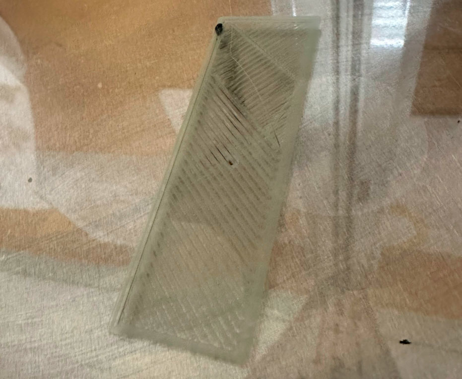
I have adjusted the offset again with the steps indicated in 5 and 6 Z= -0.1
Everything in order
