Week 03
Computer-controlled cutting
Group assignment
- Do your lab's safety training
- Characterize your lasercutter's focus, power, speed, rate, kerf, joint clearance and types.
- Document your work to the group work page and reflect on your individual page what you learned.
LASER CUTTER MACHINE
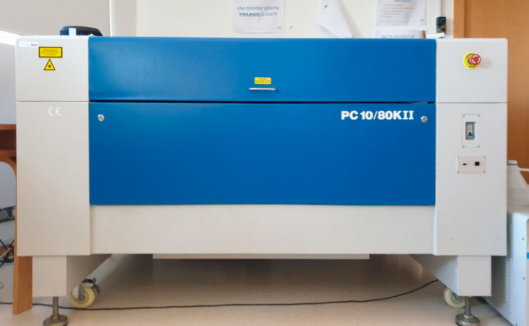
The laser cutter that we have at the ETSAC is the PC 10/80KII. Which has the following technical specifications:
Laser |
CO2 10600 nm |
Laser power |
80 and 130 W / 50W RF |
Work area |
1000x800 mm |
Dimensions |
1600 x 1300 x 1100 mm |
Cutting width |
0 to 20 mm (depends on the material) |
Engraving velocity |
0 to 30.000 mm/min |
Cutting velocity |
0 to 30.000 mm/min |
Resolution |
< 4000 dpi |
Power consumption |
1250W |
Interface |
USB (PC) / USC for pendrive |
Control |
Advance system of DSP control |
Refrigeration |
Water |
Air assistant |
Standard in the laser head |
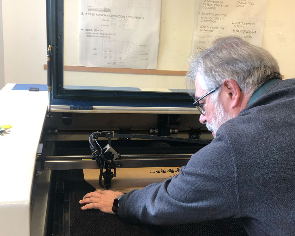
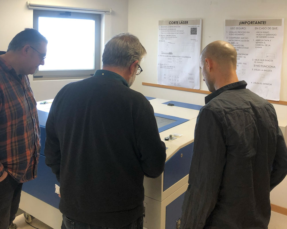
For this machine, within the group of fab students, there was a significant difference in experience levels. On one hand, Pepe had extensive experience using the machine for many years. On the other hand, Francisco and Pablo were using the machine for the first time. Because of this, Pepe took the lead, and with the help of Luis (the instructor), they both explained the process and the precautions needed to ensure the machine could perform a good piece of work.

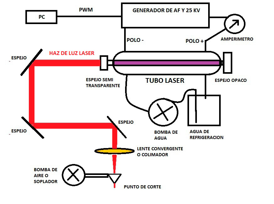
First, we understood how the machine works, and it can be explained with the following schema:
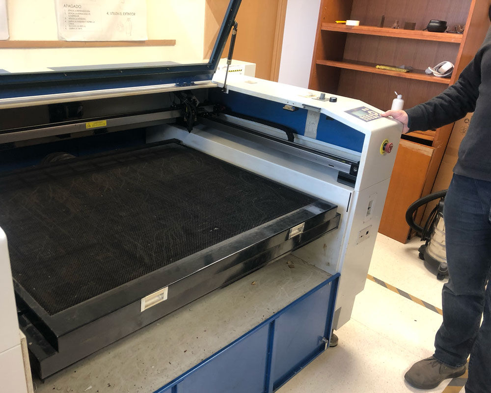
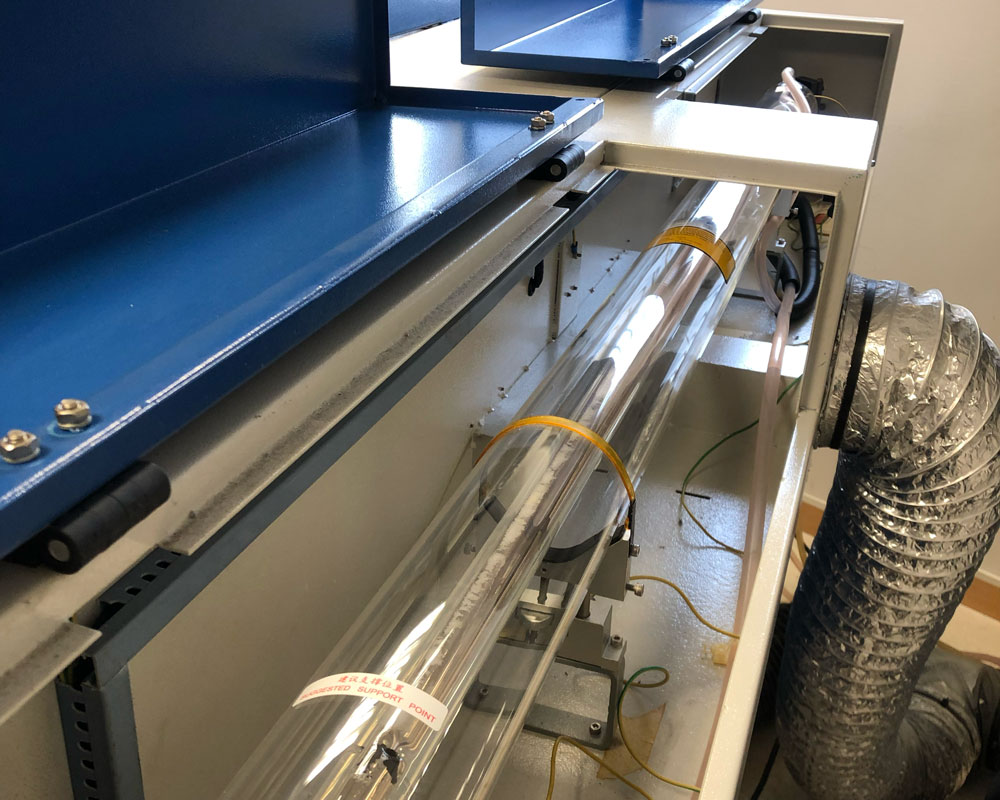
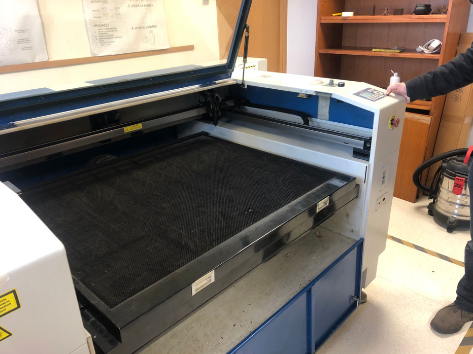
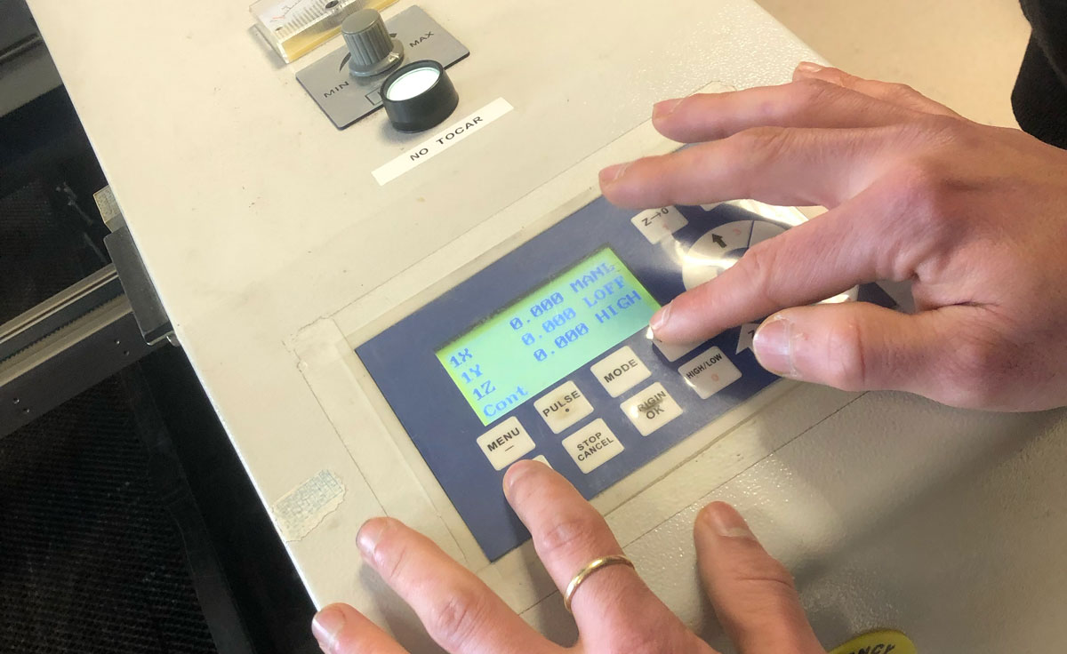
The appearance of the machine is shown in the following image:
The machine operation is carried out through the control panel and the software installed on the computer. The following section presents the structure of the control panel and the corresponding operations.

Mechanical origin (Home): Refers to the position located at the top right of the working area. The machine uses this point to determine the table limits and position itself within it.
Work origin (Origin): Refers to the position where the process starts.
[HOME (9)]: Used to return the laser head to the system’s mechanical origin.
[MENU (-)]: Press “Menu” to view the configuration options. Press [OK] to access the submenu. The second function of this button is (-), used to enter negative values in numeric mode.
[STOP / CANCEL]: Press this button to stop the current job. Once stopped, it is not possible to resume from that point; the job must be restarted from the beginning. The second function of this button is to move up one level when inside a submenu or to cancel during parameter input.
[ORIGIN / OK]: In standby mode, press this button to move the laser head to the user-defined origin, which is the starting point for the job. Within any menu, it is used to enter a submenu or confirm values or parameters.
[PULSE (.)]: When pressed in standby mode, the LASER will activate at low power for a short period (depending on the PULSE Power and PULSE Time settings). As a second function, it is also used as a decimal point when entering configuration parameters.
PROHIBIMOS USARLO PELIGRO EL LASER FUNCIONA con a puerta abierta
[RUN/PAUSE (DELETE)]: Press this button to pause the machine while in operation and press again to resume. When entering parameters, this button is used to delete the last digit entered.
[MODE]: Press this button to set the movement mode of the laser head, selecting from three possible modes: Continuous / Step / Fixed Distance. In distance mode, the desired value must be entered using the numeric keypad.
[HIGH / LOW (0)]: Press this button to select the manual movement speed of the laser head. As a second function, it is also used as “0” (zero) when entering configuration parameters.
[XY-0 (2)]: Used to define the work origin in X and Y. It also serves to enter the value “2” in parameter mode.
[Z-0 (1)]: Used to set the height of the worktable after measuring the focal distance. It also serves to enter the value “1” in parameter mode.
Some buttons have more than one function when combined with others. To use the combined keys, press the first function key and, without releasing it, press the second key to access the second function.
[Menu (-)] + Numeric buttons: This combination selects one of the 9 possible origin points. Note that on the screen, to the left of each coordinate value, the number of the selected origin (1-9) will appear. This is fixed at (0,0) with the 2 key.
[Pulse (.)] + [Z Up (7)] or [Z Down (8)]: Used to modify the LASER power on a job that has already been sent to the machine. The adjustment is made in 5% steps.
[RUN/PAUSE (DELETE)] + [HOME (9)]: Used to enter the file selection menu. Within this menu, you can select between the machine's internal memory or a USB pendrive.
[MENU] + [MODE]: Press these two buttons to switch between the flat engraving mode and cylindrical surface engraving mode. Note that on the machine's screen, the "Y" axis will change to "C" when the rotary mode is selected.
Instructions:
Step 1
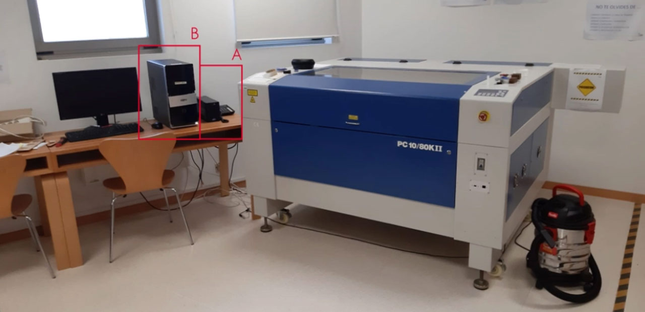
- Turn on SAI System (A)
- Turn on the computer (B)
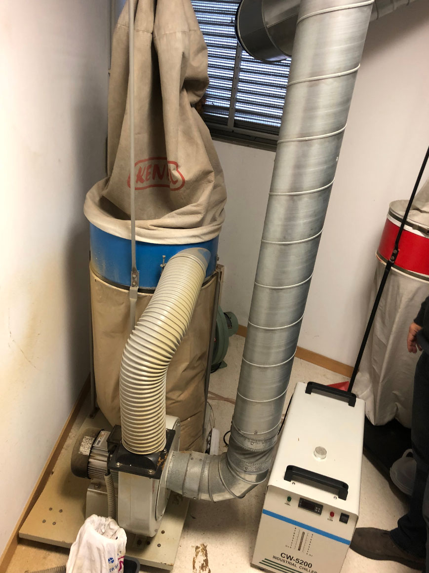
- Next, turn on the refrigeration system:
Step 2
- Check that the bed of the machine is empty by lifting its cover
- Turn on the machine: the screen will display: Go to home?
Only if the head can move freely across the work surface, press the OK button at this moment.
If the lens does not move or respond to a movement command, it means that the memory of the machine need to be reconfigured.
Step 3
- Place the material.
- Move the cursor to the local origin. Use the arrow keys on the panel marked with 3,4,5 and 6, and adjust the movement speed using the (0) key.
- Once the exact position of the origin is determined, press the 2 key.
Step 4
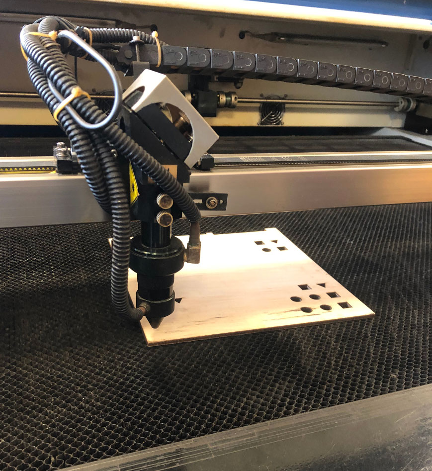
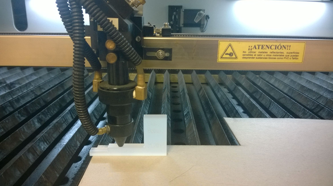
- Adjust the lens height with the gauge.
- Loosen the two vertical screws slightly as shown in the image.
- Place the acrylic gauge and gently tighten (Important) the screws to secure it.
- It is not necessary to tighten them forcefully.
- The height to ensure proper focus is 10mm above the material.
It is important to mention that the screws should be tightened lightly; otherwise, the machine could be damaged.
Step 5
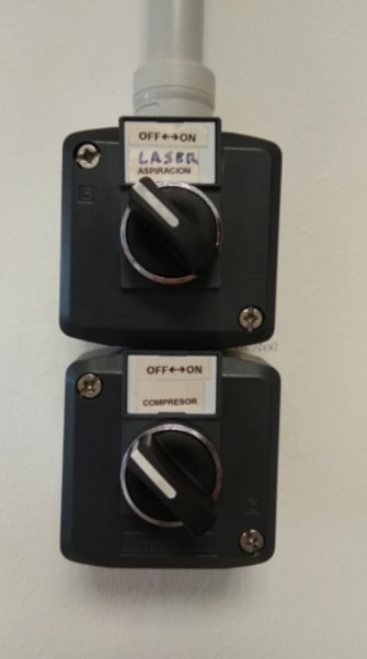
- Turn on the extraction system and the compressor
- Carefully lower the laser cutter's cover.
- At this point, it is very important to check the proper functioning of the cooling system, the air compressor, and the extraction system.
Check NOISE
Ensure that there are no objects on the material that could interfere with the head's movement.
Step 6
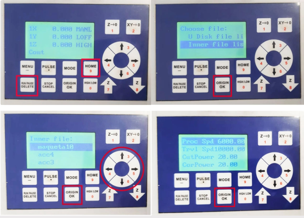
- Press the RUN/PAUSE DELETE key and the HOME key on the panel SIMULTANEOUSLY. Two options should appear. Select the lower option by pressing the down arrow: Inner file list, and press OK.
- Using the movement arrows 3,4,5 and 6, navigate to your file and press OK, then confirm by pressing OK again.
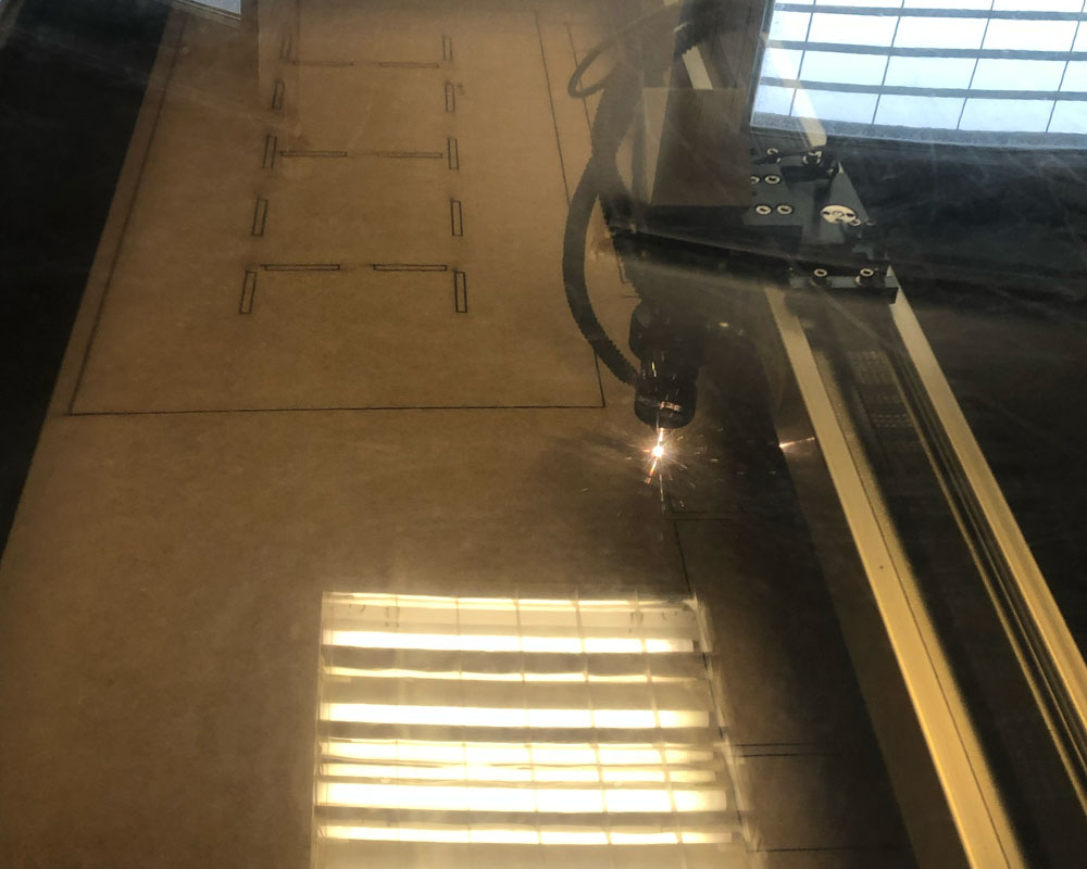
The cutting process will begin. Ensure that the extraction and ventilation systems are functioning properly.
Monitor the machine's operation at all times.
In case of fire, immediately open the cover and move the head away from the hot spot by pressing the movement arrows 3,4,5 and 6. The fire should extinguish quickly. If this is not the case, there is a fire extinguisher to the right of the machine.
We have a water bottle that allows us to extinguish the combustion of the material if necessary.
When the process is finished:
Step 7
After the cutting is finished, and before removing the material, move the head away from the work area. Do so manually by pressing the movement arrows 3,4,5 and 6.
Step 8
Remove any excess material, vacuum any remnants that may remain on the surface, and leave everything turned off and tidied up, just as you found it.
CorelDRAW
Prepare your file in the following vector formats:
- .dxf; .dwg AutoCAD version 2010
- .dxf AutoCAD version 2000 (only simple drawings)
- .cdr (Corel Draw X3)
- .svg
- .crv Vcarve
- Other programs: 123D Mak, Rhinoceros 3D + Grasshopper, Open Source, Librecad, Inkscape, Freecad.
Layer System
Draw your files as follows:
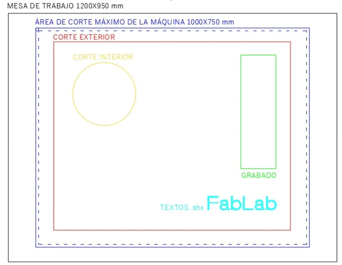
- Draw in BLUE and in landscape orientation the size of the material to be cut, with a maximum size of 1000x750mm. Leave a free space of 60x100mm in the top-left corner. Leave a 10mm margin on the edges.
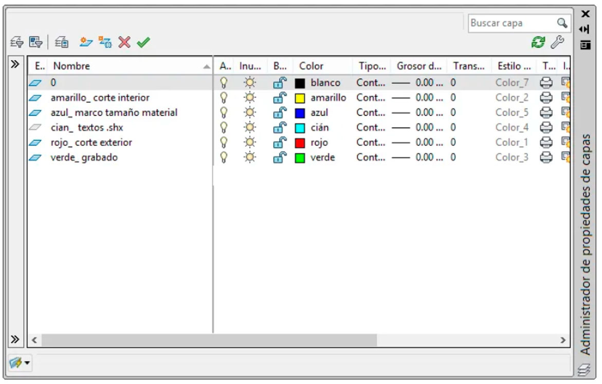
Draw the elements to be cut according to these colors and layers, inside the previous box (no layers other than the ones indicated should exist; all layers must be active and unlocked. They should only contain the objects and entities to be processed):
- 0: Empty. Not used.
- Red (1): Used for exterior cuts.
- Yellow (2): Used for interior cuts.
- Green (3): Used for engraving.
- Cyan (4): Used for text and markings. Note: Use .shx fonts for text and marking, do not use .ttf.
- Blue (5): Used to define the outer frame.
The layers correspond to both the type of cut (cutting, engraving, filling) and the order in which they should be executed (we will name them in the order they should appear in Corel, from top to bottom).
*** Never bring shading from AutoCAD; the fill pattern should be drawn directly in CorelDRAW on the FabLab computer.
Step 1
If you bring your file in .dwg 2010 or .dxf 2000 format:
Better format SVG
- Open CorelDRAW X3 and import file
Step 2
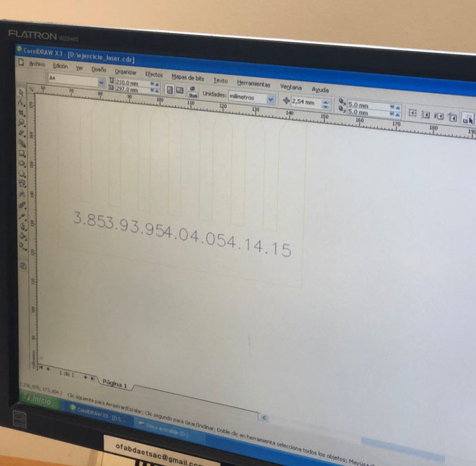
- Dimension the size of the figure in CorelDRAW X3 to match the real dimensions in mm.
- Don't worry about the A4 image that appears; the drawing will scale to the full size defined by the outer contour of the drawing.
Step 3
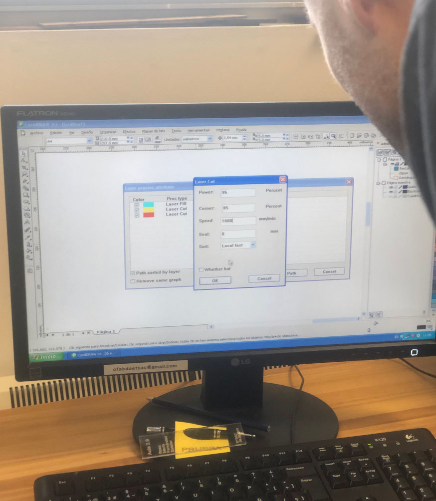
Laser Parameters:
- Set the power and speed values according to the type and characteristics of the job.
- Use the Laser Cut option when cutting the material. Use the Laser Fill option when doing hatch or shading.
For Laser Cut, fill in POWER, CORNER, and SPEED based on the values in the materials table.
- Power refers to the laser power for straight sections.
- Corner refers to the laser power for curves.
For Laser Fill, complete POWER, SPEED, FILL SPACE (distance between lines forming the pattern), and ACCEL DIST (distance at which the pattern starts, usually 5 mm).
Refer to the materials table for the values.
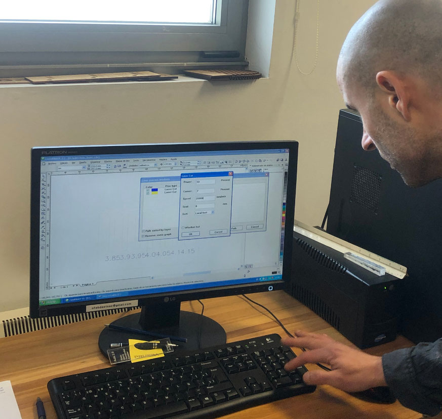
For the BLUE layer, always use these parameters:
- Power: 1
- Corner: 1
- Speed: 20000
Step 4
Reorder the layers from top to bottom in the following order:
a. Board contour (blue)
b. Labeling (cyan)
c. Engraving (green)
d. Interior cut (yellow)
e. Exterior cut (red)
Step 5
- Check the box Remove same graph.
- Ensure the cutting machine is on and press PATH.
Step 6
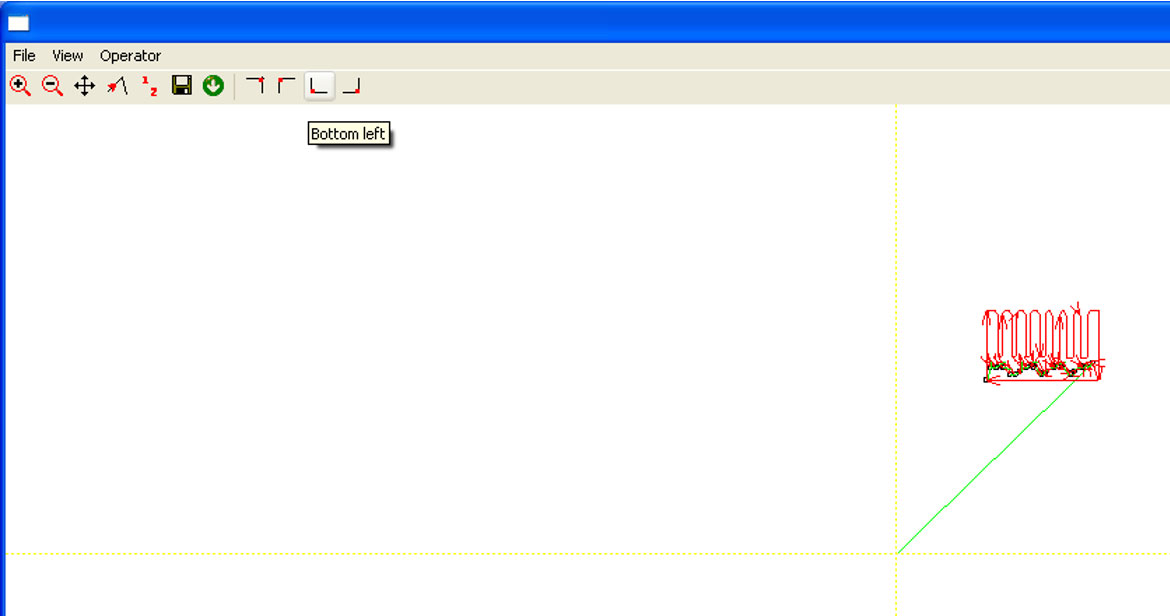
- Select the cutting origin in the top menu, which should align with the material placement on the machine. We recommend choosing the bottom-left corner whenever possible.
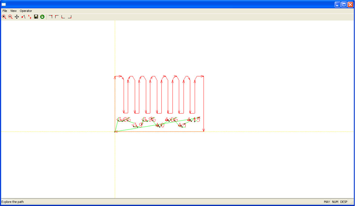
- It’s a good practice to review the laser paths; use the Frame and Zoom +/- buttons.
- Finally, click the green circle with the white downward arrow to send the GCODE to the machine.
Important:
The next two steps are critical. If not done correctly, you could reset the machine’s settings.
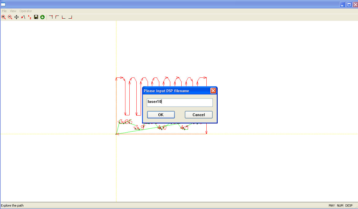
- Name your work and press OK.
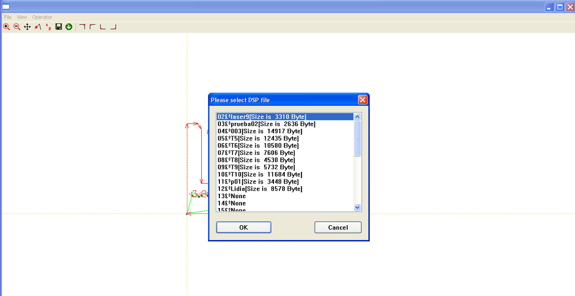
- Select a memory position and press OK.
- If you don’t follow this step precisely, the machine will stop responding. Don’t worry; notify us to restore its settings.
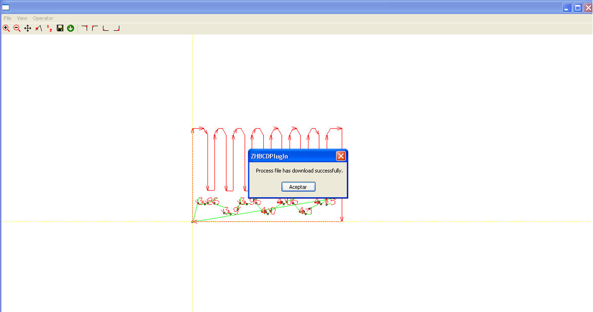
Note:
If "Process file has downloaded successfully" doesn't appear, try disconnecting and reconnecting the USB cable between the computer and the machine.
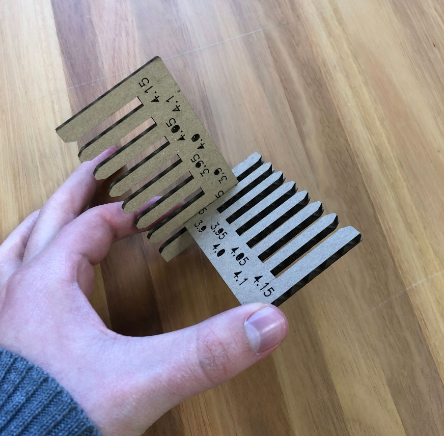
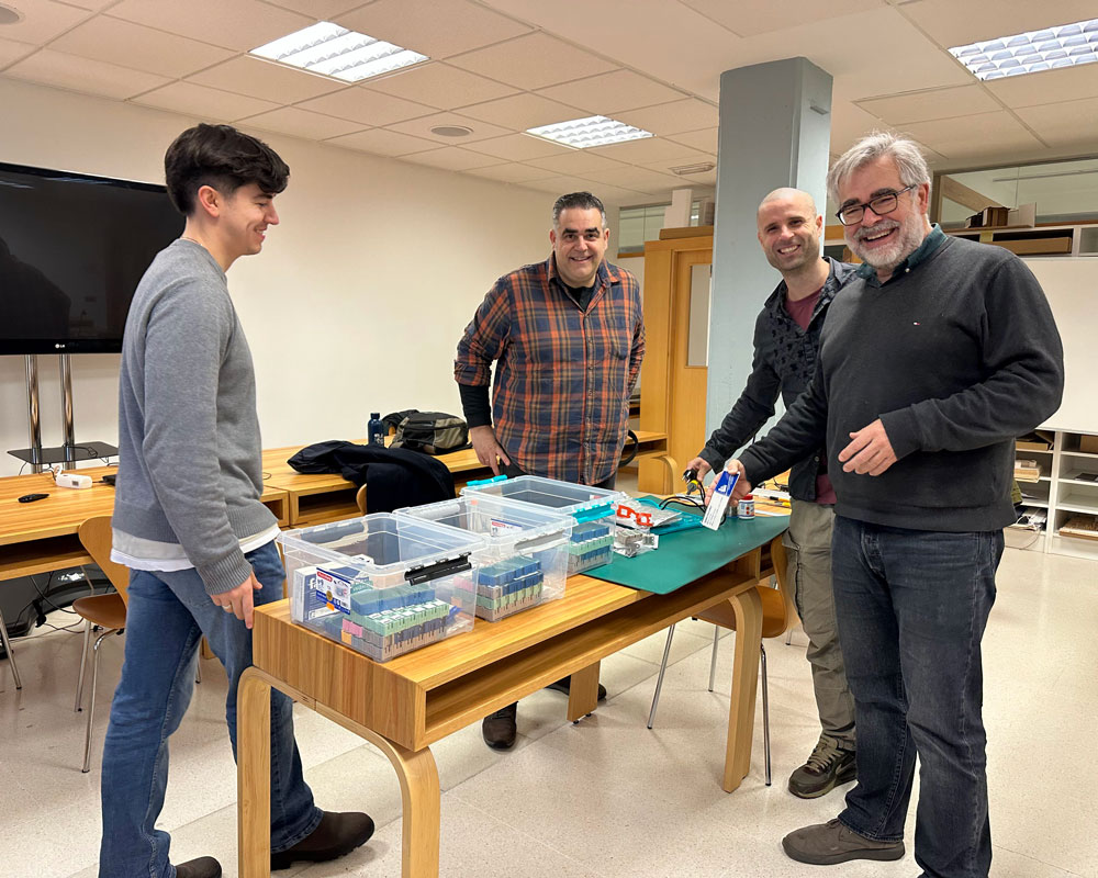
Afterwards, we conducted an activity to characterize the parameters for the machine.
First, each of us created a parametric kerf, which can be seen on each student's personal page.
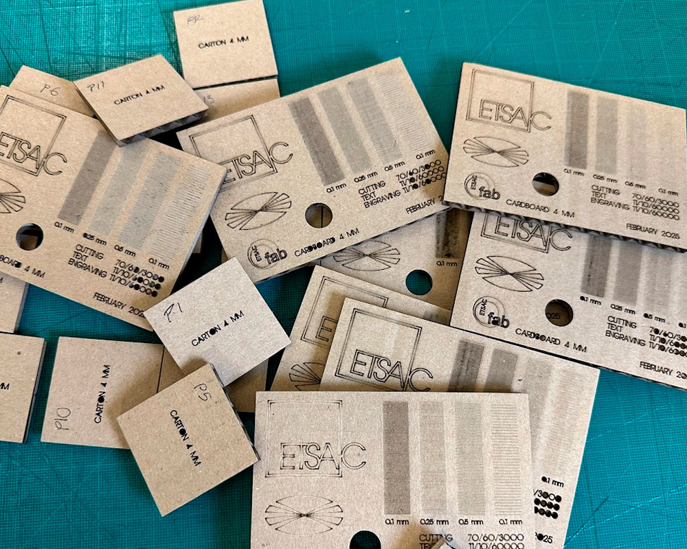
You can see all the attempts we made here in the board:
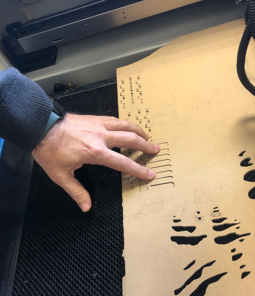
But finally we got:
| Material | Task |
Thickness (mm) |
% Power Straight |
% Power curve |
Speed |
Cardboard |
Cutting |
2 |
40 |
35 |
3000 |
|
Engraving |
2 |
15 |
13 |
35000 |