Week 08
Electronics production
Group assignment
- Characterize the design rules for your in-house PCB production process: document feeds, speeds, plunge rate, depth of cut (traces and outline) and tooling.
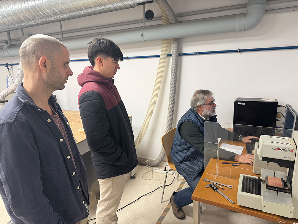
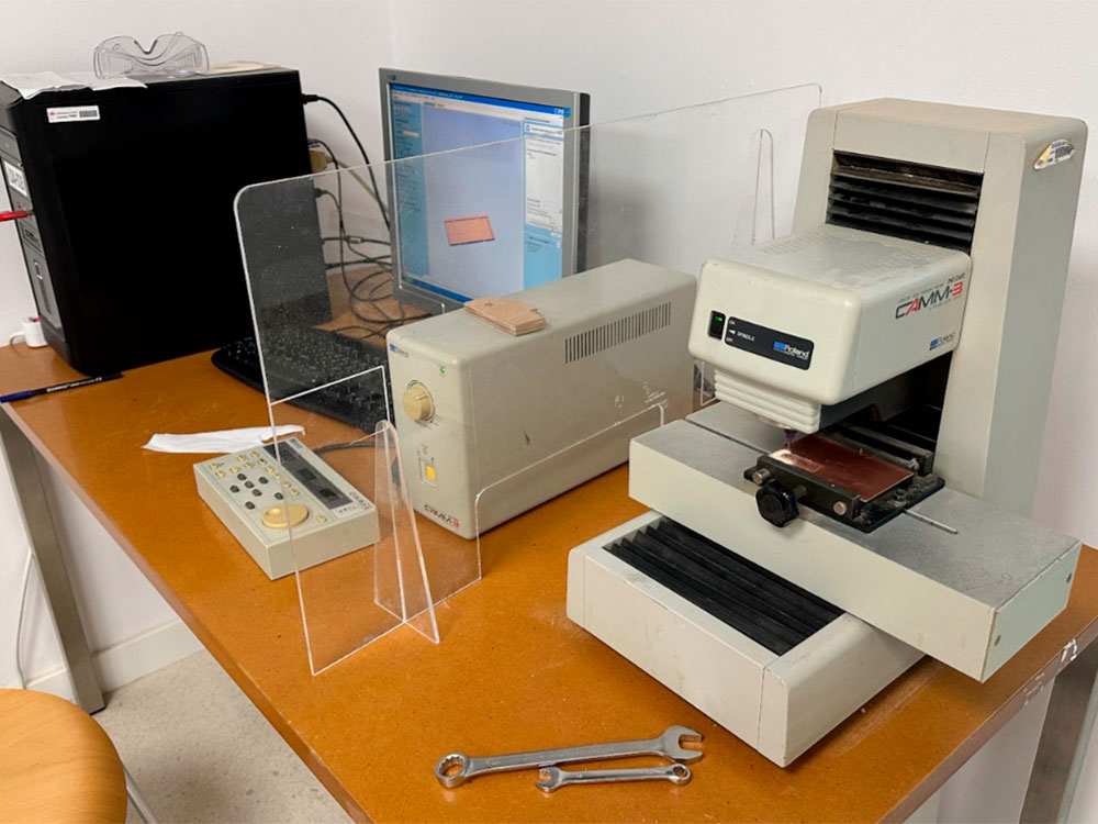
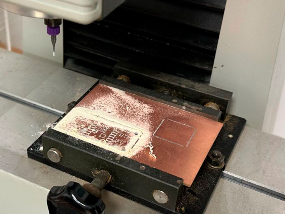
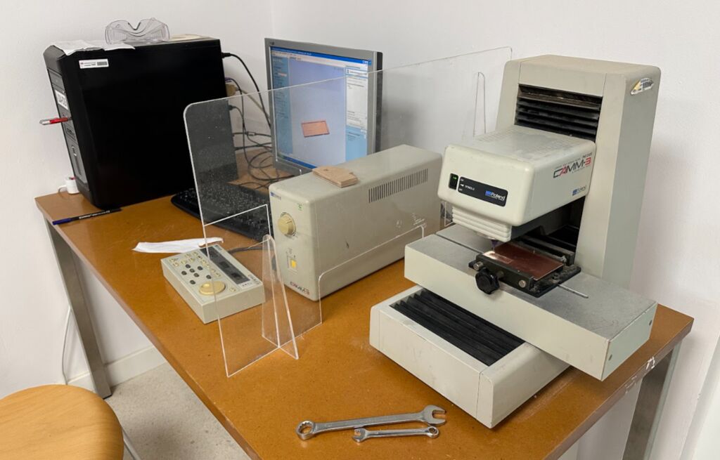
Once we had our pcb boards ready to cut we use the Roland CAMM PNC-2500 to fabricate our PCB and Pepe explain the rest of the group how it works.
TECHNICAL DATA SHEET
MILLING MACHINE “ROLAND CAMM PNC-2500”
DESCRIPTION
FEATURES
- XY Table Size: 500 x 170mm
- Maximum Work Volume (X/Y/Z): 250 x 150 x 150mm
- Software Resolution: 0.01 mm/step
- Mechanical Resolution:0.00125 mm/step (micro-step control)
- Axis Speed: X, Y: Max. 60 mm/sec, Z: Max. 30 mm/sec
- Spindle Motor Power: 180W
- Rotation Speed: 3000—8000 rpm
- Operating Temperature: 5—40°C (41—104°F)
- Operating Humidity: 35%—80%
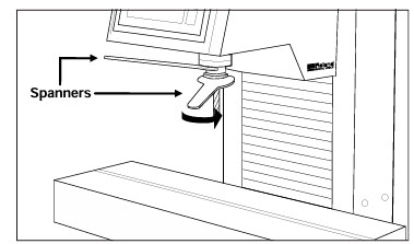
Spanners for tool attachment: 30mm, 22mm
PCB – Milling Machine
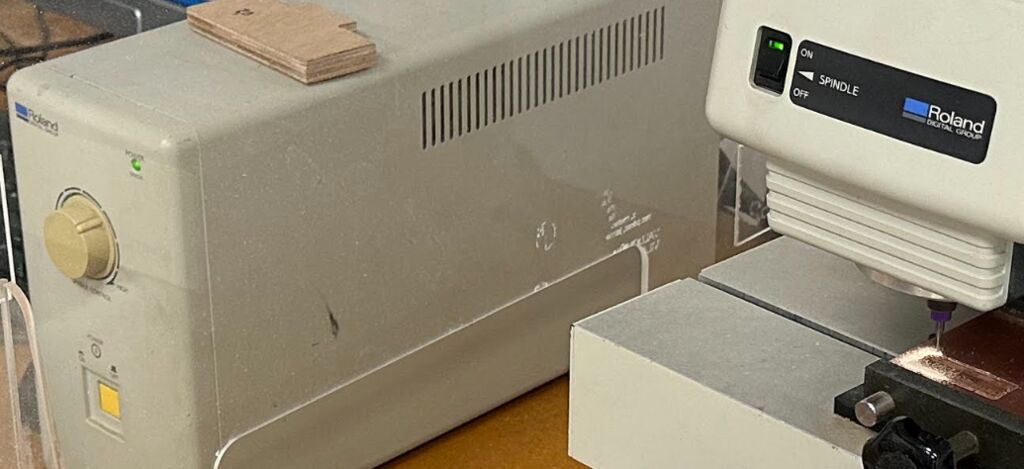
At our FabLab, we have two Roland PNC-2500 milling machines. These are discontinued models with many years of use but still function correctly and fulfill their purpose.
Speed control is performed manually by turning the jog dial. The maximum rotation speed is 8,000 rpm.
ONLY ONE PERSON OPERATES THE MACHINE!
USE PROTECTIVE GEAR: GLASSES – HELMETS – GLOVES
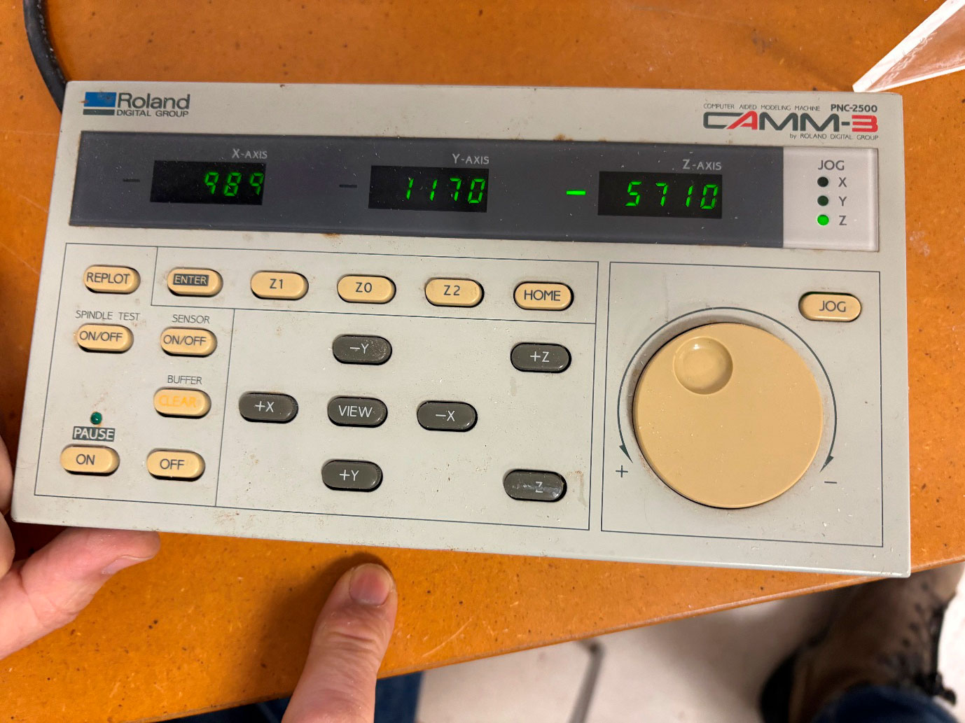
Switch panel:
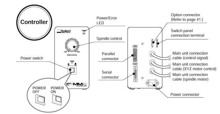
Controller:
XYZ Coordinate Display |
This display shows the coordinate values of each axis in 1/100 mm units. For the X and Y axes, the home position coordinates are (0, 0). For the Z axis, Z0 is displayed as "0." |
REPLOT Key |
This keys carries out replotting (recutting) when cutting data is present in the PNC-2500 data buffer. |
ENTER Key |
In combination with the [Z0] , [Z1] , [Z2] and [HOME] keys, the key designates the positions of Z0, Z1, Z2 and HOME. Also, if this key is pressed when PAUSE is ON, the moving speeds in each axis direction are shown on the XYZ coordinate display. |
Z Axis Position Keys |
These keys are used to set the positions of Z0, Z1 and Z2 in combination with the [ENTER] key. Also, the tool is moved to the ZO, Z1 or Z2 position when the appropriate key is pressed. In the interests of safety, movement to Z1 does not begin until the [Z1] key is pressed for 0.5 seconds. |
HOME Key |
This key is used to set the HOME position (refer to page 14) in combination with the [ENTER] key. Also, if you continue pressing this key for approx. 0.5 seconds, the tool is moved to the HOME position. |
SENSOR Key |
In the case that Z0 setting is performed using the optional sensor, this key functions as the sensor ON/OFF switch. |
VIEW Key |
If this key is pressed for 0.5 seconds or more, the spindle raised and the XY table moves toward the front of the unit and stopped. |
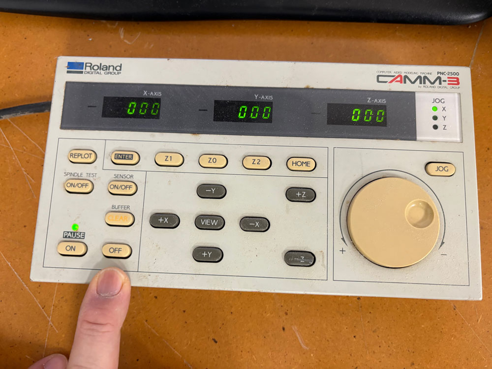
PAUSE Keys |
When the [PAUSE ON] key is pressed while operating under the instruction of a computer, the PAUSE LED comes ON and the PNC 2500 enters the temporary stop condition and all cutting operations are interrupted. When the [OFF] key is pressed, the temporary stop condition is cancelled and machine resumes cutting from the posi tion at which operation was interrupted. |
PAUSE LED |
This LED comes ON when the PNC-2500 enters the temporary stop condition as a result of the [PAUSE ON] key being pressed. This LED goes OFF when the temporary stop condition is cancelled by pressing the [OFF] key. |
BUFFER CLEAR Key |
If this key is pressed for 0.5 seconds or more, erasing all data transferred from the computer. |
SPINDLE TEST ON/OFF Key |
When this key is pressed while the spindle revolution stops, the spindle is forced to rotate. When this key is pressed while the spindle is revolving, the revolution stops. |
JOG Keys |
These keys move the tool in the + or - directions along the X, Y and Z axes. Perform rough position using these keys and then make delicate adjustments to the tool position using the jog handle. The tool moves approx. 30 steps (0.3 mm ( 0.12")) each time a key is pressed. The jog handle can move the tool one step (0.01 mm (0.00039")) at a time. Holding down the jog key for the X or Y direction allows rapid movement in that direction when the spindle is not rotating. Because X, Y and Z movements are independently controlled, the keys for movement along each axis can be pressed simultaneously. In this manual, the Z-axis Jog key is represented in [ (Z) ] or [ (-Z) ]. |
JOG Handle |
This handle moves the tool position on the X, Y or Z direction in units of 1 step (0.01 mm (0.00039")). Select the axis along which movement is desired using the [JOG] key. The jog handle can then move the tool along the selected axis |
JOG Handle Select Key |
This key is used to select the axis along which the jog handle moves the tool. This key is referred to as the [JOG] key in this manual. |
JOG Handle LEDs |
These LEDs provide an indication of the currently selected jog handle axis. |
Cutting Tool Attachment
- Set the SPINDLE switch on the front of the PNC-2500 to OFF. • The LED lamp in the SPINDLE switch flashes. (When power is applied.)
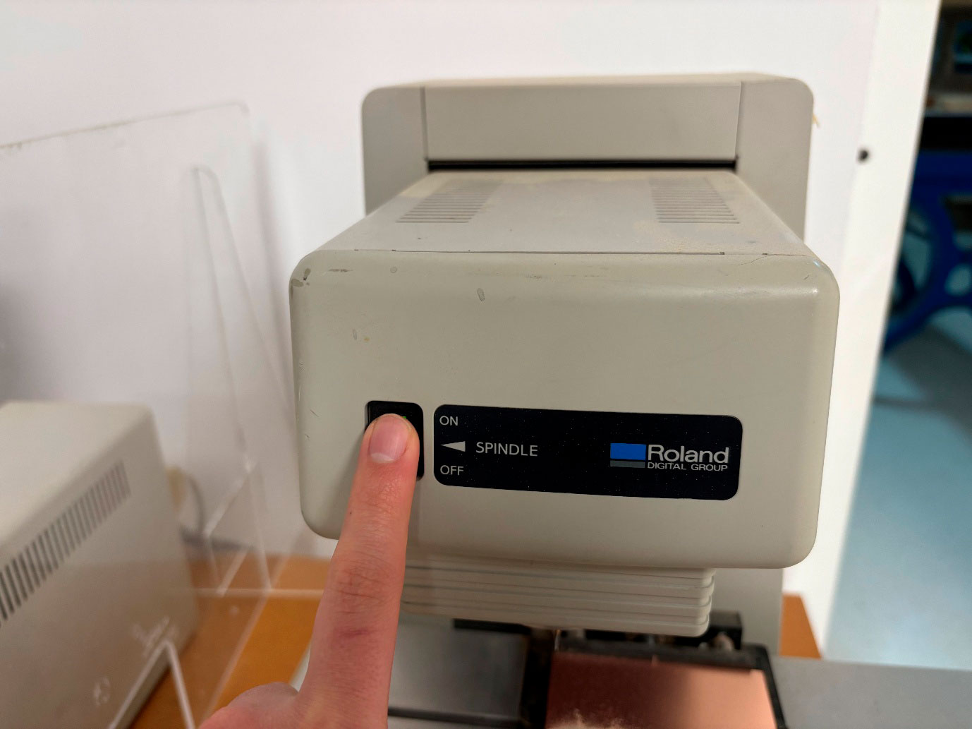
- If a cutting tool has been installed, remove it. Use the two spanners provided to loosen the collet cap.
• To keep the cutting tool from falling out, loosen only slightly.
• After loosening, then loosen the cap by hand and pull out the cutting tool.
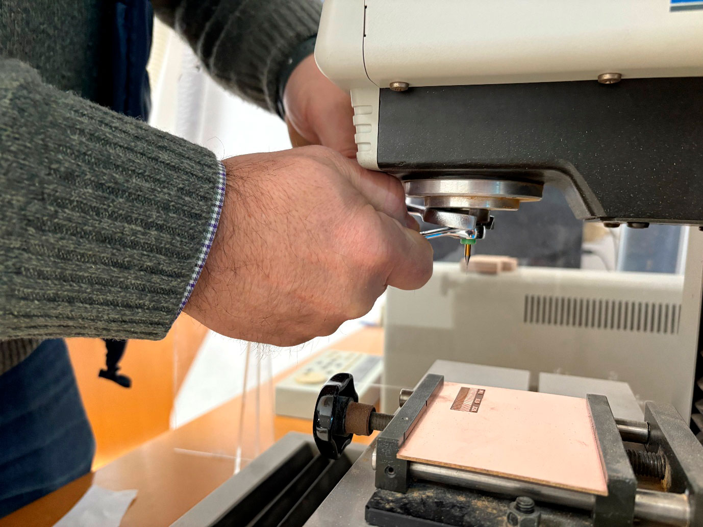
- Adjust the height of the inserted tool as needed and tighten the collet cap by hand.
•Tighten the cutting tool enough to prevent it from falling out.
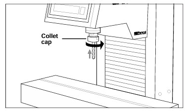
- Tighten the collet cap using the two accessory spanners. Securely fasten the cutting tool to the spindle.
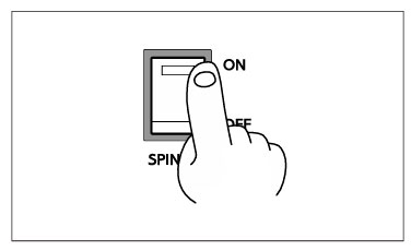
- Set the SPINDLE switch to ON.
• The LED lamp in the SPINDLE switch lights up. (When power is applied.)
Setting the Cutting Origin
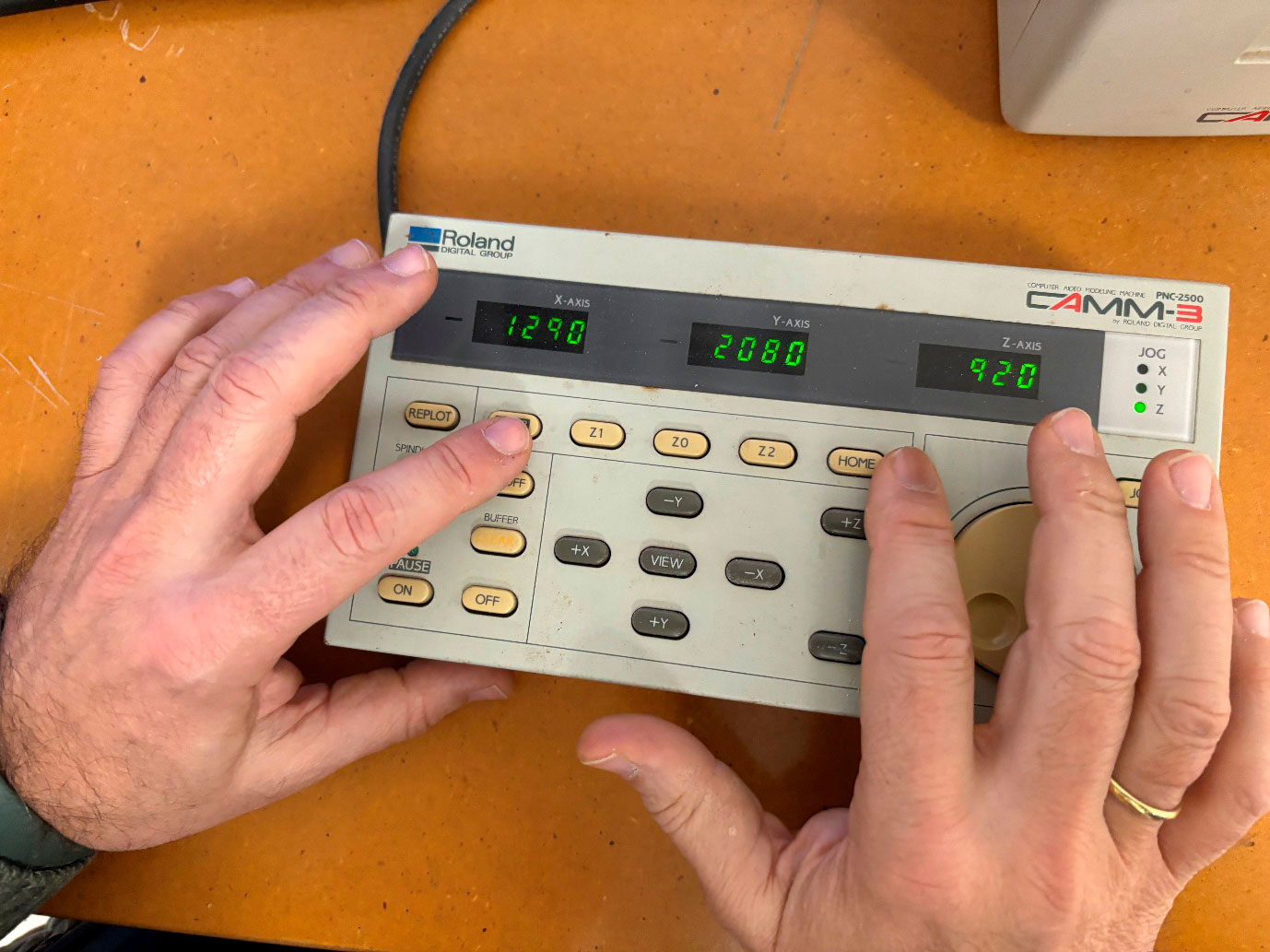
- Home position
1) Move the cutting tool tip close to the lower (nearest operator) left corner of the workpiece, using the jog keys.
2) Move the tool little by little with the [JOG] key and the jog handle. • Line up the cutting tool tip with the lower left corner of the workpiece.
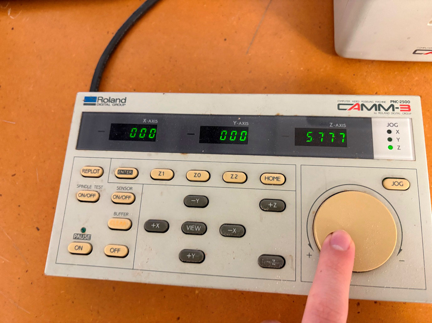
3) Press the [ENTER] key while pressing the [HOME] key.
• Both the X and Y axis indicators on the coordinate display are displayed as "0". • Once the home position is registered in the PNC-2500 it remains in the memory even when the power is turned off. The home position point will remain registered in the memory until a new home position setting is made.
Setting Z0 position
1) Move the cutting tool tip close to the surface of the workpiece, using the jog keys.
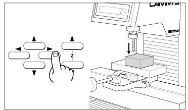
2) Select the Z axis with the [JOG] key and move the cutting tool a little bit at a time with the jog handle.
• Line up the cutting tool tip with the surface of the workpiece.
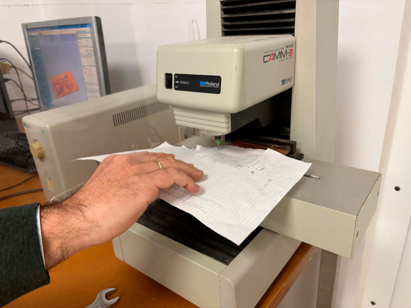
Put a piece of paper to know when the tool is touching the PCB.
3) Press the [ENTER] key while pressing the [Z0] key. • The Z axis indicator on the coordinate displays are displayed as "0".
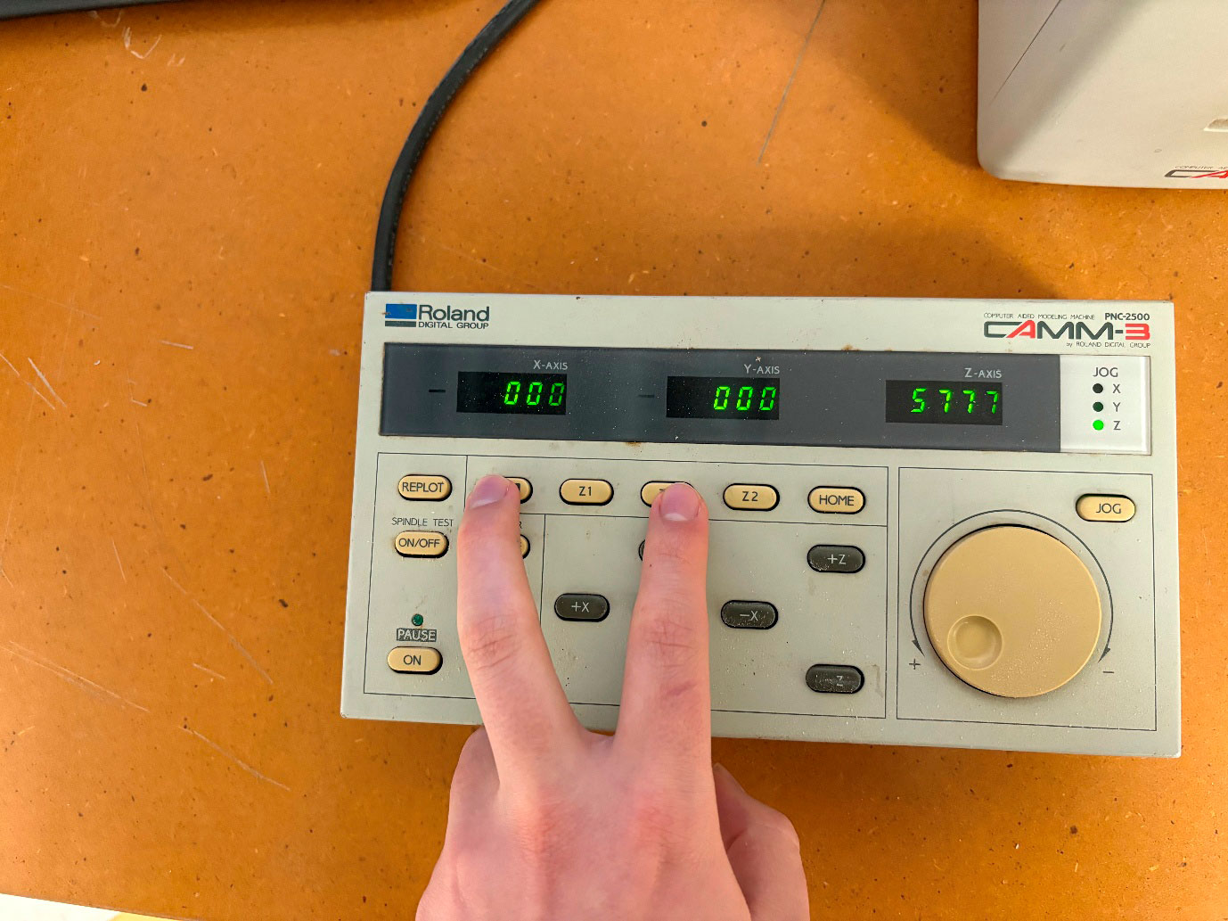
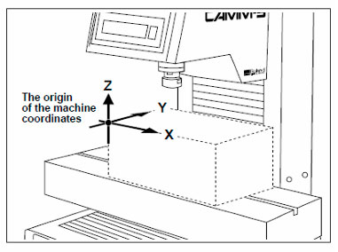
Machine coordinates:
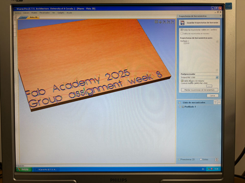
Send the program to the Roland
Press the button “mandar trayectoria de herramienta”
Then press off to quit the pause
Finishing
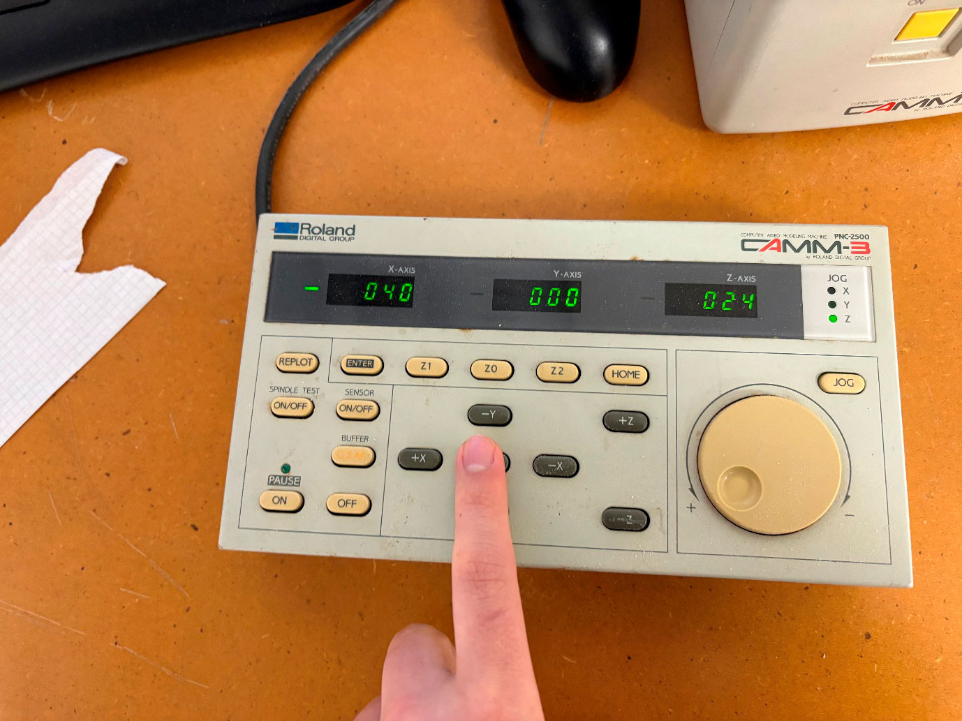
1) When all cutting operations are complete press the [VIEW] key for at least half a second.
• Raise the cutting tool, move the XY table to the outer left (close to operator) and stop it.
• When the spindle is still rotating, press the [SPINDLE TEST ON/OFF] key in order to stop it. • After turning off the power, removal of the workpiece and cutting tool will be easier now that the spindle has been moved out of the way.
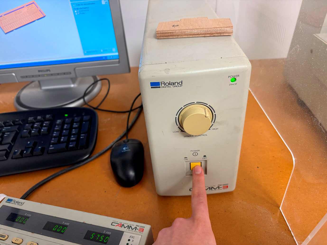
2) After the power to the computer has been turned off, turn the power to the PNC-2500 off.
• The POWER/ERROR LED turns off. • Next remove the completed workpiece and the cutting tool.
• Store the cutting tool that was just removed, carefully so it will be ready for use when needed.
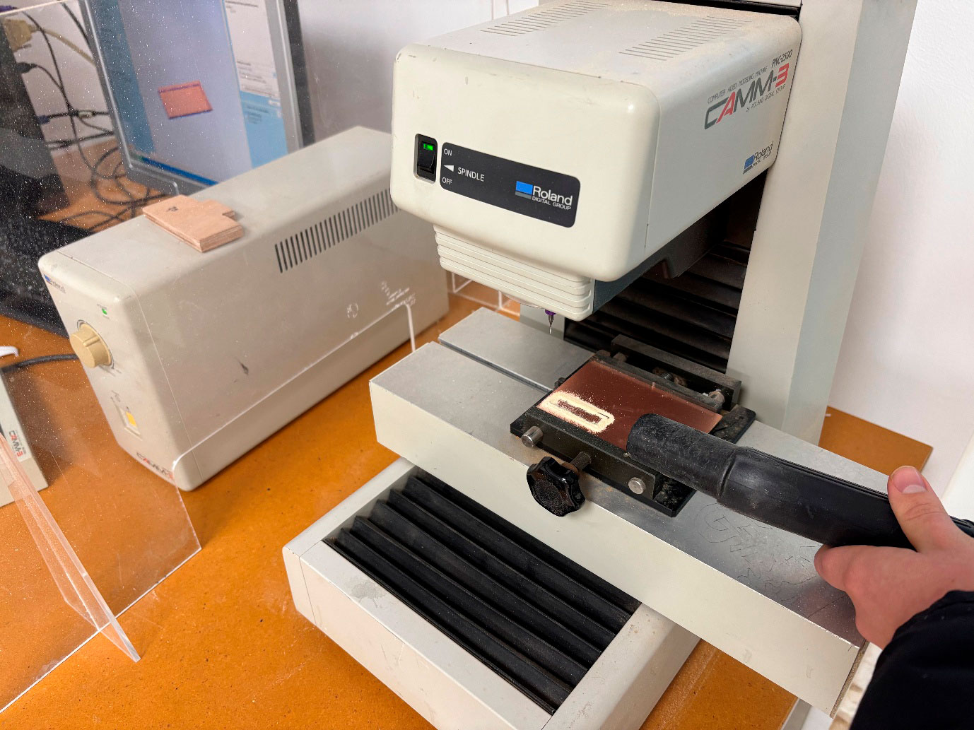
3) Use an appliance such as a vacuum cleaner to remove cutting chips and grit from the machine and surrounding area.
• Do not use an compressed air for such cleaning. Cutting chips in the air may attach to a portion of the machine and cause malfunctions or breakdowns.
• Be especially careful to remove the cutting waste from around the pleated part of the bellows cover.
• Keep the PNC-2500 and its accessories in neat and proper order and use care to ensure normal work operations are carried out safely.
Spindle Motor Revolution Speed
The spindle
motor revolution speed can be set by turning the spindle control knob on the
controller.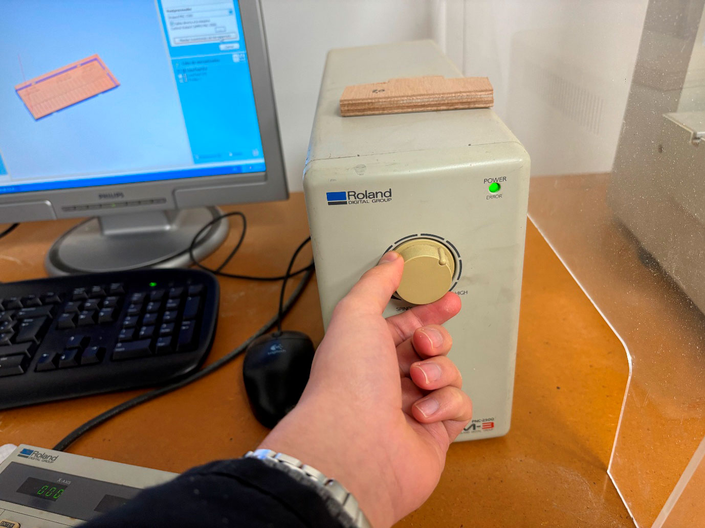
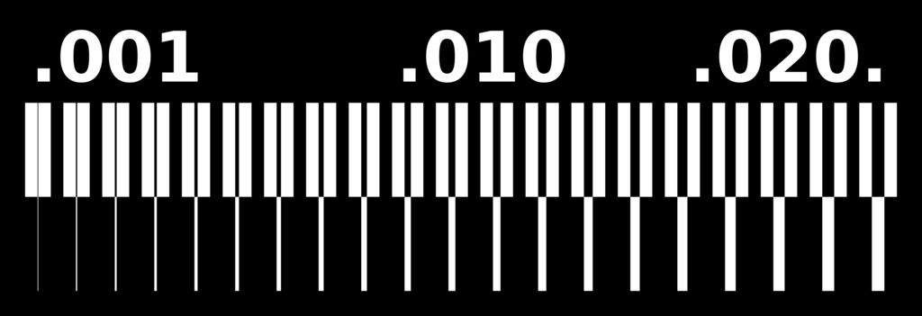
TEST FILES
Traces
Outline

WORKFLOW
Preparing Files
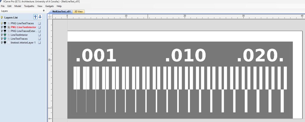
- Job Setup: Size 40 x 15 mm
- Import PNG files into VCarve Pro and trace bitmap
- Organize layersin VCarve for better machining management
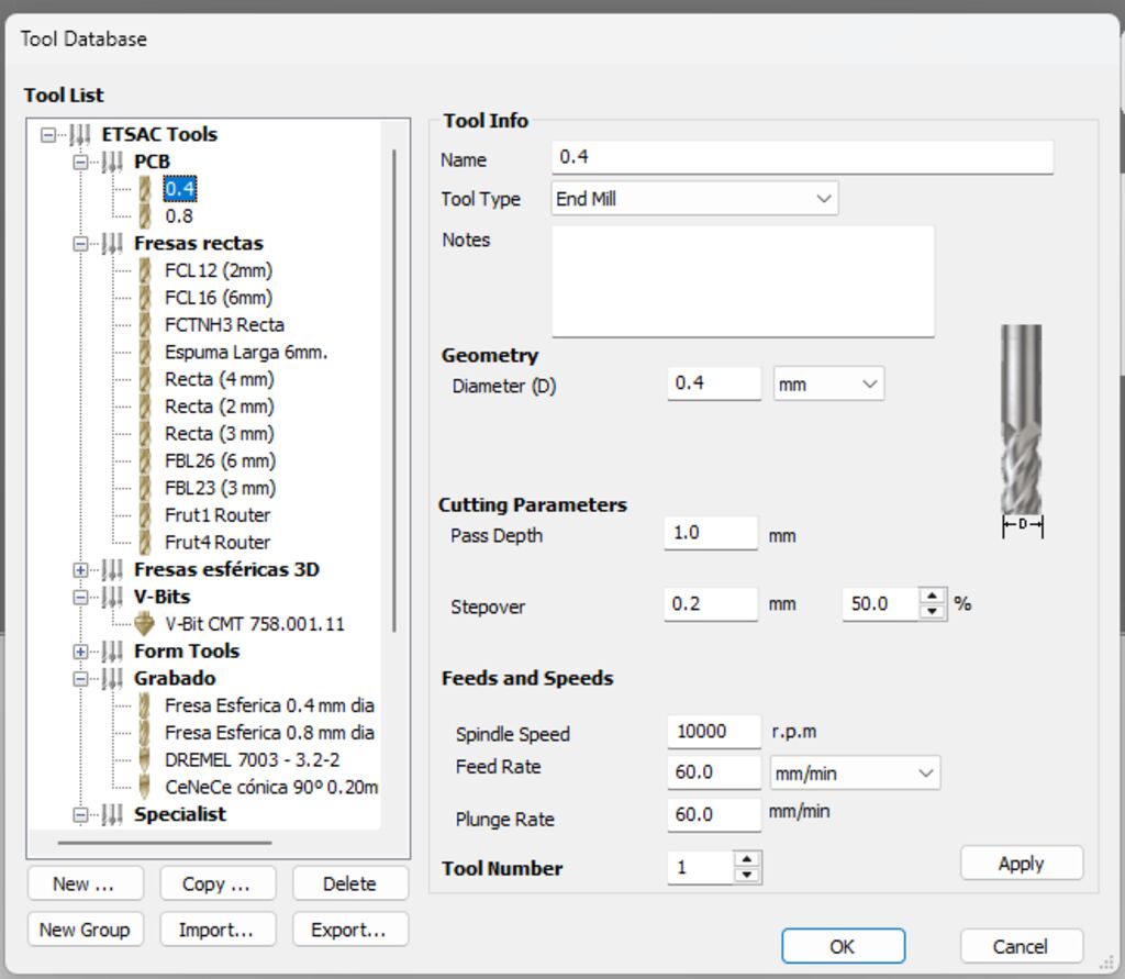
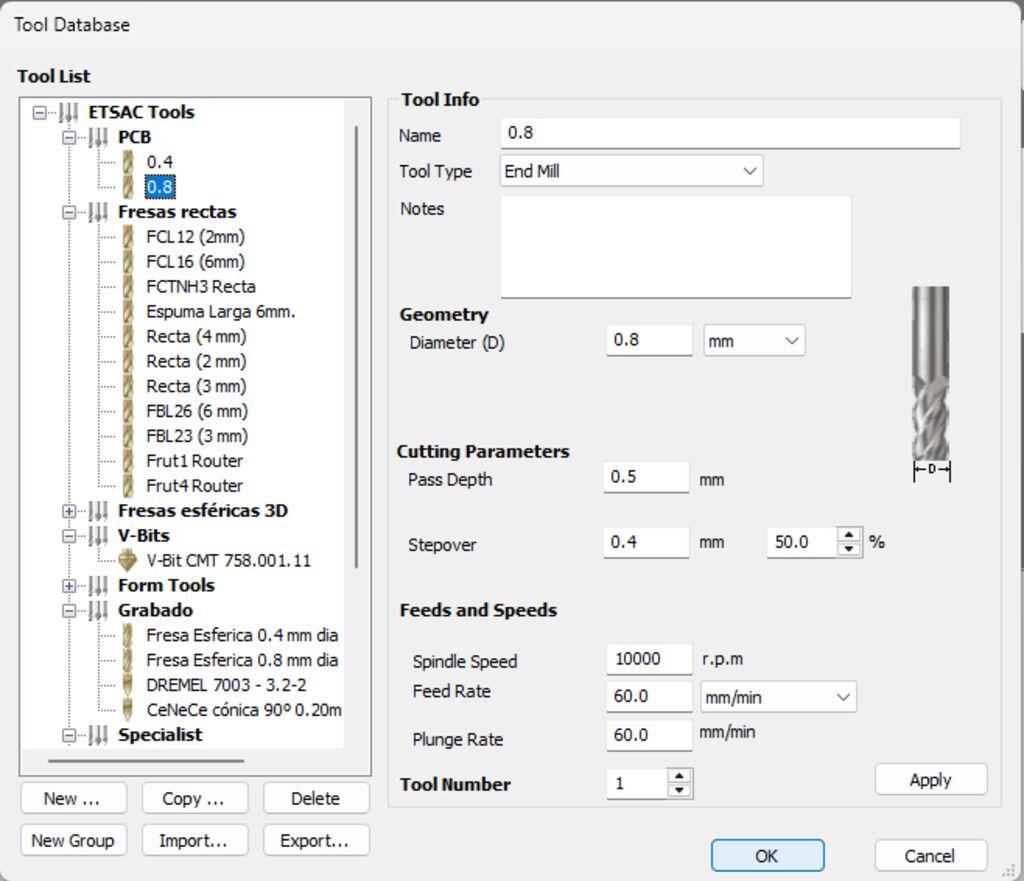
Defining Tools
|
|
|
|
Set feed rate 60 mm/min Plunge rate: 60 mm/min |
Set feed rate 60 mm/min Plunge rate: 60 mm/min |
Feeding Speed
The machine's feed rates depend on the material, cutting depth, and safety margin to avoid tool breakage. We have selected:
- Set feed rate: 60 mm/min
- Plunge rate: 60 mm/min
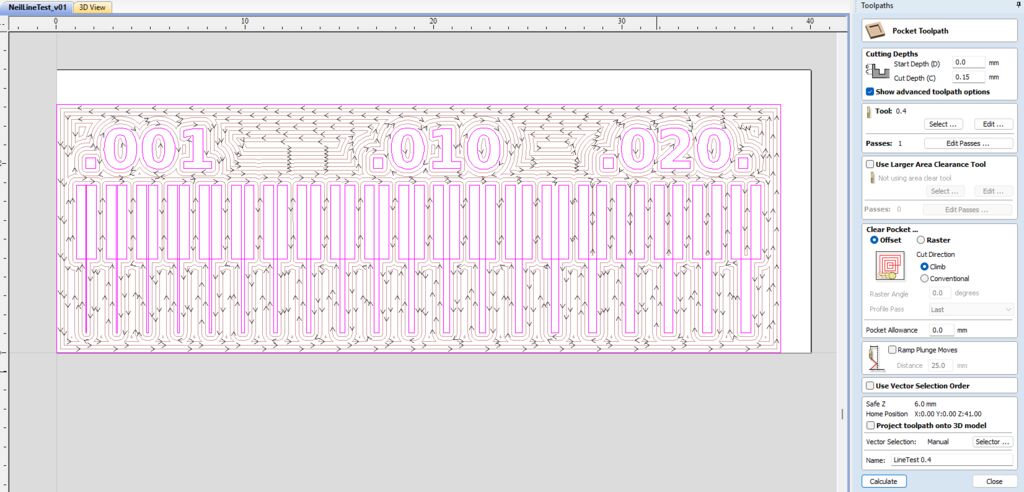
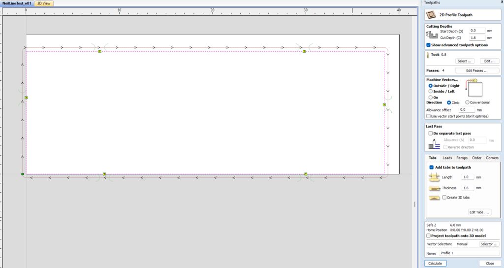
Defining Toolpaths
Previewing the Job
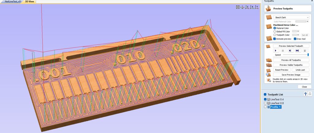
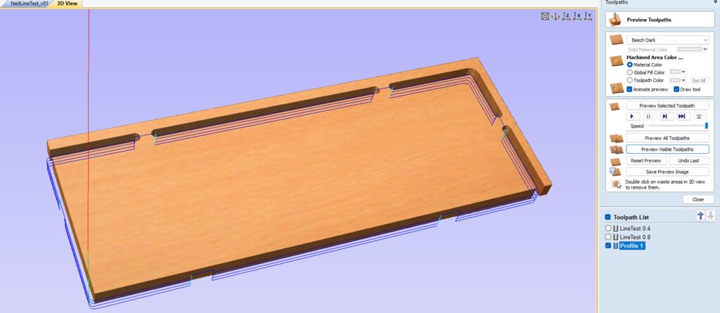
IMPORTANTTo stop an incorrect job on the milling machine: Press Pause ON, hold the Buffer Clear key for more than 0.5 seconds, and then press Pause OFF |
Milling
- Set XY Origin: Enter + Home
- Adjust Z0: Enter + Z0
- Spindle Speed
Insert:
LineTestTraceCutLineTestEdgeCut
Result
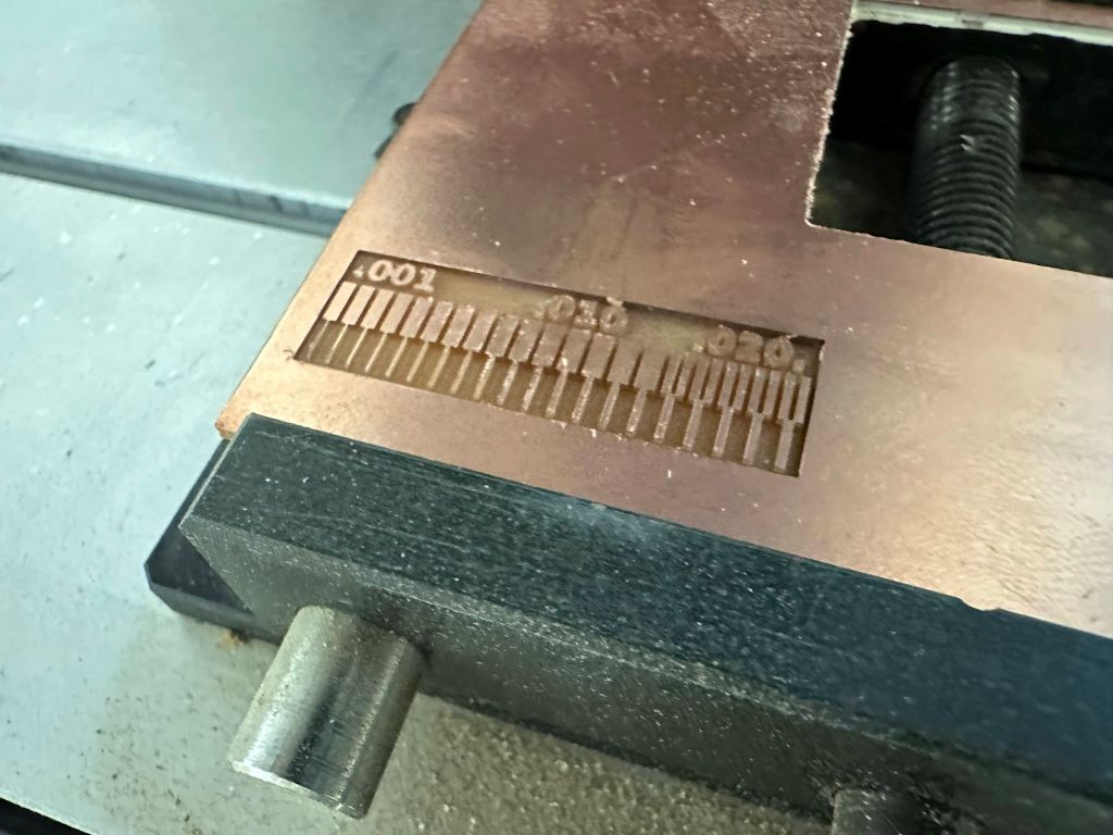
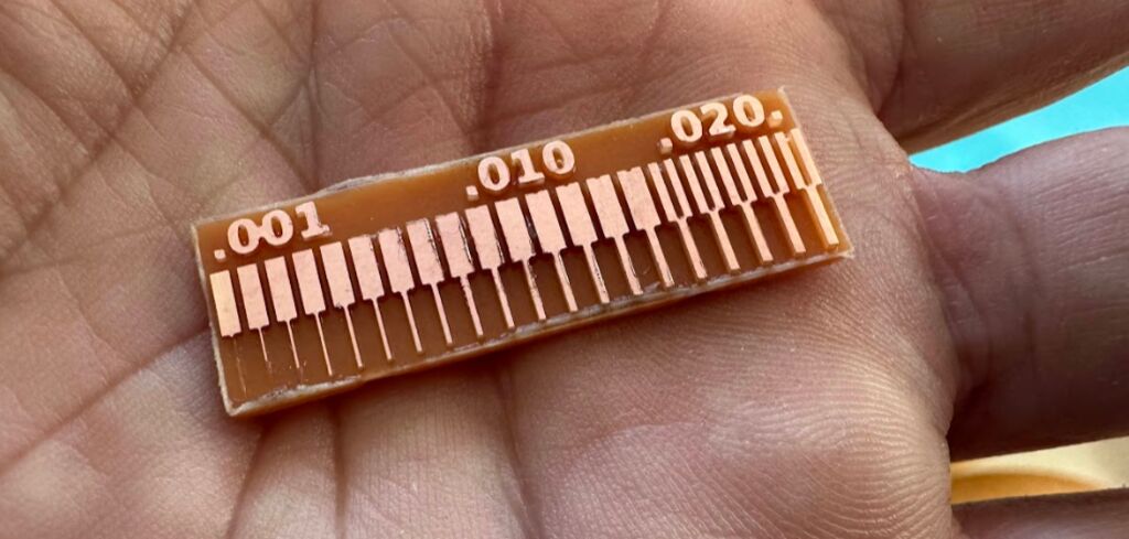
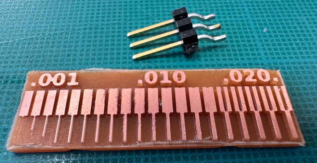
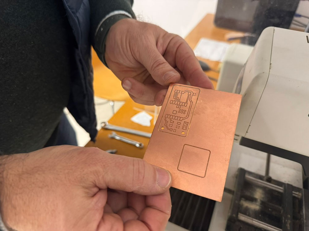
We increased the feed rate to 80 mm/min while maintaining 60 mm/min for the plunge rate and repeated the test.
Since speed control in this machine is manual, based on the results of the previous test, we increased the speed by turning the control knob to the position shown in the image.
With this new configuration, the result quality improved, and the 0.4mm tool did not break.
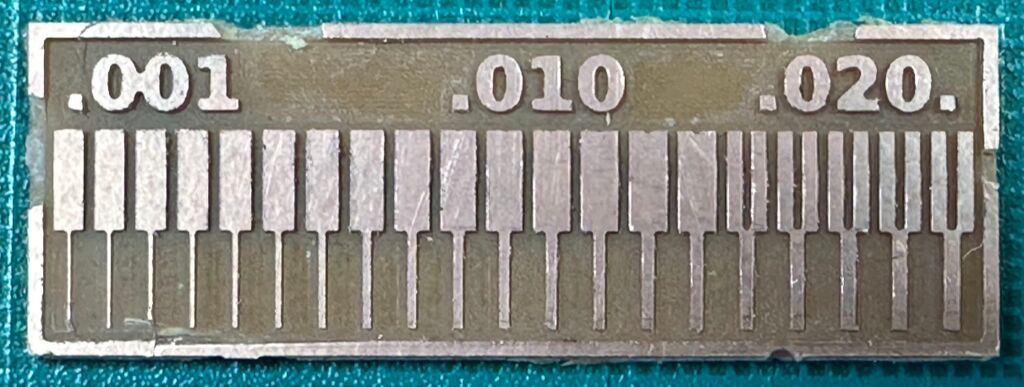
File: NeilLineTest.crv

