14. Networking and communications
Hero shot
Group Assignment
- Send a message between two projects.
Here is a group assignment link
The group assigment link is also attached below.
Individual Assignment
- Design, build, and connect wired or wireless node(s)with network or bus adresses and local input &/or output device(s).
Individual Assignment work flow:
1. Introduction to I2C protocol.
2. Securing connection between boards using I2C.
3. Install a program into the Master board.
4. Install a program into the second board.
5. Run the program and observe if the communication has been established between the two boards through the I2C Bus.
6. Debug where necessary.
This week we learned many networking Protocols that we can plan to use for networking and communication. You can find the page using the following link
So, for this asssignment I choose to use I2C protocol.
To be begin with, I started with learning about I2c procol, how to use it between two Microcontrollers, and how to program them.
So, let us begin with the introduductio to an I2C.
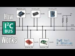
INTRODUCTION TO I2C COMMUNICATION
“Inter-Integrated Circuit” communications(I2C)

With I2C, data is transferred in messages. Messages are broken up into frames of data. Each message has an address frame that contains the binary address of the slave, and one or more data frames that contain the data being transmitted. The message also includes start and stop conditions, read/write bits, and ACK/NACK bits between each data frame:

Start Condition: The SDA line switches from a high voltage level to a low voltage level before the SCL line switches from high to low.
Stop Condition: The SDA line switches from a low voltage level to a high voltage level after the SCL line switches from low to high.

SDA (Serial Data) – The line for the master and slave to send and receive data.
SCL (Serial Clock) – The line that carries the clock signal.
General Operation
I2C is a serial communication protocol, so data is transferred bit by bit along a single wire (the SDA line).
Like SPI, I2C is synchronous, so the output of bits is synchronized to the sampling of bits by a clock signal shared between the master and the slave. The clock signal is always controlled by the master.
Address Frame: A 7 or 10 bit sequence unique to each slave that identifies the slave when the master wants to talk to it.
Read/Write Bit: A single bit specifying whether the master is sending data to the slave (low voltage level) or requesting data from it (high voltage level).
ACK/NACK Bit: Each frame in a message is followed by an acknowledge/no-acknowledge bit. If an address frame or data frame was successfully received, an ACK bit is returned to the sender from the receiving device.
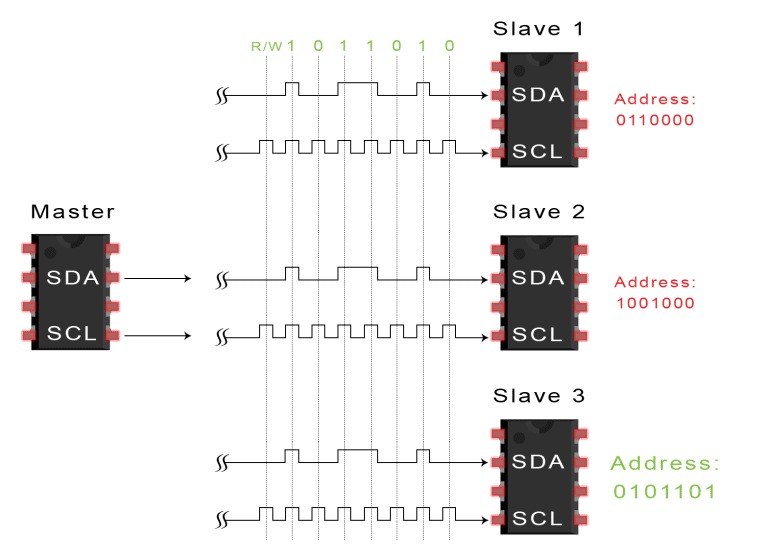
SINGLE MASTER WITH MULTIPLE SLAVES
Because I2C uses addressing, multiple slaves can be controlled from a single master. With a 7 bit address, 128 (27) unique address are available. Using 10 bit addresses is uncommon, but provides 1,024 (210) unique addresses. To connect multiple slaves to a single master, wire them like this, with 4.7K Ohm pull-up resistors connecting the SDA and SCL lines to Vcc:

ADVANTAGES
- Only uses two wires
- Supports multiple masters and multiple slaves
- ACK/NACK bit gives confirmation that each frame - is transferred successfully
- Hardware is less complicated than with UARTs
- Well known and widely used protocol
DISADVANTAGES
- Slower data transfer rate than SPI
2. Securing connection between boards using I2C.
To learn how to program the two controllers using I2C protocol it is important to understand the concept of a Master and Secondary board the “< Wire.h >” library, and how to open a communication between the two. For more information watch this video
For this assignment I have used my two boards designed during output and Input devices assignment week. Here I am using two RP2040 Microcontroller boards. I have deliberately chosen these boards because they are the ones I intend to use in my final project.
below you can observe the pinout for the SDA and SCL for better understand.

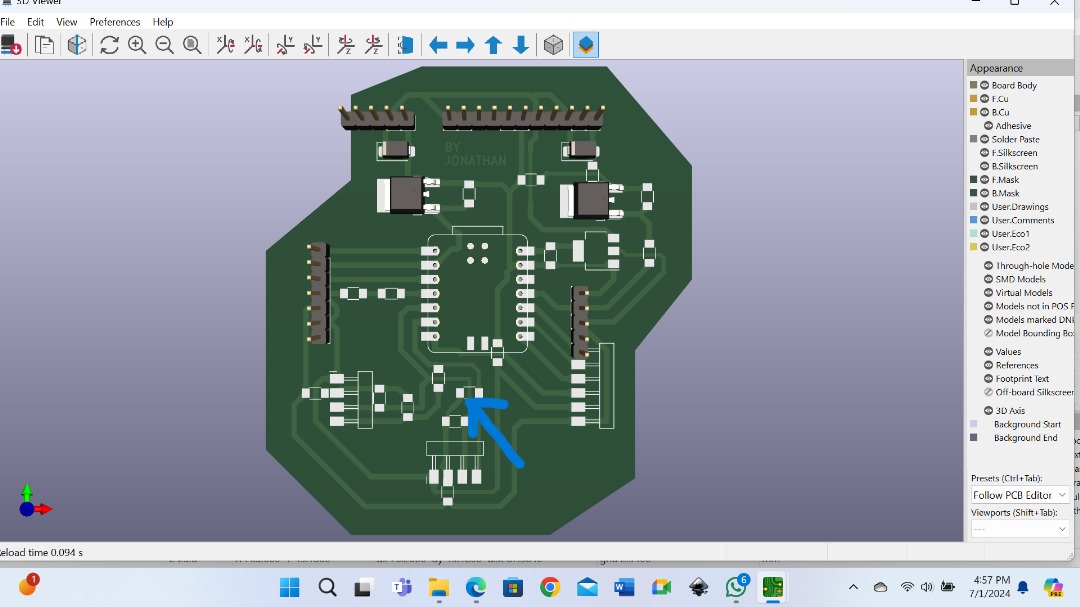
when I was designing my circuit I put into consideration the need of pull-up resistors as you can see from my PCB below.
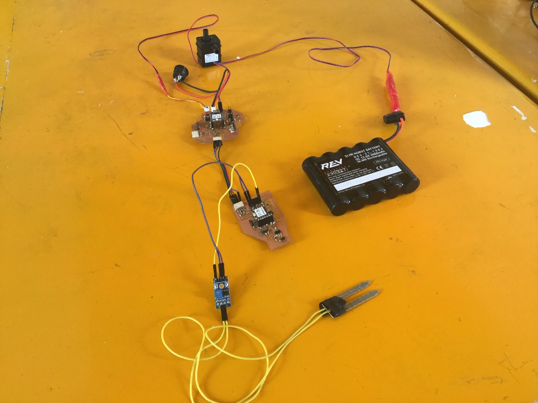
Since the assignment was to choose between wired or wireless network communication, I decided to do a wired network communication. Below you can see how I connected my boards. Actually, I used jumper wires for the connection.
3. Installing a program into the Master board.
To use the I2C protocol you need to call the Wire.h library and define the address of the secondary board (SECOND_ADDR ).
Again you need to initialize the Wire library using the Wire.begin() command in the void setup().
So, like we have discussed before, I am using two XIAO RP2040 microcontrollers boards, a Moisture sensor to read the moiture level, and the pump to pump water based on the moisture level.
Here’s how you can use I2C to communicate between two XIAO RP2040 boards, one as a master and the other as a slave, to read moisture sensor values and control the pump:
Master Board (RP2040)
- Connect the SCL pin to the slave board’s SCL pin
- Connect the SDA pin to the slave board’s SDA pin
Code:
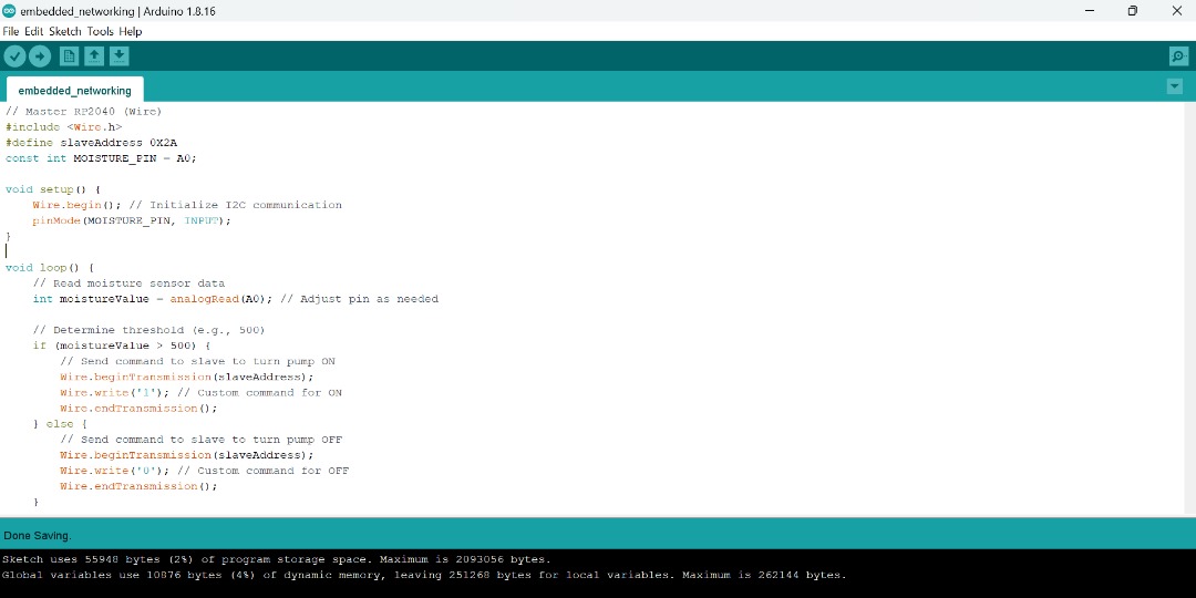
Master board.

#include <Wire.h>
#define slaveAddress 0X2A
const int MOISTURE_PIN = A0;

void setup() {
    Wire.begin(); // Initialize I2C communication
    pinMode(MOISTURE_PIN, INPUT);
}

void loop() {
    // Read moisture sensor data
    int moistureValue = analogRead(A0); // Adjust pin as needed

    // Determine threshold (e.g., 500)
    if (moistureValue > 500) {
        // Send command to slave to turn pump ON
        Wire.beginTransmission(slaveAddress);
        Wire.write('1'); // Custom command for ON
        Wire.endTransmission();
    } else {
        // Send command to slave to turn pump OFF
        Wire.beginTransmission(slaveAddress);
        Wire.write('0'); // Custom command for OFF
        Wire.endTransmission();
    }
Now we can proceed with the second board.
4. Installing a program into the second board.
On the secondary board you need to again include the Wire.h library and define the board’s address (SECOND_ADDR ). Again you want to initialize the communication but tell the microcontroller that it will be a secondary by adding the name of its address Wire.begin(SECOND_ADDR).
The thing that is different for programming a secondary board is you have to define a “receiveEvent” function and call it using the command Wire.onReceive(receiveEvent).
In the receiveEvent function you need to read the value from the command using the wire.read() command.
Below is the second board configuration.
Second Board (RP2040)
- Connect the SCL pin to the master board’s SCL pin
- Connect the SDA pin to the master board’s SDA pin
- Connect the moisture sensor to an analog input pin (e.g., A1)
Code:
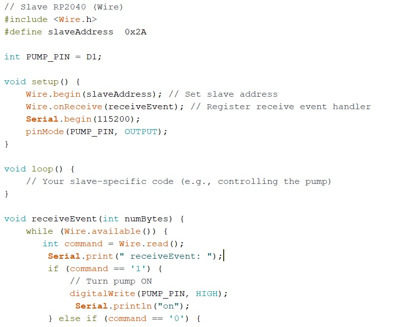
Second board.
#include <Wire.h>
#define slaveAddress 0x2A
int PUMP_PIN = D1;
void setup() {
Wire.begin(slaveAddress); // Set slave address
Wire.onReceive(receiveEvent); // Register receive event handler
Serial.begin(115200);
pinMode(PUMP_PIN, OUTPUT);
}
void loop() {
// Your slave-specific code (e.g., controlling the pump)
}
void receiveEvent(int numBytes) {
while (Wire.available()) {
int command = Wire.read();
Serial.print(" receiveEvent: ");
if (command == '1') {
// Turn pump ON
digitalWrite(PUMP_PIN, HIGH);
Serial.println("on");
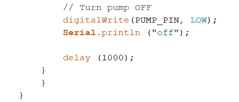
} else if (command == '0') {
// Turn pump OFF
digitalWrite(PUMP_PIN, LOW);
Serial.println ("off");
delay (1000);
}
}
}
Now we can run the program.
5. Run the program and observe if the communication has been established between the two boards through the I2C Bus.
In this code we expect the pump to turn ON and OFF depending on the moisture value. It can also show on the serial monitor whether the pump is ON or OFF. But on the video, I only captured the pump I did not bother to go to the serial monitor after the pump can show by itself.
Remember to adjust the pin numbers and I2C address according to your specific setup and requirements.
Below is the video showing the I2C connection and the result from the pump in response to the code.
6. Debug where necessary.
There was nothing much to debug. But some minor errors were found like loose connections which could lead to power failure in the board at some point. The possible solution was to simply solder it strongly.
What I have learned.
-
During this week I learned how to establish communication between microcontrollers. I had never done this before and I never thought I could do it either, but eventually I learned alot about communication and ways to achieved it and now I am happy that I did it.
-
I learned about UART, I2C, and other communications, each one working differently and the truth is that I personally find them very interesting and somehow complicated because you have to be patient and discover errors step by step. Very stressing but by the end of the day alot of learning is achieved.
-
I learned that the PINS and the datasheet of the microcontrollers are very important to know, especially when it comes to developing a communication between two of the same or different type of microcontrollers.
What to take into account.
-
From this week’s lesson I would recommend that you should take into account all the charateristics of the microcontrollers at the design stage of your development boards as this can eliminate some problems that might arise in future. This is so because sometimes we design unconsciously while the distribution of the PINS matters most.
-
It is important to take into account the communication protocol that we are going to use for the different projects that we can develop. It is very important to know the characteristics they offer us.
Files.
What went well/what went wrong.
This was a very busiest week for me. I have learned alot new staff the things that I long desired to know very interesting things. Stresses were there but alot of learning has been achieved.
What went wrong
My input board had a loose connection between the microcontroller ground PIN and the pad. This gave me a headache. It took me hours to Identify this problem and it dragged me down on finishing time.
How I solved this problem
So, by doing continuity test tirelessly on the whole circuit I ended up finding the fault which was a loose connection. So to fix it, I simply applied additional solder inorder to make the connection electrically sound.