5. Electronics production
A Hero shot.
GROUP ASSIGNMENT:
- Characterize the design rules for for your in-house PCB production process send a PCB out to a board house.
Here is a group assignment link
The group assignment link has been embedded on my page below.
INDIVIDUAL ASSIGNMENT:
This week we were individually assigned to;
-
Make and test a microcontroller development board.
-
Extra credit is to personalize the board and make it with another process.
We were instructed to visit Adrian Torres repository and download the gerber files that contained necessary information for the assignment.
Step 1. Generating G-Code using FlatCam:
So, to begin with, I download and install the Flat CAM software for generating Gcodes. Flat cam download here
Then I visited AdrianTorres repository to download the three files. To manage that, I first opened the fabacademy 2024 schedule and open the electronics production. On the individual assignment I clicked on microcontroller development board.


This took me to Adrian Torres repository.

I click on find file to open the files where I need to select my three files that will enable me to generate Gcodes for my assignment on flatcam.

Here I downloaded my three files that is edge cut file, trace tracks file, and hole drilling file.

Generating G-code
So, we’ll be using the “Flatcam” software to generate the G-code for our design, which will enable us to cut out our PCB board.
At the end of this operation, we’ll generate 3 gcodes.
A first gcode will create the holes on our board, a second will trace the tracks and a third will cut the shape of our PCB.
Gerber: Typically define copper layers in a circuit board.
Excellon: (drill file): Contain drill specifications, size, and coordinates.
G-Code: CNC machine instructions for cutting and/or drilling.
Data in FlatCAM is in the form of 4 different kinds of objects: Gerber, Excellon, Geometry and CNC Job.
Gerber, Excellon and CNC Job objects are directly created by reading files in Gerber, Excellon and G-Code formats.
Geometry objects are an intermediate step available to manipulate data.
So, after downloading the three files I open Flatcam.

Then I go to File > Open gerber.
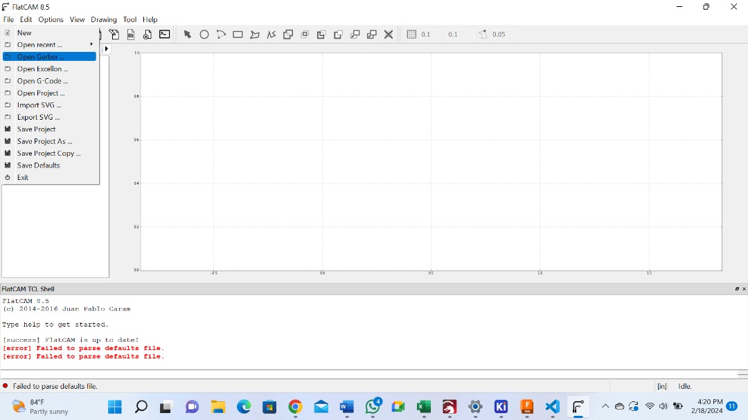
That took me to the files directory where I can select the gerber files for my project.

Then I need to set my file to be at zero. To do that I double click the file on project and scroll down to set offset values. The offset value I used is -120 and 80 respectively. This is because my file was displaced away by the opposite of those margins. I changed those parameters for three files in just the same order.

After aligning my file now, I open project and I double click to open the file and set other parameters.
Isolation Routing
- The folowing are the parameters I configured.
Tool diameter: 0.33 mm
Width (number of passe): 5 mm
Pass overlap: 0.3 mm
After inserting the values you click on create geometry.

You can observe the change of color to the circuit.
Then you create CNC Job
To create a CNC Job, you double click to open a new file that has emerged from Isolation Routing configuration we just did recently.
I used the folowing parameters.
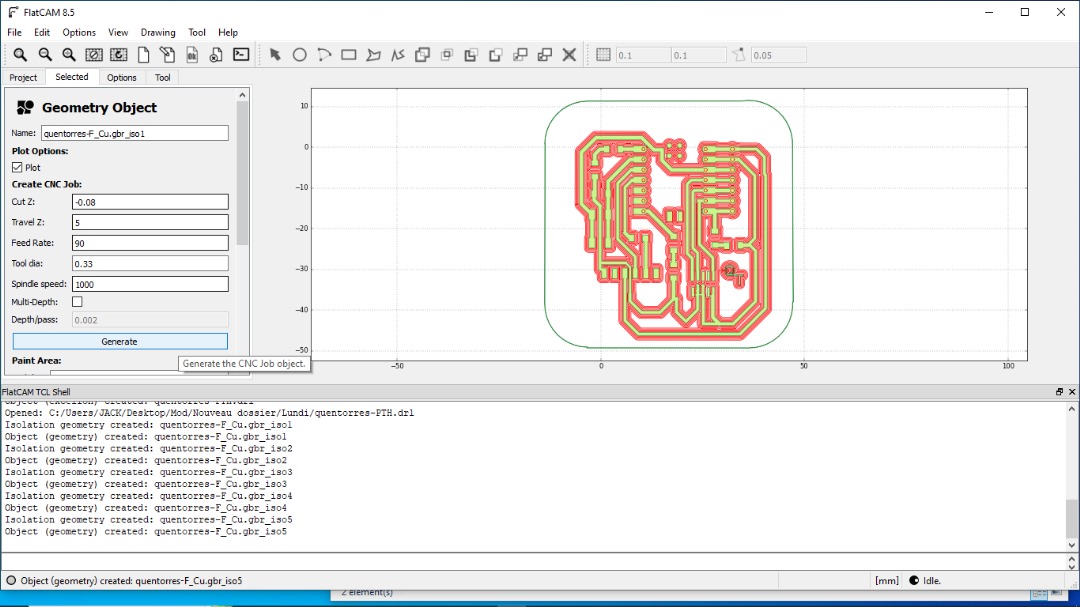
Create CNC Job
Cut Z: 0.08mm
Travel: 5mm
Feed rat: 90mm
Tool diameter: 0.3mm
Spindle speed: 1000 mm/min
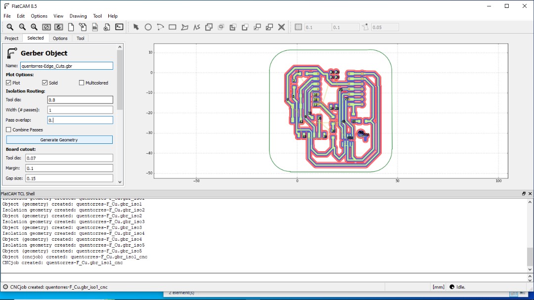
EDGE CUT
Isolation Routing:
I made the following configuration.
Tool diameter: 0.8mm
With(pass): 1
pass overlap: 0
Create CNC Job
Cut Z: 1.6 mm
Travel Z: 0.1 mm
Feed rate: 90mm/min
spindle speed: 1000 mm/min
Depth/pass: 0.4

PTH.drt (settings for Holes)
Again double click and set the parameters for Hole drilling.
Mill Holes
Tool diameter: 0.6 mm
Click generate

Again doble click on the new file to create CNC.

Create CNC Job (for PTH.drt)
Cut Z: 1.6 mm
Travel Z 5 mm
Feed rate: 90mm/min
Tool diameter: 0.6mm
Spindle Speed: 1000mm/min


Now we need to export the three G-codes we have generated for the files.
To export, double click on the G code and select export. Choose the folder to save your file. Repeat the process for all codes files.
Now it is the time to create our PCB.
Step 2. Machine conifiguration:
Loading files into software.
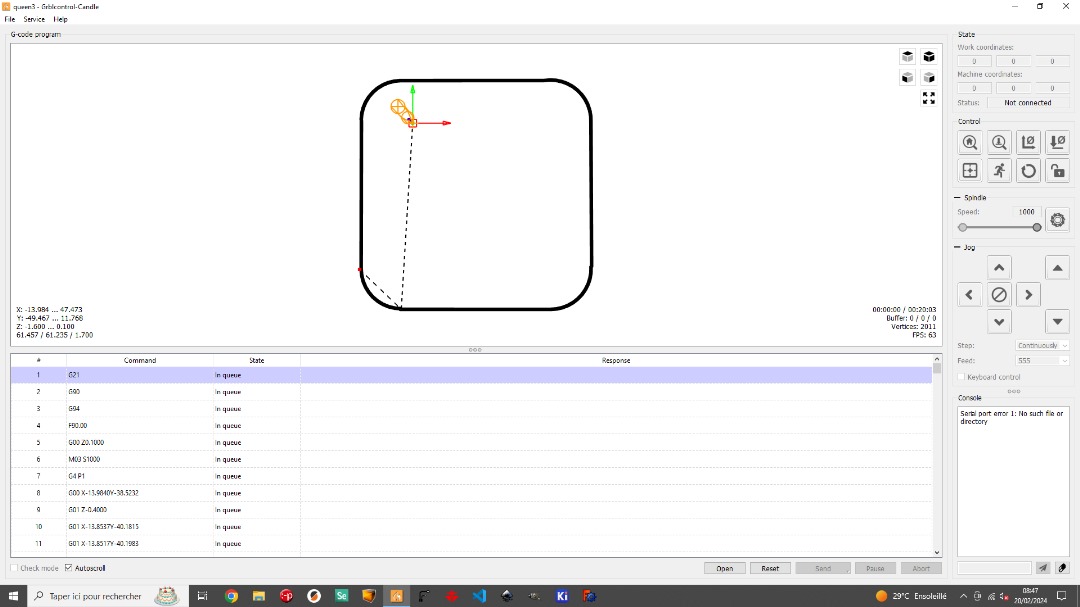
To control our machine, we use the Grblcontrol-Candle software, whose interface is shown below.
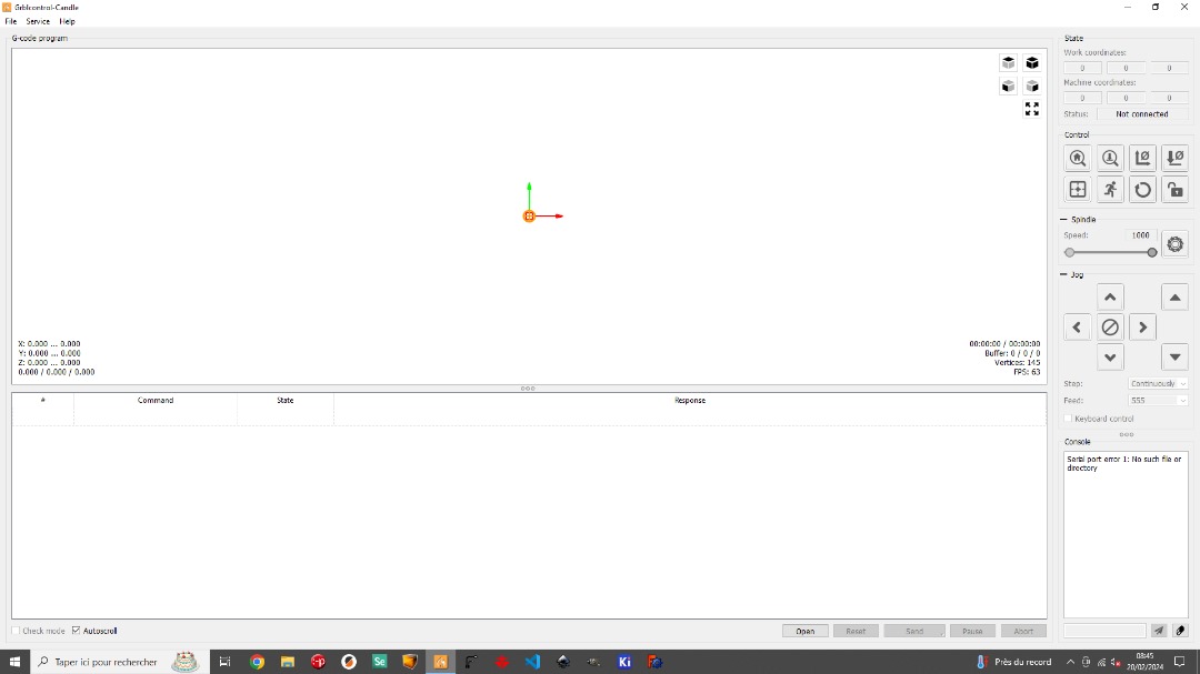
we connect our computer with the CNC machine.
Then, I transfer my G-Codes files to the computer that controls CNC machine.
Then I go to File> Open and choose file to open.
So, the first file I open is the G-code for Holes. This will enable me to create holes on my copper plate. But you can start with any file.

Then I adjust the working parameters of my CNC, that is the X- axis, the Y- axis and the Z- axis respectively.
Basically, X and Y are for the Bed and Z is for the steps.
Lastly, I zero the XY Coordinate and Z- Coordinate and click simulate to observe the cut before clicking send to initiate action.
The above process will be repeated for all other G-Codes.

That is for Edge cut.
Installing cutting material on machine and start CNC
First, we need to prepare the bed of our CNC to hold the copper plate to be cut. To do this, we use a double-sided skotch to hold the plate firmly on the bed.
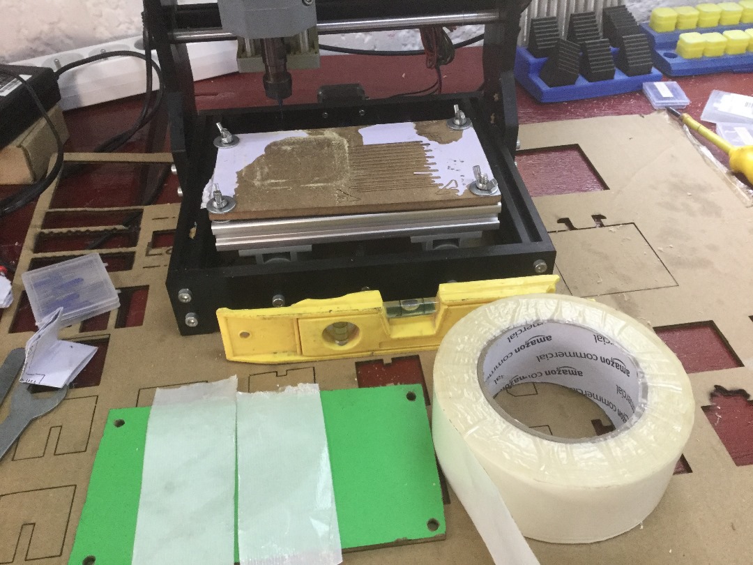
To start with, I level the Bed of my CNC machine.
This is very crucial to achieve preciseness of your cutting.
Then I change the Bit of my machine.
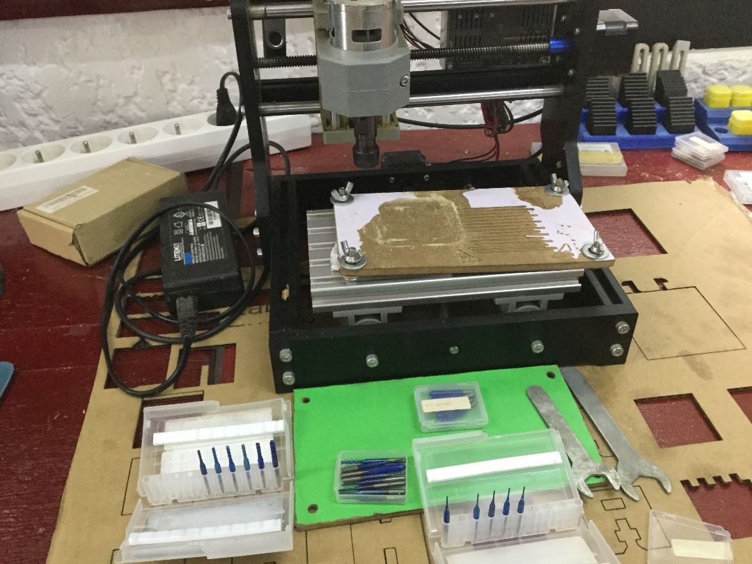
In my case I use V-bit for cutting tracks and End mills for Holes and Edge cutting.
Then I place my copper plate on the Bed and adjust it appropriately to ensure precise cut.

Now I am sure it is leveled.

Then I set the Origin using my axis parameters on the computer, while I try to squeez a piece of paper placed under the bit.
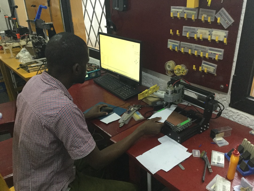
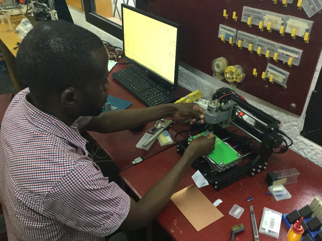
Now I launch the machine for cutting.
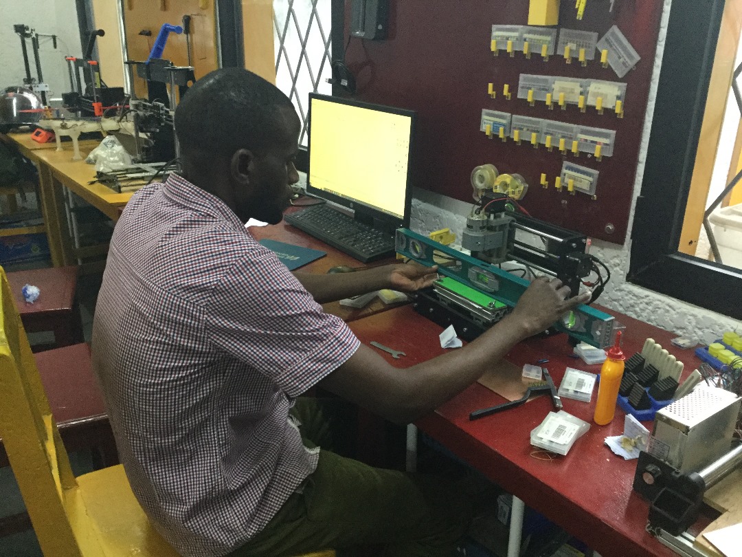
Below Photo is my Instructor observing closely how the CNC is performing. Everything was going just fine.

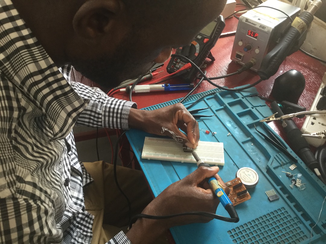
Step 3. Soldering, Testing, and program the Board.


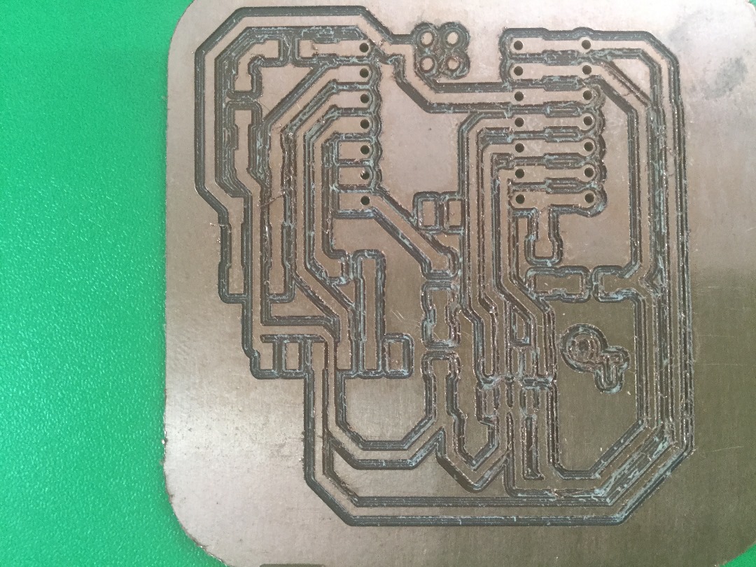
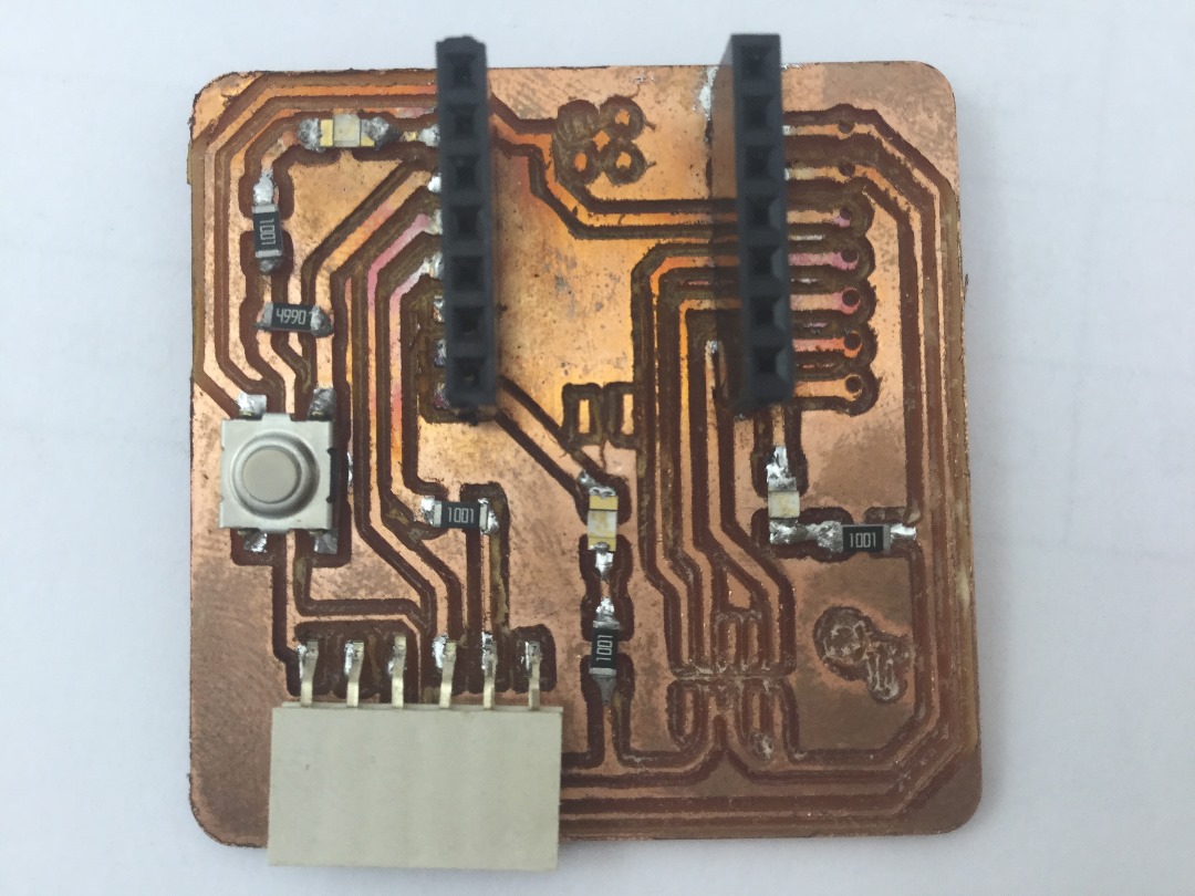
Now before soldering commence, let me test the continuity of my circuit.

Now it is time to put components together and test the circuit continuity and performance.


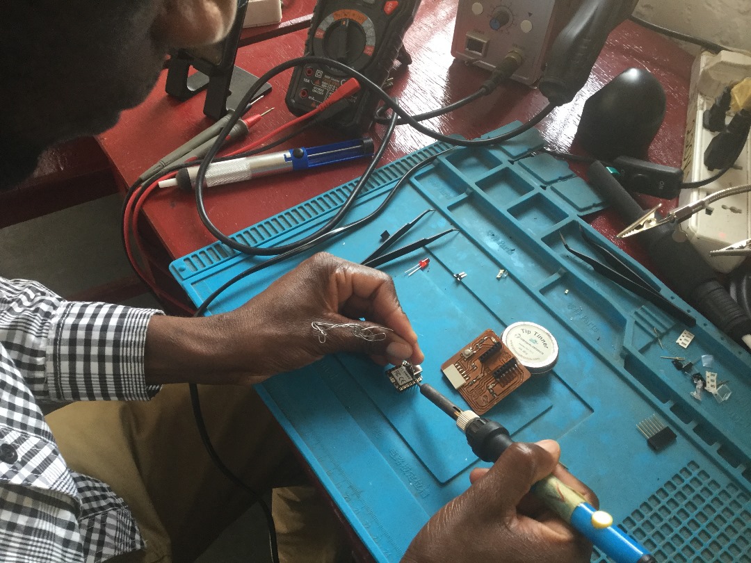
Hopefully I am close as you can see below.
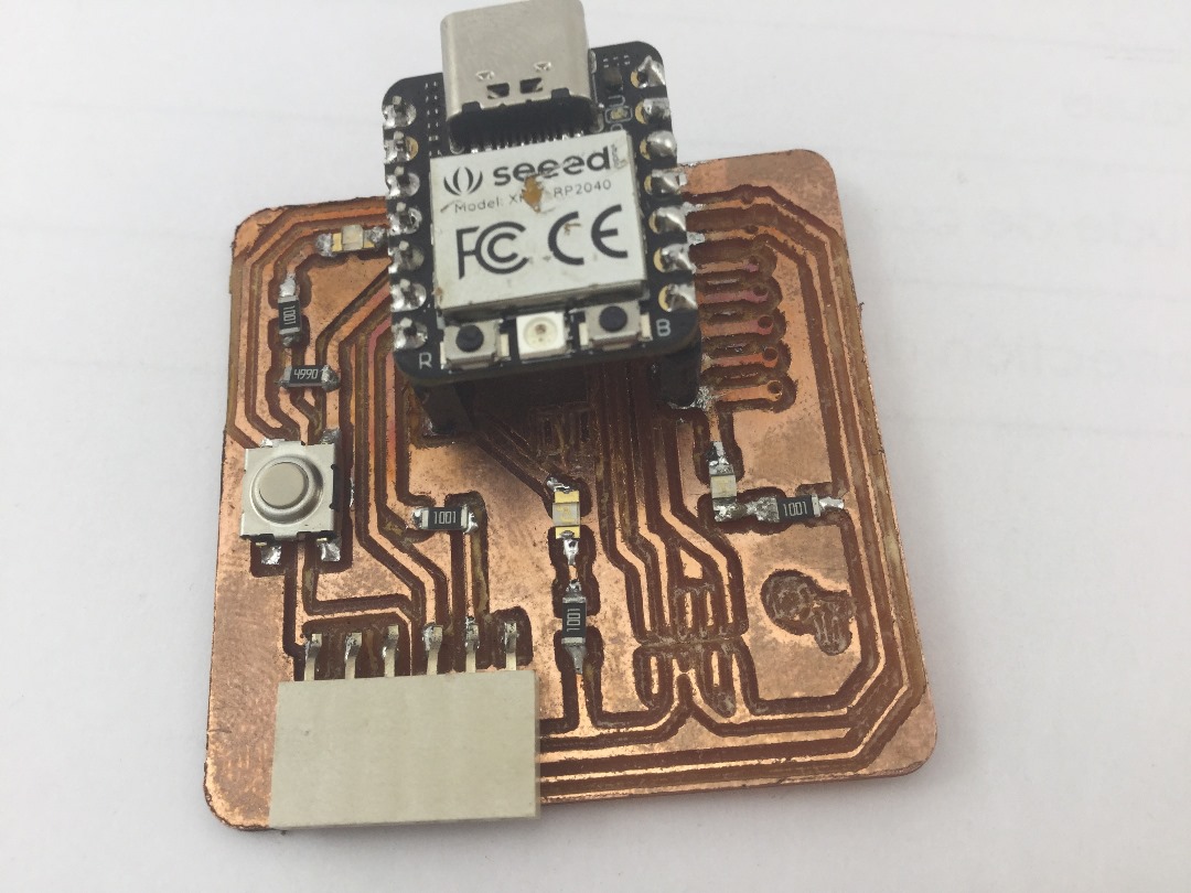
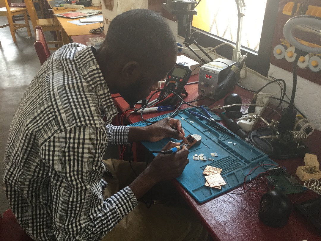
So far soldering is done as you can see.
Step 4: Open Arduino program.
Now I need to install a program in the Board to test its performance.
First, I need to download and install Arduino IDE software in my PC.
After installing Arduino IDE software my Seed XIAO RP2040 board is not found among the types of boards available.
I was instructed to visit Adrian repository again to copy the URL that contain different boards including my Seed XIAO RP2040 and install it in my Arduino.
Below are the procedures that I followed to make it happen.
I visted Adrian repository to find this Link.

Below arrow pointing on the URL that I copied.
Then I go back to my Arduino, click on File and select preferences.

Below arrow pointing on additional Board manager URLs space, where to paste the URL that I copied from Adrian repository.
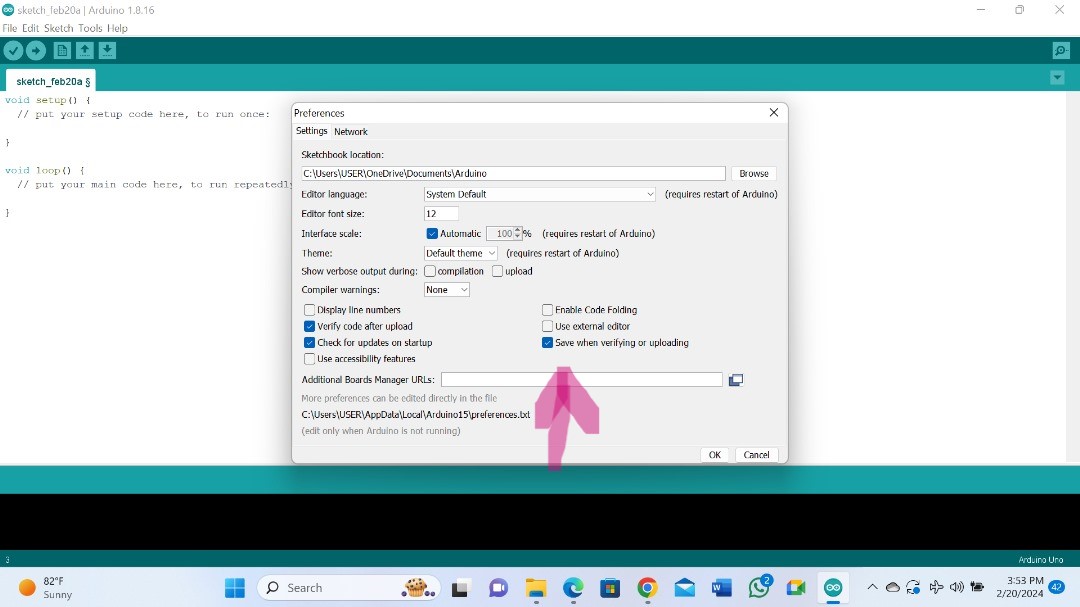
I click on that and open a space to add your URL.
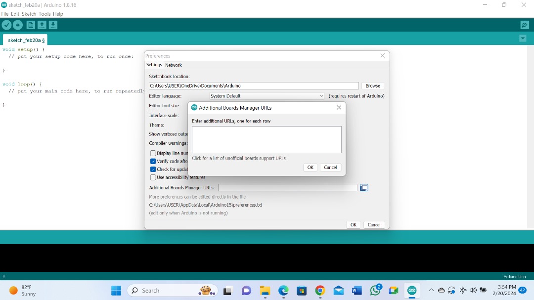
Below arrow pointing the URL that I have pasted.

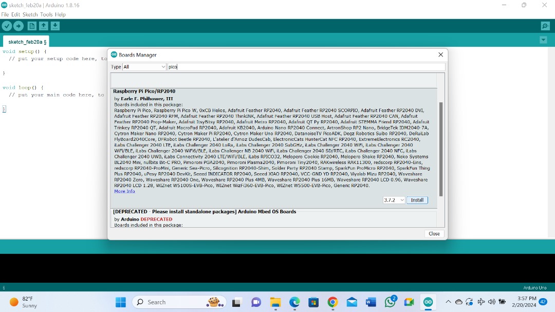
Step 5: Boards Manager.
Then I click on tools and select board manager to install my seed RP2040.

After opening, here you find different boards including Seed RP2040. Then I click install.
Step 6: configuring the Arduino IDE for the Seed Studio XIAO RP2040.
Now you can see my board is appearing among the the list of boards available.

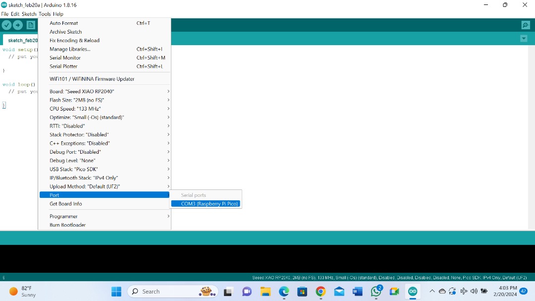
Then I go back to tools and check the port. it is registered in port COM 3.
Step 7: Load the Blink program.
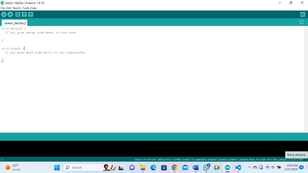
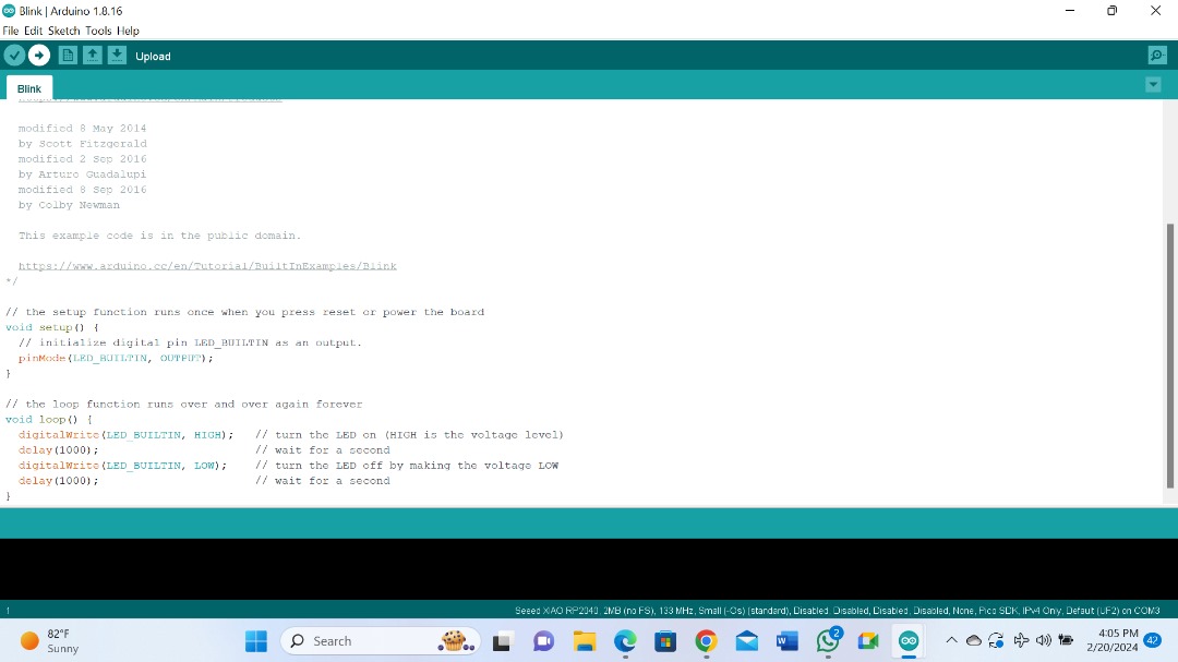
Now the last procedure is to install a program which is an example code which Blinks the built_in LED.
So, go back to File> example and choose basic blink program.

And here you can see an example code for LED blink.

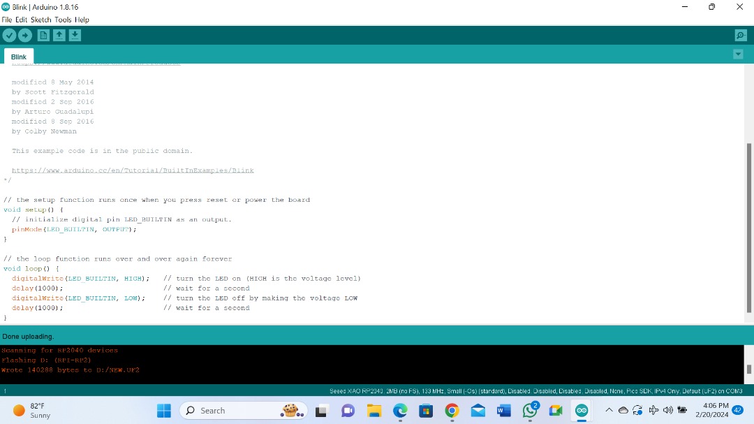
I clicked on verify and thereafter, upload. This is to install the program into my board.

Here uploading is done
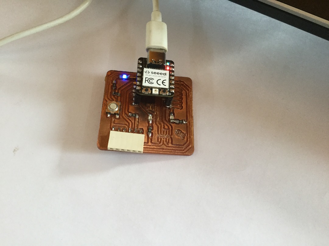
Now you can observe my Board is flashing on and off in response to the installed blink program.
Files.
What went well/what went wrong.
Generally everything went well. Since electronics is one of my hobbies, I found it a very interesting week. In-fact I have learnt amazing new skills.
What went wrong?
Unleveled bed
When the Machine started milling, I noticed that there was a problem with the bed. So, I had to abort the process. The Bed was not well leveled so the cut was good one end while on the other end, it was just scratching unable to go down like the other end.
How I solved it.
So, I had to start leveling process again to level the bed using a Spirit Level and thereafter, align my PCB, tightened it and set my origin again and send.
Now everything went well.