10. Output Devices
Hero shot.
Assignment Overview
group assignment
- Measure the power consumption of an output device.
Individual Assignment.
- Add an output device to a microcontroller board you’ve designed, and program it to do something.
Group Assignment
Here is a group assignment link
The group assignment link is also embedded below.

As per assignment requirement to measure the power consuption of the output device, I decided to measure the the power consumption of the Fan.
Since power is the product of voltage and current (V*I), I measured the current output of the Fan and Voltage output from the source then multiply the two figures.
To measure the current output, set your measuring instrument on ammeter (A),connect the measuring instrument in series with the load which is the Fan.Here you need to disconnect one cable the negative going to the Fan and connect the multimeter in series. Measure and record the result.
Then to measure the voltage output, set your measuring instrument in my case a multimeter KAIWEETS HT118A to (V) Voltimeter, and connect it in parallel with the load i.e positive probe to positive terminal and Negative probe to negative terminal. Measure voltage and record the results.
And finally, multiply the two results to get total power consuption of the load Fan.
Individual Assignment
Designing
For this individual assignment, I need to add an output device to my Microcontroller board that was produced in the previous week during electronics design assignment.
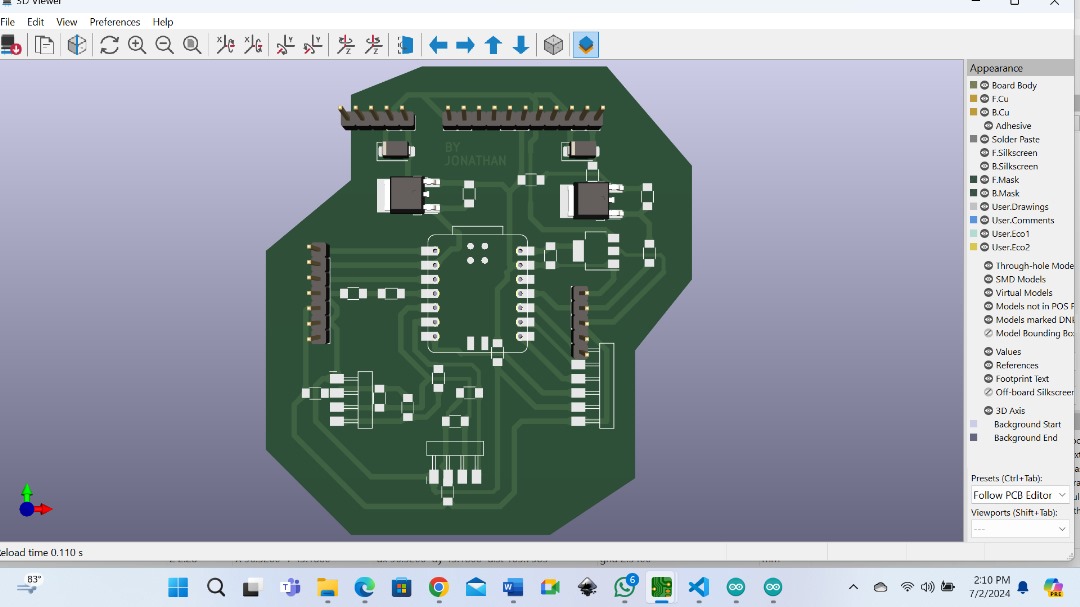
Below is the the Microcontroller board that I am going to use.
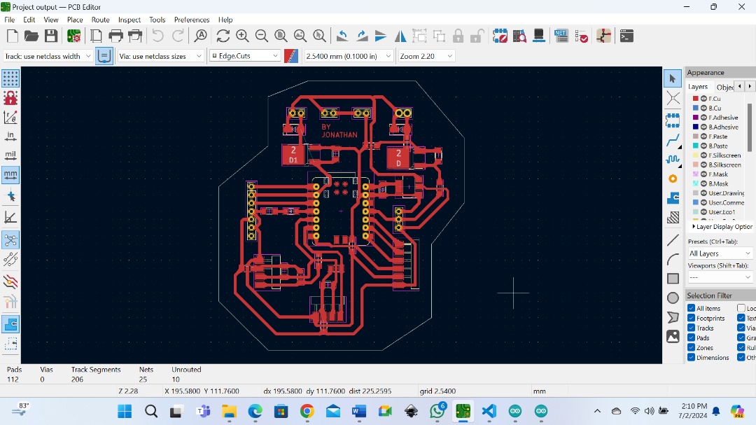
So, my Microcontroller board was already designed to accommodate other output devices like fan and water pump to outfit my final project.

I decided to add and try to control a fan as an output device to my Microcontroller board.
Programming
On my board, I am using XIAO RP2040 Microcontrol to control the fan.
The following is the code that I used to program the fan.

But first I connect the Microcontroller and test it on the breadboard. And below you can se how it is working. I programmed it to run for a second and delay for 10 seconds.
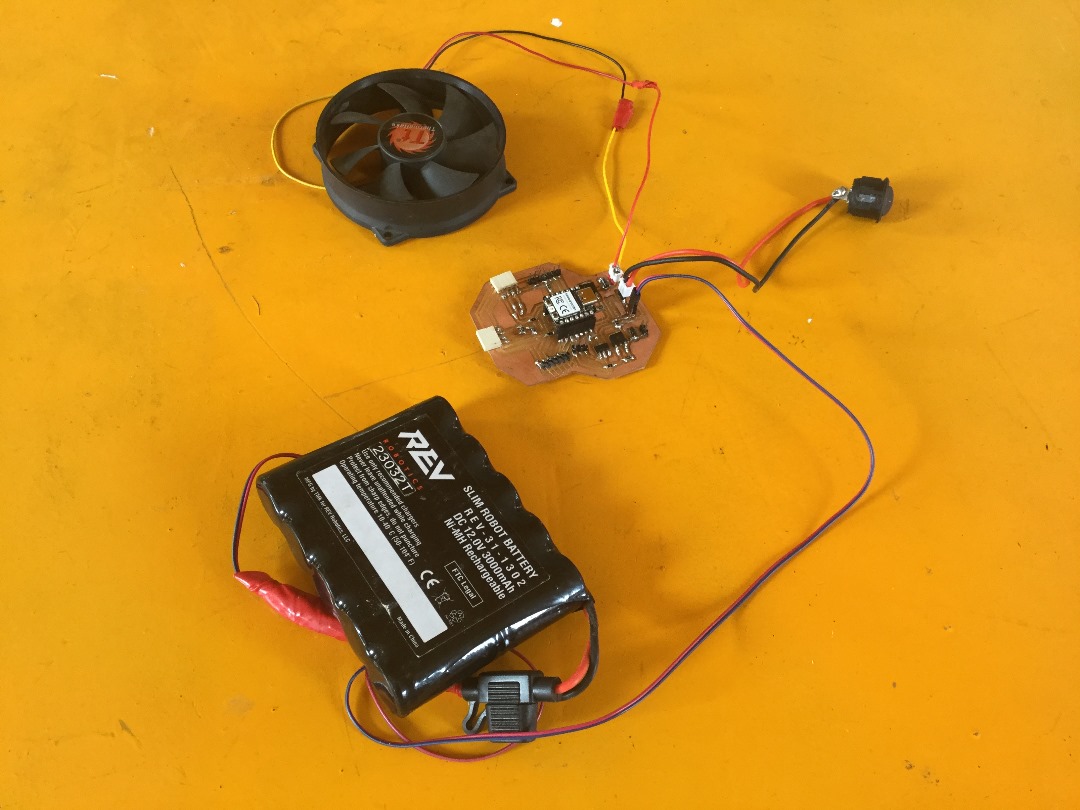
After being successful on the breadboard now finally, I connect my board as you can see below .
Files
What went well/what went wrong
What went well
This was abit an easy week for me since I already designed my Microcontroler in such way that it can accomodate output devices. But generally, was another interesting week.
What went wrong
I had a problem at first as the Fan was running continuously non-stop, totally differing with the program. The program was to make it run 1 second and delay 10 seconds. This was so because the ground from the Microcontroller was did join with the gound from the source/ power supply.
To fix that I made a jumper wire between two points and all was solved.