11. Mechanical design, Machine design.
Hero shot
Assignment Overview
Group Assignment:
-
Design a machine that includes mechanism+actuation+automation+application.
-
Build the mechanical parts and operate it manually.
-
Document the group project and your individual contribution.
Here is a group assignment link
The group assigment link is also embedded below.
Individual Assignment:
- Document your personal contribution on the project.
As per requirement, we were tasked to document our individual contribution on the project.
Electronics and Programming:
My contribution part was in electronics to find and install software programs to run our motors and hence running our machine respectively.
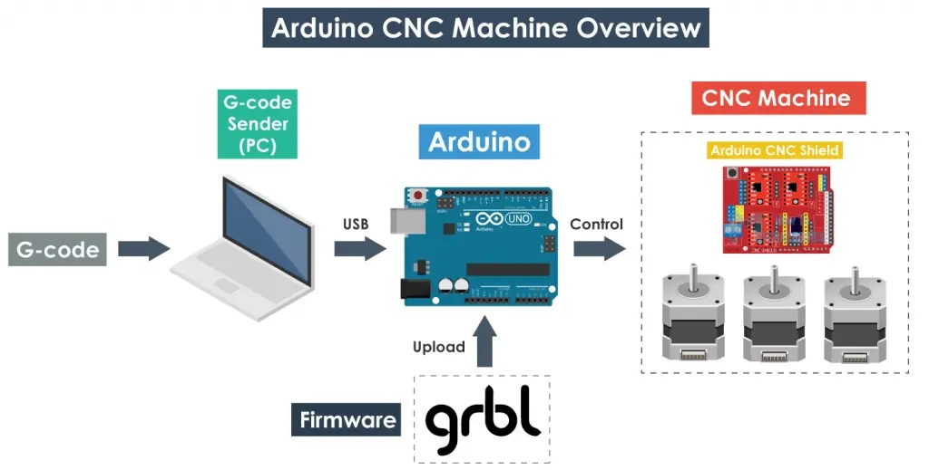
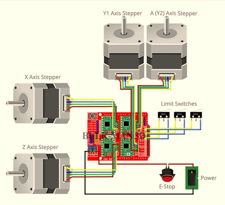
In this project, we will need Arduino board in this case we are using UNO R3, CNC Shield, and Nema 17 stepper motors as you can see below.

Below is a wiring diagram.
To accomplish my activity there are a number of steps we will go through.
Step 1: Install Arduino IDE.
So, to begin with you need to install Arduino IDE since we are going to use Arduino UNO R3. In my case I already have from previous assignments.
Step 2: Install grbl Arduino Library.
GRBL is an open source firmware which enables motion control of CNC Machines.
It’s a Firmware that we neeed to install or upload to the Arduino so it can control the Stepper motors of the CNC Machines.
In another words, the function of GRBL Firmware is to translate the G-code into Motor movement.
Download GBRL as a .zip file from here
After dowloading, follow these steps.
-
Open grbl-master.zip file and extract all files.
-
Open the Arduino IDE, and Navigate to Sketch> Include library> Add.Zip Library.
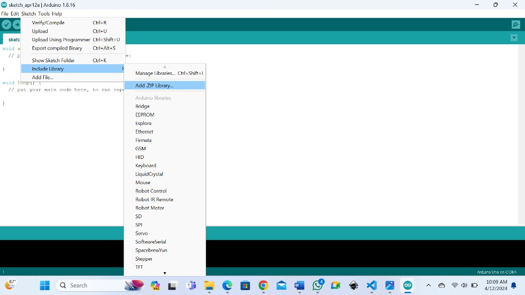
- Navigate to the extracted folder, grbl-master, in there select grbl folder and click open file. Now we have GRBL as an Arduino Library.
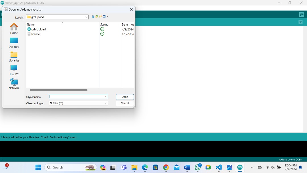
Then navigate to file > Examples > gbrl > grblUpload. A new Sketch will open and we need to Upload it to the Arduino board.

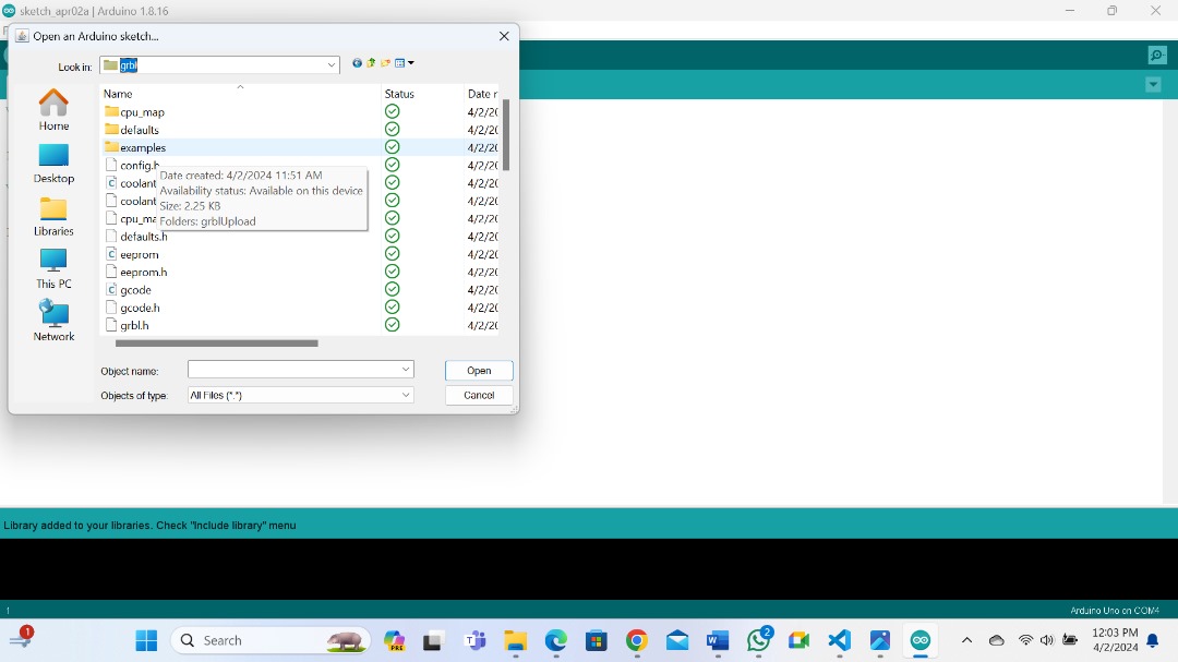
You need to click on grblUpload and select open.
Then this is what you need to Upload.
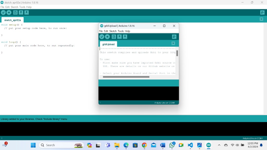
So, we just have to select the Arduino board, the COM port and hit the Upload button and we are done.
GRBL Configuration
At this point we should configure GRBL to our Machine.
To do that, open serial monitor and you can see the message like GRBL 1.1h or 0.9h [‘$’ for help].
If you can type $$ and press enter, you will get a list of current commands. below is how they look like.
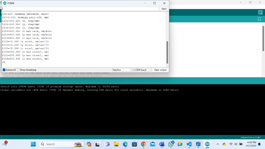
All those commands can be adjusted according to you CNC Machine.
Step 3: Install Universal G-code Sender (UGS).
So, once we have installed GRBL firmware, now our Arduino knows how to read G-code and how to control our CNC Machine accordingly.
However, in order to send the G-code to the Arduino we need another Software which will tell the Arduiono what to do. And one of the Software is the Universal G-Code Sender (UGS).
SO, download UGS from here
Once you download, we need to Extract the Zip file, then look for the folder named bin and open it. You will find two executable files 32 bit and 64 bit choose according to your PC and open.
This is actually a JAVA program. So, in order to run this you need to install JAVA Runtime Environment from here
Once we open this is how it looks like.
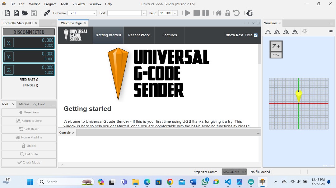
Now we can configure the machine using Setup Wizard which is more convienient than manually typing commands as we did before in the Arduino IDE serial monitor.

The first step here is to select boudrate which should be 115200, and the port to which the Arduino is connected. Once we connect the Universal G-code Sender with Arduino, in the next step we can check the direction of moving of the Motors.
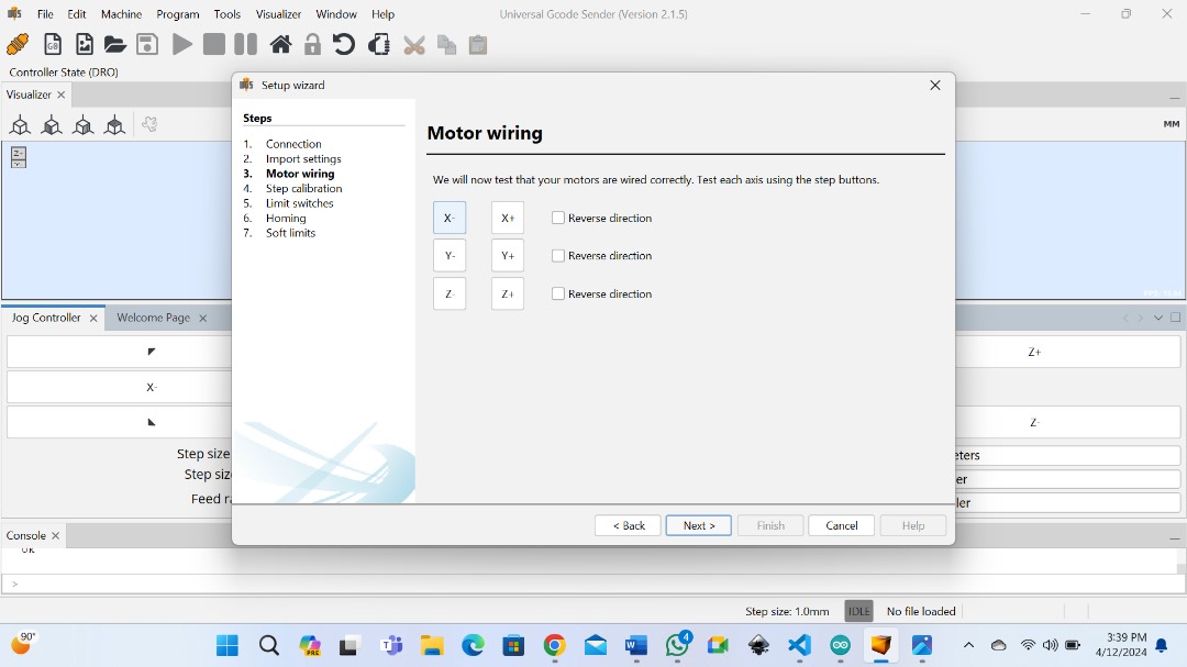
We can reverse the direction through the Wizard or by manually flipping the connection of the Motor on the Arduino Cnc shield.
Step Calibration
In the next step we can adjust the steps/mm parameters. Here the Setup Wizard will calculate and tell us to what value we should update the parameter.

The default value is 250/mm.This means if we click the move ” x+ ” button, the Motor will make 250 steps. Now depending on the number of physical steps the motor has, the selected stepping resolution, and transimission type, the machine will move some distance. Using the ruler we can measure the actual movement the machine made and enter the value in the Actual movement field. Based on this info the Wizard will calculate and tell us to what value we should change the steps/mm parameter.
In the UGS console, you can observe changes adapting to each command you execute.
Limit Switches
Limit Switches prevent the machine from moving beyond its physical limits.
In the next step we can enable Limit Switches to test if they work properly.

Depending whether normally open or Normally closed we can invert them here.
It is worth noting that we can disable the Z-Axis Limit switche. So, to do that, we need to edit the config.h file which is located in the Arduino Library folder (or documents\Arduino\libraries).

Homing
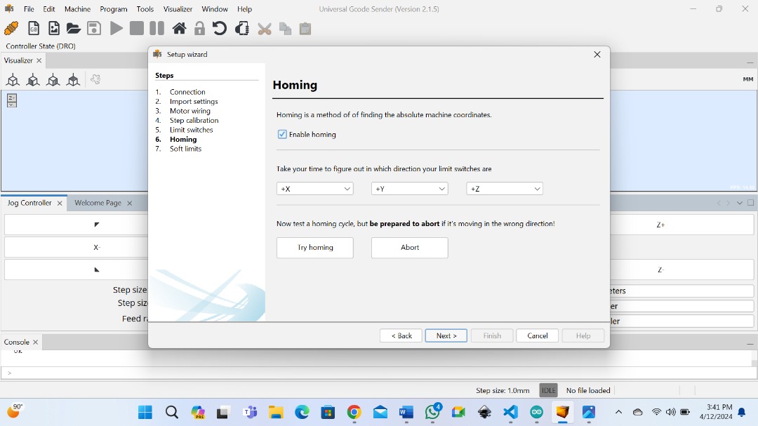
Using try homing button the machine will start moving towards Limit end Switches. Incase it goes opposite way we can easily invert the direction.
Soft Limist
Soft limits will prevent the machine to move beyond its safe work area.
We can also enable soft Limits in UGS Setup Wizard.
Step 4: Generating G-Code.
We can generate G-code by using Inkscape.
Using Inkscape Extension
Download Inkscape from here.
Now to turn any design in Inkscape into a Gcode our Plotter can execute we need to install a special extension called Gcode plot.
GCode Plot
you can download Gcode plot from here
So, dowload a Zip file in github and extract all.
Then go in your hard drive where your operating system is installed and open program files folder. In program files folder, navigate to Inkscape > share > Extensions. Copy all your files in the Gcode plotter you extracted in this inkscape extension folder.
Now we are ready to use Inkscape to create G-code for our plotter.
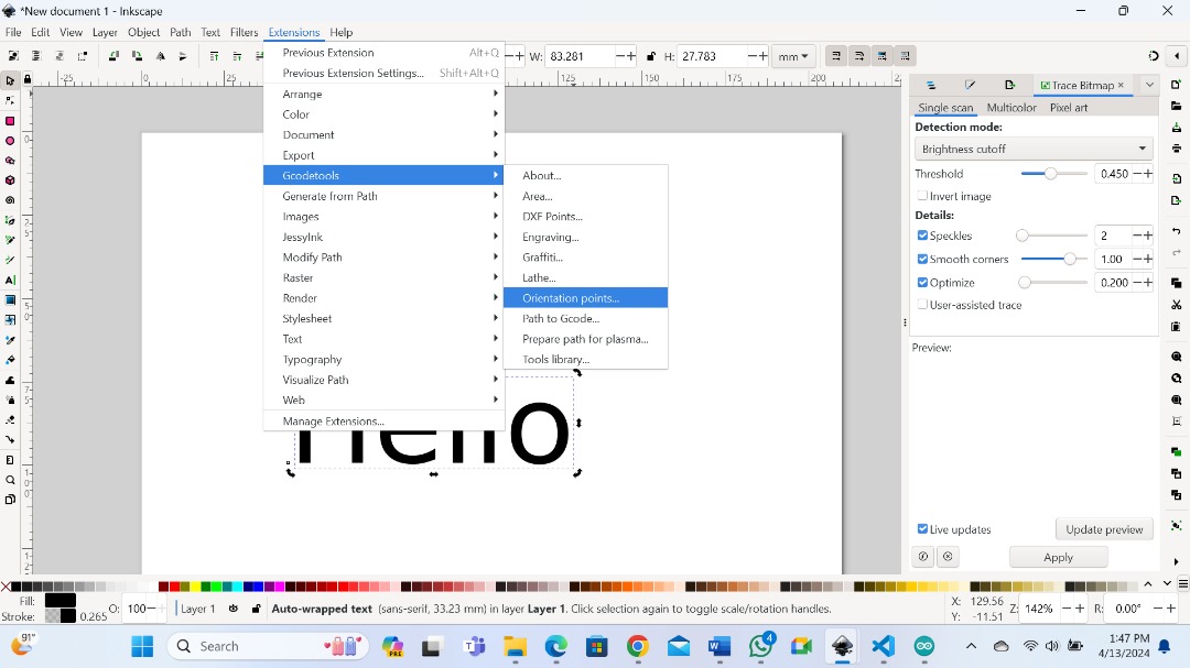
Go ahead open inkscape and draw whatever we want as you can see below. Make sure everything is converted to path.

Then go to extension > Gcode tools > orientation points.
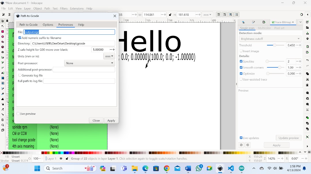
Then again extensions > Gcode tools > path to Gcode.
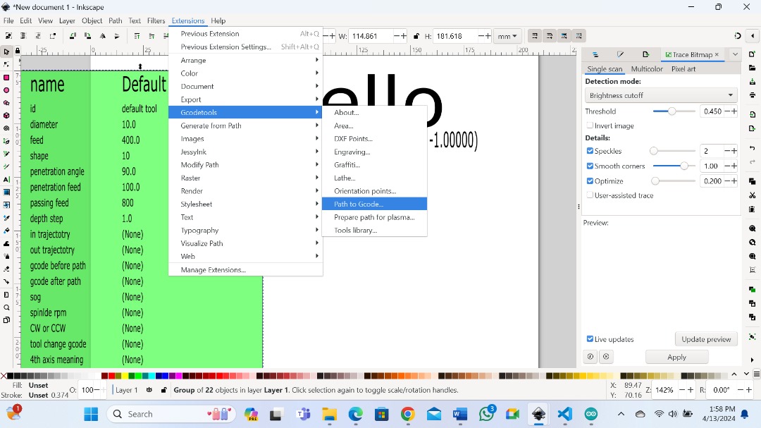
And here you set your output directory on preferences and thats it you have generated your G-code.
Files.
What went well/what went wrong
This was very exciting week and we have learnt alot. I did not expect that I can build a machine but it has happen. I am very thrilled with the skills I got and I am going to improve myself as time goes.
What went wrong
As usual when you are learning new staff there is alot of hikups along the way.
After connecting A-Y Axis on the CNC Shield I found out that there was a difference in steps between A and Y whereas the two are suppose to sychronise A is suppose to copy Y step. this took me time to figure out until I get advice from Paul to simly put connectors under the pins of the controller.
Another problem was on the Inkscape to generate G-code. I could not figure out the output directory. Likewise here Paul advised me to create a folder, open it and copy the URL and paste it in the preference where there is output directory in Inkscape.