CNC cutting, MCU development board making and testing
Write something at the front
- This week we will learn about electronics.
- We will have Quentorres PCB example for us getting started with tutorial.
- I will mill, solder, stuff once the PCB board once the board been came out.
Finally finishing this on 5.15th. There are few steps I am missing and not doing well since last time. Hence I will add the additional and the right ones.
Doing this at 4.13th and finish on 4.14th. It is what they always said: it will be really hard once you not balance the normal pace of study and work.
Understand the knowledge about the CNC machine
From the Neil's class, I understand there are different types of tools for the machine and we can have the different output. In the Chaihuo Fab Lab, this is the CNC machine we are using:
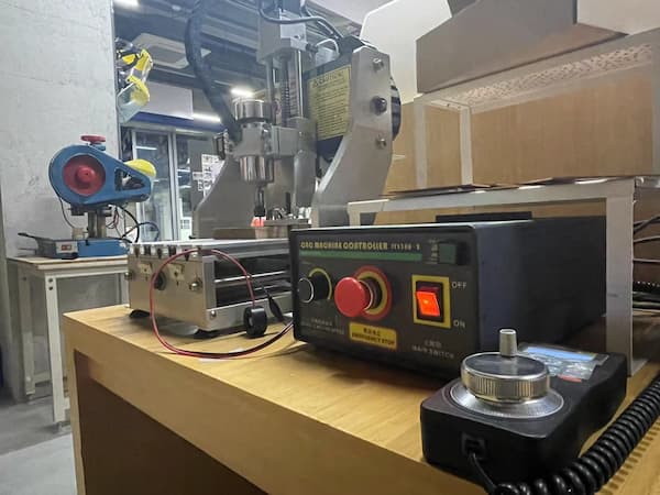
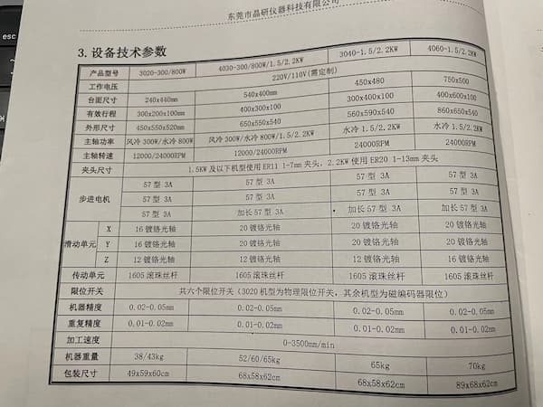
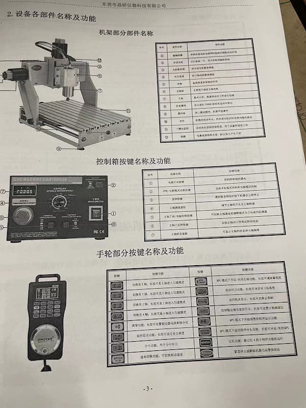
It is made by JingYan Instruments Technology and here is the each function of the mahcine and the detailed specification:
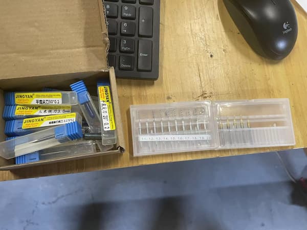
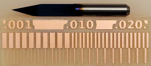
And there are differnt types of tools as well, including 1/64, 1/32 and V-bits that are mentioned in the class:
I got the wrong mill before.
The V-bit example from the class exhibition looks really good and I decided using this type of tool.
How does whole thing work
It requires "G-code" to make the CNC machine work. And there are multiple ways to generate G-code.
G-code is a language that is used to control CNC machines. It provides the necessary instructions for these machines to perform tasks such as cutting, drilling, or engraving materials. The language includes commands that dictate the movement of the machine along its axes, control the speed of the movements, manage the tool operations, and other specific actions required to shape the material according to precise specifications.
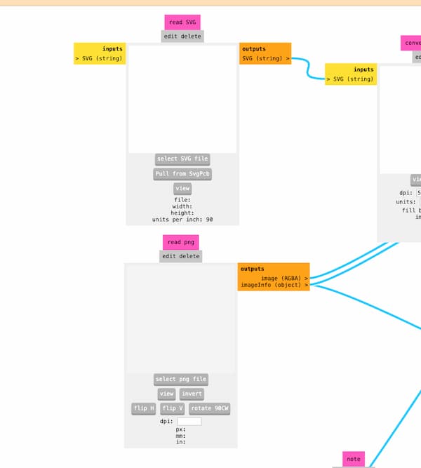
- Option 1: Directly using "Mods CE" tool to generate the G-code, it requires PNG or SVG images since they are lossless resolution.
- Option 2: Uploading the Gerber files to the related software of the CNC machine and let it generate the code.
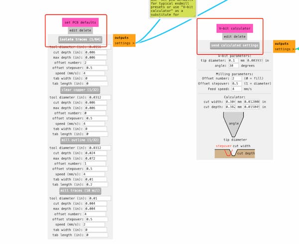
For both options, they all require the configuration of the parameters, which mean I need to know and need to:
- How thick is the board so that I can set the depth of the cut
- Set different parameters for different tools(1/64 end mill, 1/32 end mill, V-bit, etc)
- Set a reasonable width to keep the connection simple without cutting it
- Set the original point(zeroing)
For the safety and the lifetime of the machine and the tools, there are something that need to be awared:
- There should be a backing plate under the cutting board, which is generally wood
- The base and the board to be cut should be secured
- Determine the position at the beginning, ensure the origin, do not click "return to the origin" until you have a clear orientation
These are the preparations for cutting.
Get the PCB example file and understand the required components
First I need to get the example files from the GitLab:
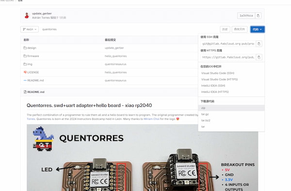
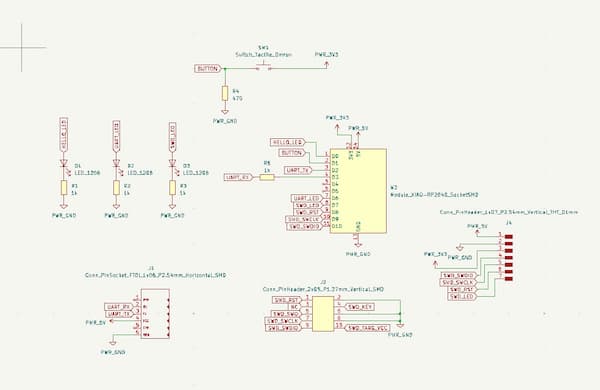
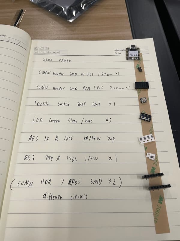
From the Quentorres. swd+uart adapter+hello board - xiao rp2040 I understood that the components should be inlcuding as below:
| Component | Quantity |
|---|---|
| SEEED STUDIO XIAO RP2040 | 1 |
| CONN HEADER SMD 10POS 1.27MM | 1 |
| CONN HEADER SMD R/A 6POS 2.54MM | 1 |
| Tactile Switch SPST-NO Top Actuated Surface Mount | 1 |
| LED BLUE CLEAR 1206 SMD | 3 |
| RES 1K OHM 1% 1/4W 1206 | 4 |
| RES 499 OHM 1% 1/4W 1206 | 1 |
| CONN HDR 7POS 0.1 TIN SMD | 2 |
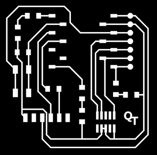
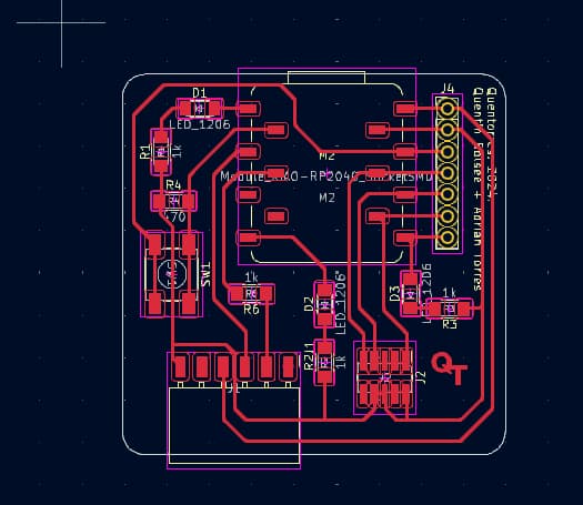
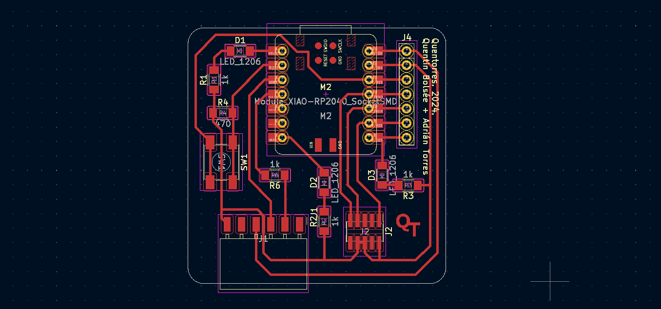
There are three types of the PCB board design: the front, the drill, and the edge. I select Version Two board as the learning version:
(Option 1)For generating the G-code with PNG or SVG image, the files contain them:
- This is for the trace, which is the front of the board, the main body:
- This is for the drill, which should be drilled through the board:

- This is the edge, which should be cut deeper to make sure the board can be cut out:

These images can be converted and calculated as G-code files, by Modes CE
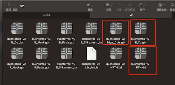
(Option 2)For generating the G-code with Gerber files, the required files are shown below, which represented as the front, the drill, and the edge.
There are Kicad examples for learning Kicad, which is already packed:
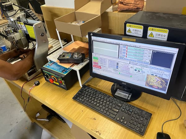
Use the CNC machine to cut the board
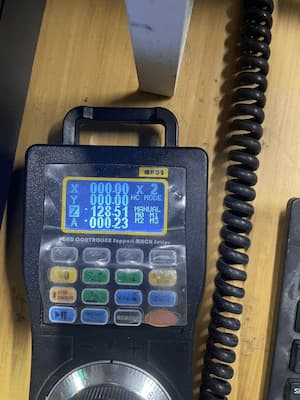
This is the machine we are using and it can be controlled by the computer and a wired remote control:
Ensure the board is been secured:
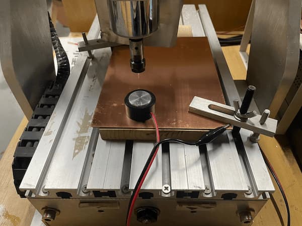
This tool is to make sure the machine zeroing right
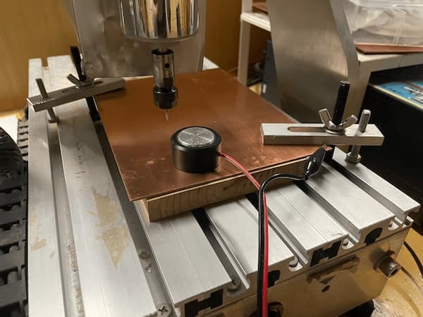
The preparation is done.
Cut the board with G-code from the Mods CE
Go the the Mods CE and there are two choise for the generating.
And there are different types of parameters selecting here:
After uploading the PNG image to it and set the parameters, and click the "calculate" which is on the final of the path. The whole trace is looking like:
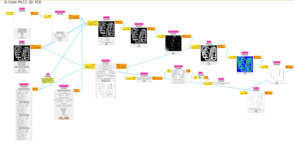
It will automatically output a G-code file and this is the cutting tracing looked like:
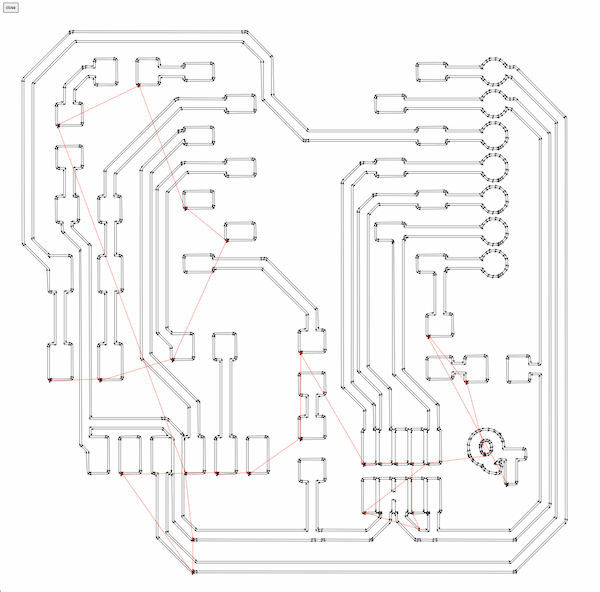
After uploading the rest two, I can upload the ".nc" files to the CNC machine and the files are looking like this:
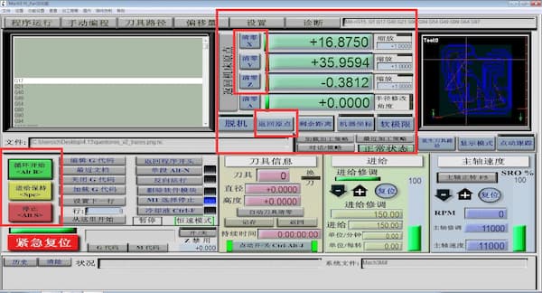
There are some parameters on the software:
- The position of the cutting tools
- The reset posotion button
- Start, hold, stop buttons
After clicking "Start" button, the machine will begin the cutting:
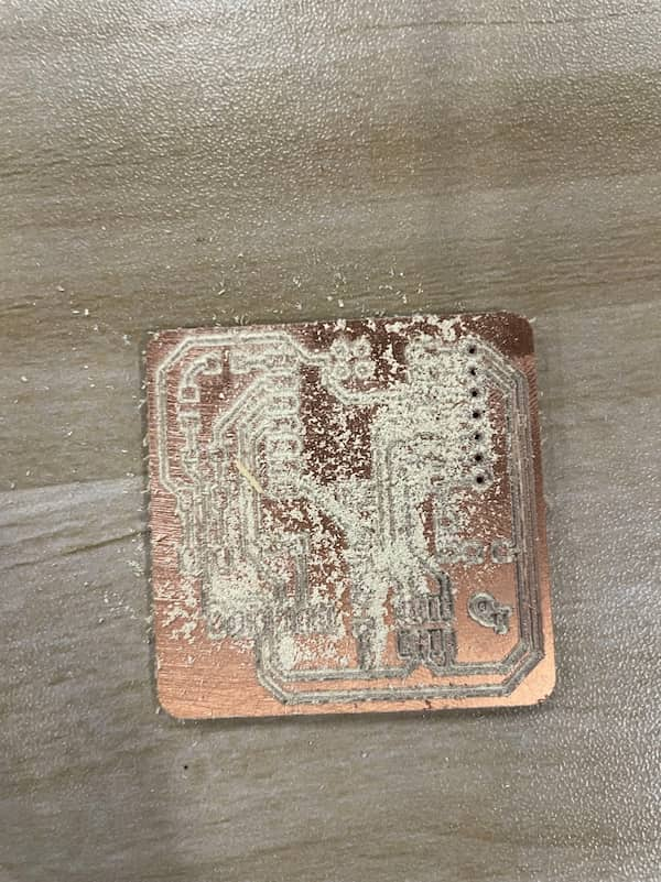
The board is not cutting very well as you can see there is a line of the cutting, because I click the "Reset" button and didn't focuse on the position of the V-bit tool.
Thus it can be took as a test, and later I am able to have the completed one:
(Not quite complete)
Updated on 5.15th
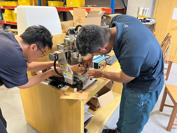
During these days, our tutor, Salman is coming to ChaiHuo and starting to help us with the assignments.

For the last time not quite complete board, I can improve it now.
At the very beginning:
The cardboard will always have one corner cocked up, so we used double-sided tape in addition to the retainer.
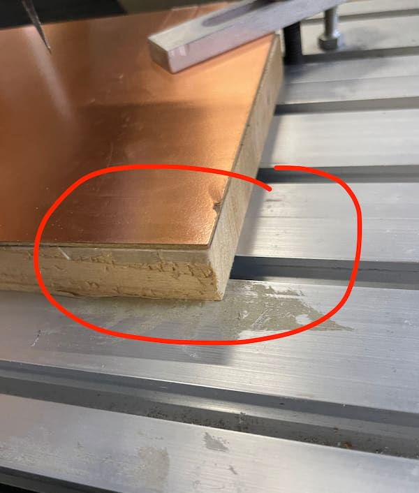
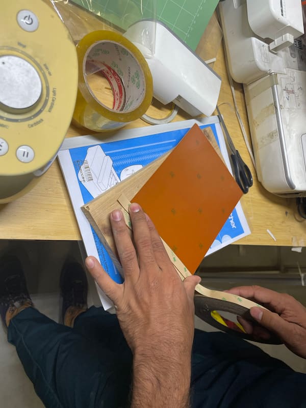
Then we we re-fixed it.
I did the ".png to .nc" file, the G-code file, before.
It is the time to prepare the end mills:
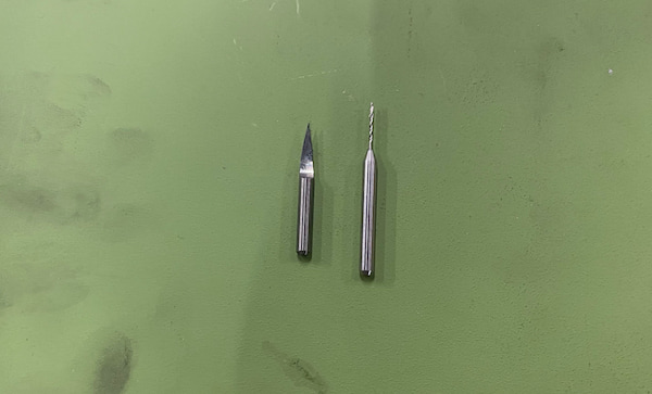
The left one is 0.4mm V-bit and right one is 0.8mm drill.
And we have three files:
- Traces-PNG.nc is using 0.4mm V-bit.
- Drills-PNG.nc and interior-PNG.nc are using 0.8mm drill.
After uploading the rest two, I can upload the ".nc" files to the CNC machine and the files are looking like this:
There are some parameters on the software:
- The position of the cutting tools
- The reset posotion button
- Start, hold, stop buttons
After clicking "Start" button, the machine will begin the cutting and drilling:
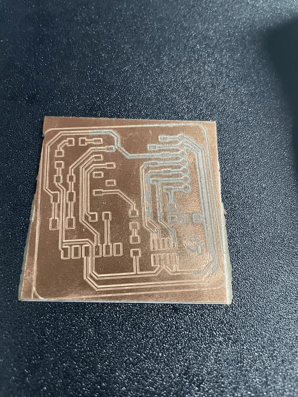
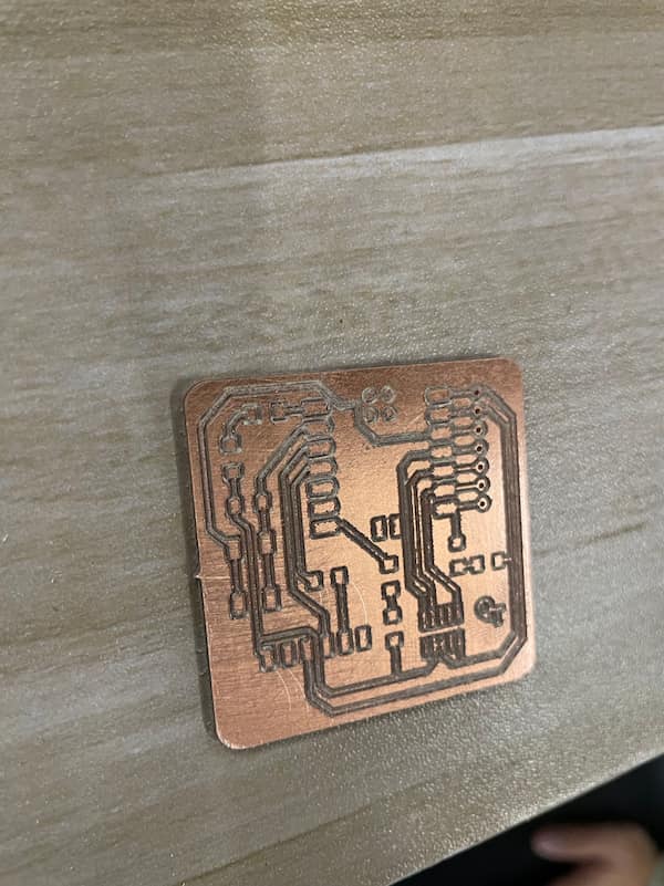
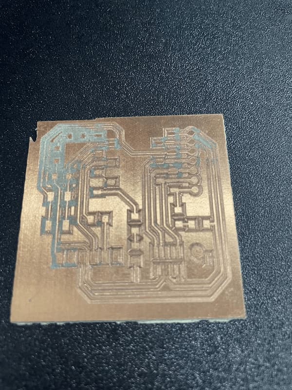
After cutting I got the board:
Rub with sandpaper to finish shaping:
Cut the board with G-code from the Alphacam using Gerber files
There is a software called: Alphacam and it can convert the Gerber file into G-code and can be also recognized by the CNC machine.
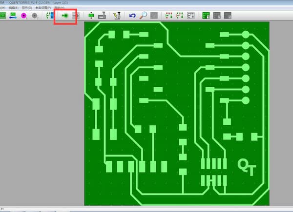
Import the "quentorres_v2-F_Cu.gbr" as the traces cutting, "quentorres_v2-PTH.drl" as the drilling, "quentorres_v2-Edge_Cuts.gbr" as the edge cutting:
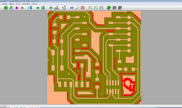
Click this button then choose the parameters, after a while it will output a picture of what it looks like after the cutting:
After converting all the files, I click the "Start" button, the machine will begin the cutting:
As you can see the traces are more complicated, which is not very good. This must contain some parameters wrong.
Finally, the board is looking like this:
Maybe it can still work if solder it carefully.
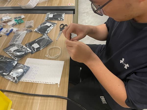
Solder and test the board with components
Soldering the components on the board
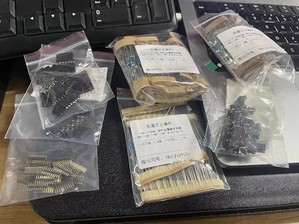
I first need to purchase the required components. In China, the description might be a little different, so I looked for reference, and then order them from the store:
| Component | Quantity |
|---|---|
| XIAO RP2040 | 1 |
| 1.27mm 间距 2*10P 排针双排贴片直针插件连接器 | 1 |
| 2.54mm 间距 1*6P 排母插件连接器 正为脚 | 1 |
| 轻触开关 4脚贴片 | 1 |
| LED 贴片发光二极管 | 3 |
| 1000 欧姆 1/4W 电阻 | 4 |
| 499 欧姆 1/4W 电阻 | 1 |
| 2.54mm 单排立贴排母 7P | 2 |
And finally I have them all:
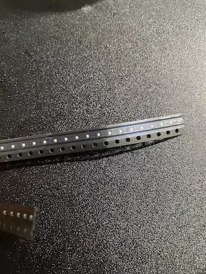
The resistance are different but good enough. The only problem that is the LED, this is REALLY REALLY REALLY small:
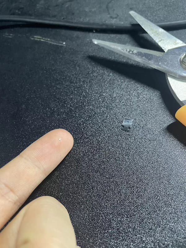
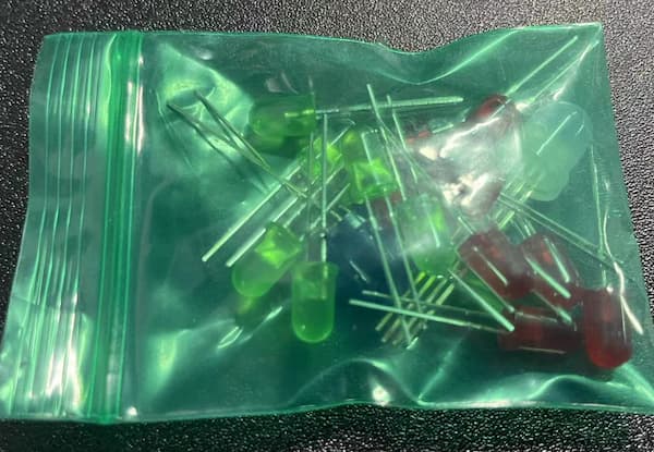
So I grab some simple leds from the office:
From the schematic diagram from the Quentorres:
I understand how to assemble them, and I decided to begin with the R1 (1K resistance) and here is the video about the progress of the soldering:
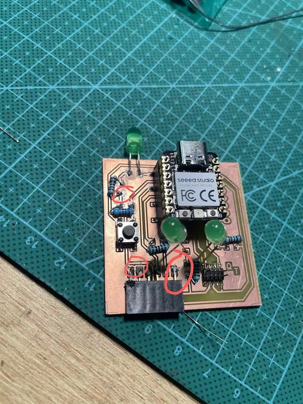
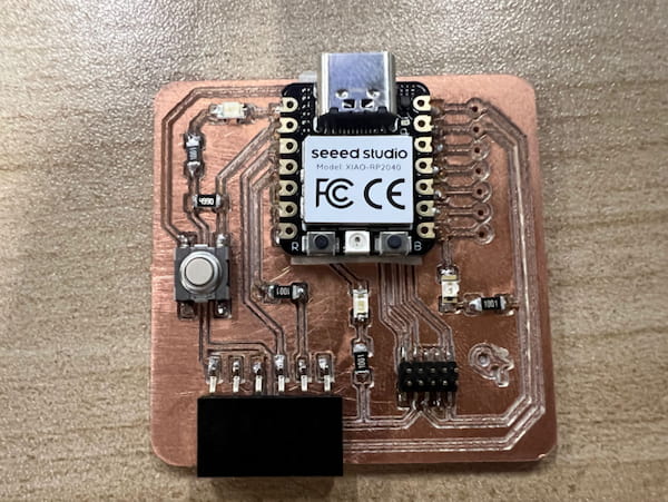
Here is the final result:

I am not very good at the soldering, here are some parts I am not doing very well(Too much tin, which may have short-circuited the copper):
Test the board
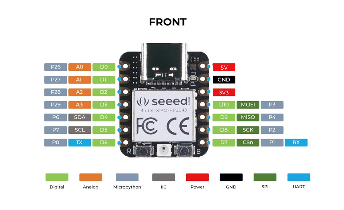
Reading the schematic diagram of XIAO RP2040 and the designed board. I understand there are three leds connecting the board which are PIN 0, 1, 26.
This the the code for the testing, to let the led light up:
int buttonstate = 0;

void setup() {
  pinMode(26, OUTPUT); // initializing the LEDs
  pinMode(1, OUTPUT);
  pinMode(0, OUTPUT);

  pinMode(27, INPUT); // initializing the tactile switch

}

void loop() {
  buttonstate = digitalRead(27); // returns whether button is on or off
  if (buttonstate == HIGH) {
    // turn LED on:
    digitalWrite(26, HIGH);
    digitalWrite(1, HIGH);
    digitalWrite(0, HIGH);
  }
  else {
    // turn LED off:
    digitalWrite(26, LOW);
    digitalWrite(1, LOW);
    digitalWrite(0, LOW);
    }

}
I have the outcome is:
The only lighted led is D2 and the the light was very faint. I thought the resistance maybe too much and the current passed the LED become very too small for the diode led to light up. Will test it later.
Written on 4.21st, this is my first time completing whole individual assginment by myself. From reading the materials, buying the products, assembling, programming... - Really fun! I have so much want to say! But I do need to get hurry. I have others that need to be completed. This is a competition me versus me, and I do want me to win:D
Updated on 5.15th
Written on 5.15th, watching me my previous words is really fun.
Anyway, after I got the board, with the help from my tutor.
Then I am trying to find the right components from the lab:
Later I got all components needed:
Now the power of soldering!
I have the complete board:
And I just use blink example to test it. Since the LED is connecting to the D0 to the XIAO RP2040 board. I do a little bit change:
void setup() {
  // initialize digital pin LED_BUILTIN as an output.
  pinMode(D0, OUTPUT);
}

// the loop function runs over and over again forever
void loop() {
  digitalWrite(D0, HIGH);  // turn the LED on (HIGH is the voltage level)
  delay(1000);                      // wait for a second
  digitalWrite(D0, LOW);   // turn the LED off by making the voltage LOW
  delay(1000);                      // wait for a second
}
And the final output is really nice:
And then I add the button in the function, of which the port is D1, or 27.
void setup() {
  // initialize digital pin LED_BUILTIN as an output.
  pinMode(D0, OUTPUT);
  pinMode(27, INPUT);
}

// the loop function runs over and over again forever
void loop() {
  int buttonState = digitalRead(27);

  if (buttonState == HIGH) {
    // 如果按钮被按下,点亮所有LED
    digitalWrite(D0, HIGH);
  } else {
    // 否则,熄灭所有LED
    digitalWrite(D0, LOW);
  }            // wait for a second
}
Generated by GPT. And the output is:
Fun assignment.