Blot
Write something at the front
In this group assignment, we are going to reimplement the BLOT, the plotting bot from hack club, presented by our friend - Leo and his teammates.
The Seeed Studio is hosting a Maker Camp event and at the first we invited 10 MIT researchers to co-create meaningful and open source hardware projects in Shenzhen, explore the tech ecosystem frontier, and join maker networks to explore the local scaling power. Leo was joining us and sharing his idea with us.

Hardware Assembling Part
Since the 3D printing parts are done and we are coming to an integration point. The material collection phase is really time-consuming.
We tried to unload other parts and reuse their components:
and it doesn't work out:
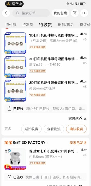
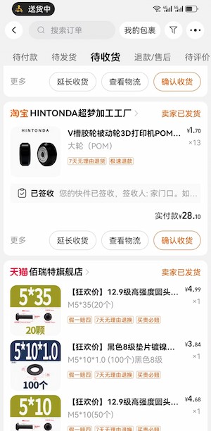
Later we have to refer to the material list here, and try to order them online:
There are still parts we are missing:
and we start to disassemble our 3D printers(some parts are just hard to order):
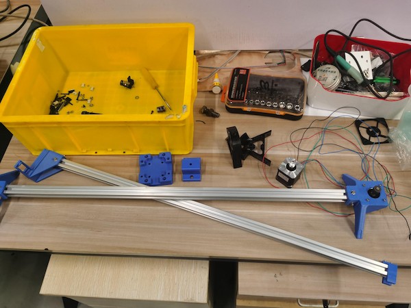
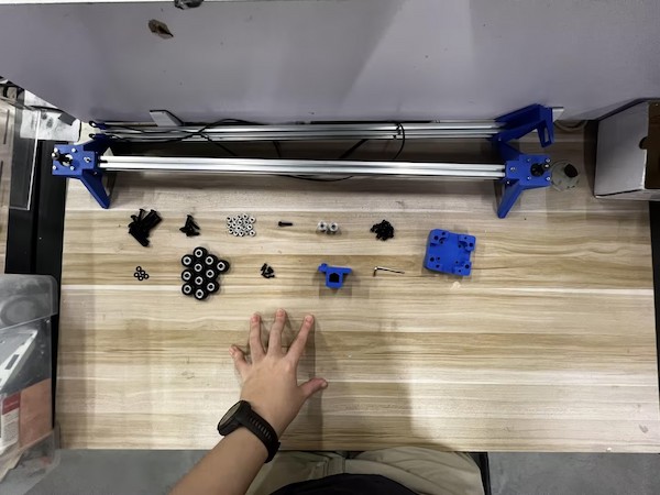
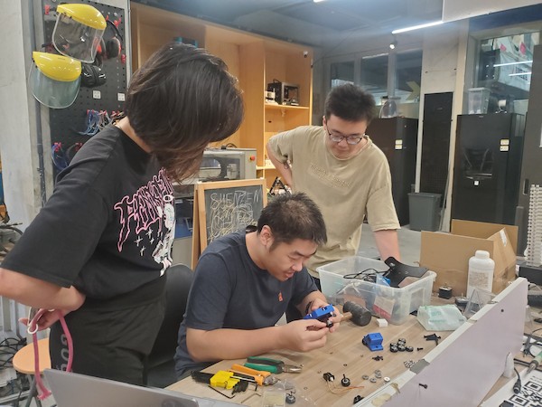
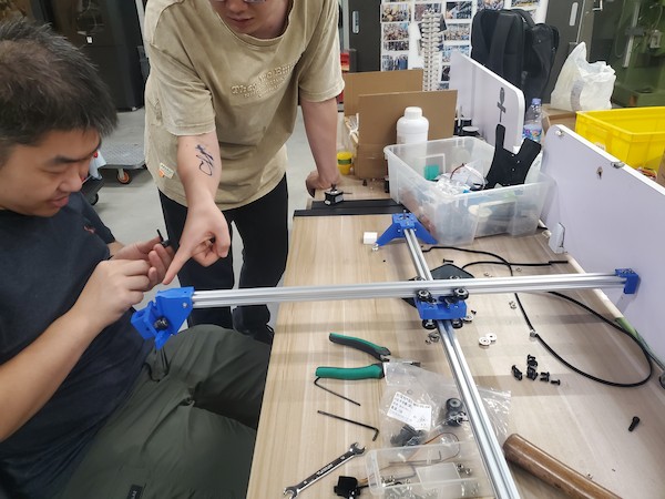
Finally we got almost all the parts and start to assemble:
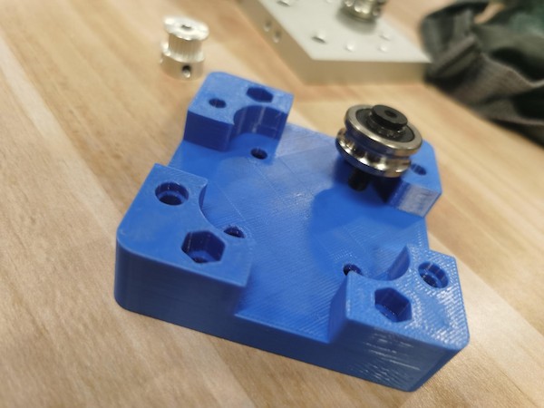
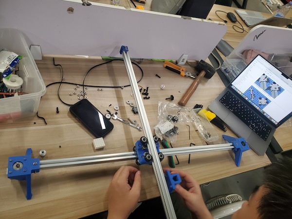
The main one:
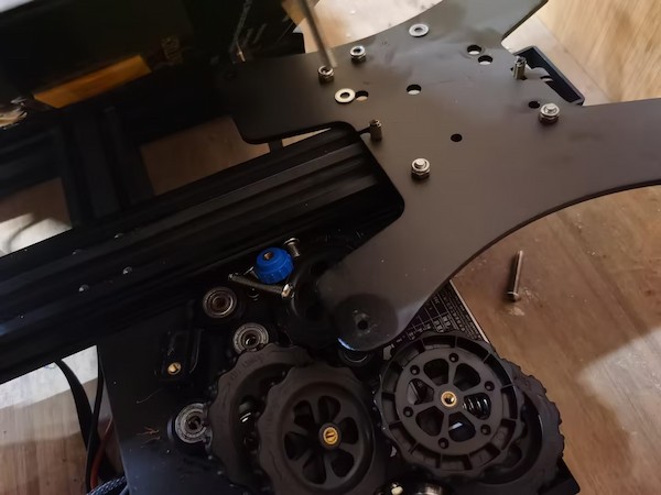
Add the main middle part to the Aluminum Extrusion:
looking good:
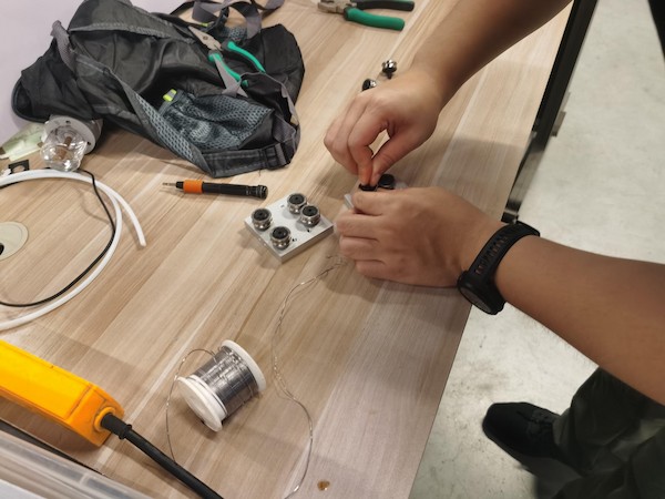
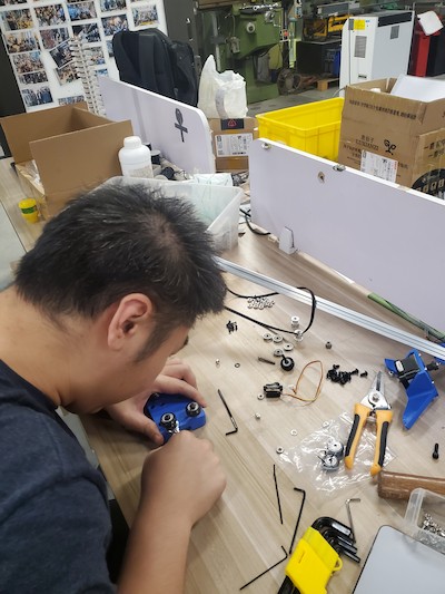
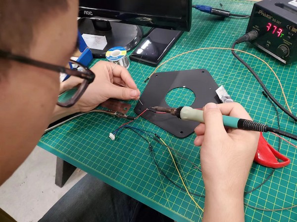
Then we can move to the part securing the pen:
Fix the servo motor:
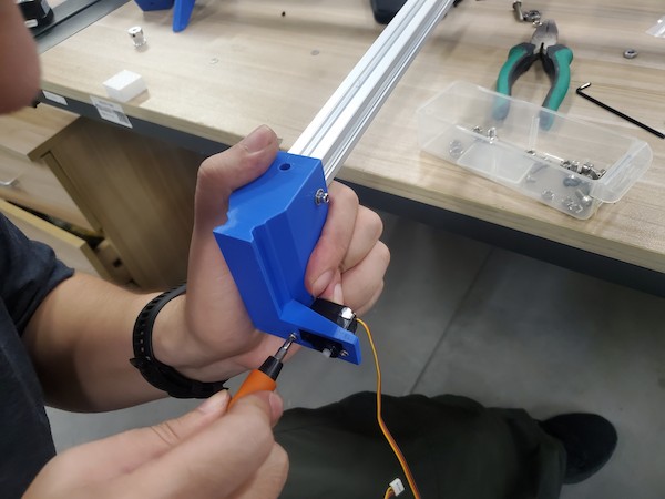
Done!! XD
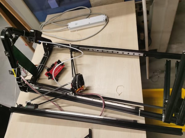
Ops! The belt not long enough!
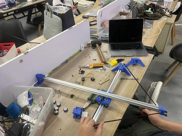
Why... It is becasue we are having much longer Aluminum Extrusion, which is almost 800mm. And the original one is 250mm...
This we think might cause some problems... like the equilibrium problem...
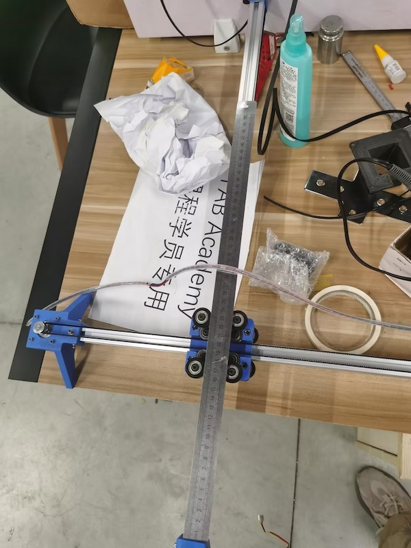
Anyway, later we are able to find the right length belt and assemble it as well:
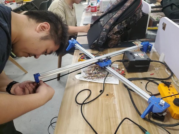
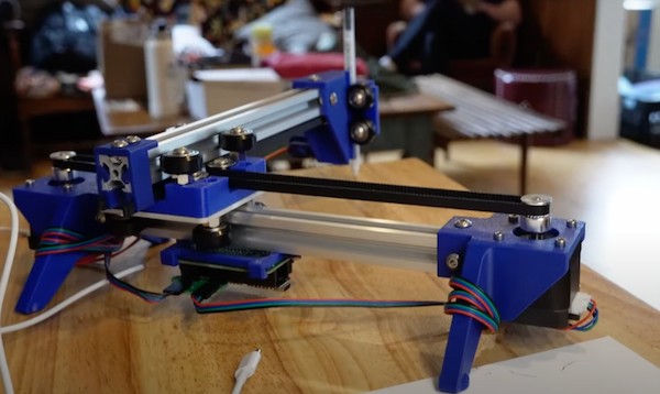
Assembling Done!
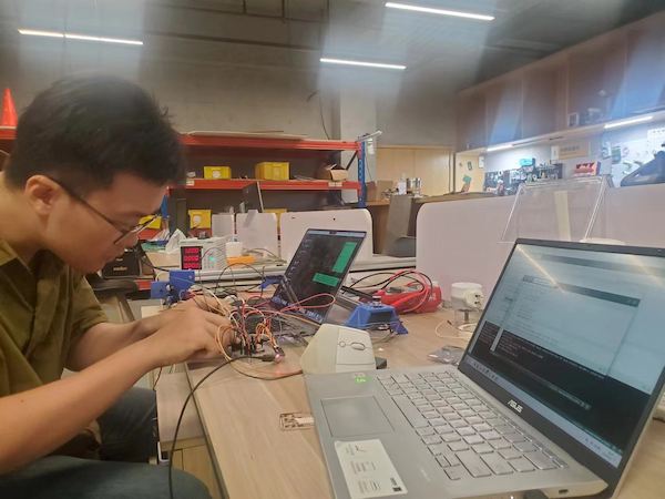
Hardware and Software Testing
For the next, I am going to test whether the hardware is functional and program the software.
Knowledge about the Kit
But at the fitst, we think we should know some principles.
System Integration
- Stepper Motor: It is used to control the movement of the X and Y axes. Each motor is connected to a shaft, which is rotated to move the corresponding shaft.
- Belt: It is attached to the stepper motor, used to convert the rotational motion of the motor into linear motion.
- Guide Rails(Aluminum Extrusion) and Sliders: Used to support and guide the linear movement of the platform on the X and Y axes.
- Controller: Usually a microcontroller or computer that sends a pulse signal to the stepper motor driver, thereby controlling the stepping and direction of the motor.
- Stepper Motor Driver: accepts the pulse signal of the controller and drives the stepper motor to move accurately
Operating Principle
Each stepper motor controls its rotation Angle through a pulse signal. The rotation of the stepper motor is converted into the linear motion of the platform by the belt system. THe operating can be simple:
Initialization: When the system starts, the controller moves the platform to the initial position (usually detected by a limit switch).Receive Instructions: The controller receives coordinate instructions entered by the user (for example, G-code instructions sent from computer software).Sending Pulse Signals: The controller sends a pulse signal to the stepper motor driver, which converts the pulse into the motion of the stepper motor. Linear motion: The stepper motor rotates to drive the lead screw or belt to move the platform to the specified position on the X and Y axes.- In this case,
XIAO RP2040will send pulse signal toA4988motor driver and the drivers will convert the pulse into the motion of the stepper motor. Calculation Path: Based on the current position and target position, the controller calculates the number and direction of pulses that need to be sent to each motor.
Since it is similar to the 3D printer principle, I will add some principles about these operating here as well:
Feedback and Adjustment: Some advanced systems may have a position feedback mechanism (such as a grating ruler) to ensure that the platform reaches the target position precisely. If deviations are found, the system fine-tunes them.
Controlling Methods
There are different methods can control the the motor. And the key to control the stepper motor is to control the frequency and number of pulse signals:
Single-step Control: Each pulse signal drives the motor to rotate at a fixed Angle (called a step). The motor is controlled to rotate multiple steps by sending multiple pulse signals.Microstep Control: Improve the resolution and accuracy of the motor by subdividing each step. For example, one step is subdivided into 16 microsteps.Speed Control: Control the rotation speed of the motor by adjusting the frequency of the pulse signal. A high frequency pulse will make the motor spin faster, and a low frequency pulse will make the motor spin slower.Acceleration control: In order to avoid sudden start or stop damage to the mechanical structure, it is usually necessary to perform acceleration control on the motor to smoothly start and stop.
Connection about the kit
Refering to this article.
We are going to use only two pins (STEP and DIRECTION) to control the stepper motors. The stepping pin is connecting to D10 of XIAO RP2040, used to control the step, while the directional pin is connecting to D9 of XIAO RP2040, used to control the direction. The stepper motor is powered by 12V power supply, and the A4988 module is powered by XIAO RP2040. Potentiometers are used to control the direction of the motor.
Hence, this is will be the motor 1 connection method:
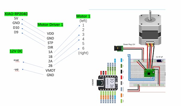
For motor 2 connection, the only change is that The stepping pin is connecting to D10 of XIAO RP2040 while the directional pin is connecting to D9 of XIAO RP2040.
To sum up, it will require one XIAO RP2040 to control two motors.
Software Programming
Testing Code
This is Arduino code, for drawing a oblique line, operating motors, moving the same time on the X-axis and Y-axis.
#include <Arduino.h>

const int STEP_PIN_X = D10;
const int DIR_PIN_X = D9;
const int STEP_PIN_Y = D8;
const int DIR_PIN_Y = D7;

const float STEPS_PER_MM = 80.0; // Adjust this value based on your stepper motor's steps per millimeter
const float LINE_LENGTH_MM = 100.0; // Length of the line in millimeters

void setup() {
  pinMode(STEP_PIN_X, OUTPUT);
  pinMode(DIR_PIN_X, OUTPUT);
  pinMode(STEP_PIN_Y, OUTPUT);
  pinMode(DIR_PIN_Y, OUTPUT);
}

void loop() {
  // Draw a line along the X-axis
  drawLine(0, 0, LINE_LENGTH_MM, 0);

  delay(1000); // Pause for 1 second

  // Draw a diagonal line
  drawLine(0, 0, LINE_LENGTH_MM, LINE_LENGTH_MM);

  delay(1000); // Pause for 1 second

  // Move back to the origin
  drawLine(LINE_LENGTH_MM, LINE_LENGTH_MM, 0, 0);

  delay(1000); // Pause for 1 second before repeating
}

void drawLine(float x0, float y0, float x1, float y1) {
  // Convert millimeters to steps
  int x0Steps = round(x0 * STEPS_PER_MM);
  int y0Steps = round(y0 * STEPS_PER_MM);
  int x1Steps = round(x1 * STEPS_PER_MM);
  int y1Steps = round(y1 * STEPS_PER_MM);

  int dx = abs(x1Steps - x0Steps);
  int dy = abs(y1Steps - y0Steps);

  int sx = (x0Steps < x1Steps) ? 1 : -1;
  int sy = (y0Steps < y1Steps) ? 1 : -1;

  int err = dx - dy;

  while (true) {
    if (x0Steps == x1Steps && y0Steps == y1Steps) break;

    int e2 = 2 * err;

    if (e2 > -dy) {
      err -= dy;
      x0Steps += sx;
      digitalWrite(DIR_PIN_X, (sx > 0) ? HIGH : LOW);
      digitalWrite(STEP_PIN_X, HIGH);
      delayMicroseconds(500);
      digitalWrite(STEP_PIN_X, LOW);
      delayMicroseconds(500);
    }

    if (e2 < dx) {
      err += dx;
      y0Steps += sy;
      digitalWrite(DIR_PIN_Y, (sy > 0) ? HIGH : LOW);
      digitalWrite(STEP_PIN_Y, HIGH);
      delayMicroseconds(500);
      digitalWrite(STEP_PIN_Y, LOW);
      delayMicroseconds(500);
    }
  }
}
Here is the principle:
Stepper Motors:
- For Motor 1:
- Connect the motor driver's STEP pin to the XIAO RP2040 board's pin
D10(defined asmotor1StepPinin your code). - Connect the motor driver's DIR pin to the XIAO RP2040 board's pin
D9(defined asmotor1DirPinin your code).
- Connect the motor driver's STEP pin to the XIAO RP2040 board's pin
- For Motor 2:
- Connect the motor driver's STEP pin to the XIAO RP2040 board's pin
D8(defined asmotor2StepPinin your code). - Connect the motor driver's DIR pin to the XIAO RP2040 board's pin
D7(defined asmotor2DirPinin your code).
- Connect the motor driver's STEP pin to the XIAO RP2040 board's pin
- Ensure that the motor driver's power supply is connected correctly and matches the voltage requirements of the stepper motors, which is 12V.
System Composition
- Stepper motors: The
STEP_PIN_X,DIR_PIN_X,STEP_PIN_Y, andDIR_PIN_Ypins are connected to the XIAO RP2040 to control the movement of the X and Y axes, respectively. - Controller (XIAO RP2040): Send pulse signals to the stepper motor to achieve linear motion by adjusting the rotation of the stepper motor.
How it Works
- Initialization: In the
setup()function, use thepinModefunction to set the pins that control the stepper motor to output mode. - Receive instructions:
The loop()function loops through thedrawLineX()anddrawLineY()functions, sending instructions to control the motor to move a specific distance along the X and Y axes. - Calculate the path: In the
goToMM()function, convert the number of millimeters at the destination location to the number of steps, usinground(x * STEPS_PER_MM)andround(y * STEPS_PER_MM)to calculate the number of steps to be sent. Send a pulse signal: In the goToMM() function, use the digitalWrite function to send a pulse signal to control the stepper motor to move to the target position.
Control Methods
- Single step control: By
digitalWrite(STEP_PIN_X, HIGH)anddigitalWrite(STEP_PIN_X, LOW)anddigitalWrite(STEP_PIN_Y, HIGH)anddigitalWrite(STEP_PIN_Y, LOW)Control the stepper motor to rotate one step. - Direction control: use
digitalWrite(DIR_PIN_X, (xSteps >= 0)? HIGH: LOW)anddigitalWrite(DIR_PIN_Y, (ySteps >= 0)? HIGH: LOW)Sets the rotation direction of the motor. - Speed control: The frequency of the pulse signal is adjusted by
delayMicroseconds(500)to control the rotation speed of the motor.
Code Interpretation
- setup() function: Sets the stepper motor control pin to output mode.
- loop() function: Execute the drawLineX(), drawLineY(), and goToMM(0, 0) functions in order to move a certain distance along the X and Y axes, respectively, and then return to the origin.
- drawLineX() and drawLineY() functions: Call the goToMM() function to move the specified distance along the X and Y axes, respectively.
- goToMM() function: Converts millimeters to steps.
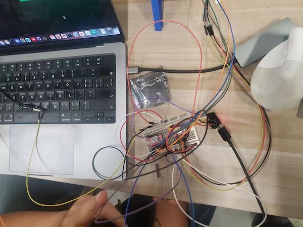
Real Connecting
This is really hard one.
We are using one XIAO RP2040, two A4988 motor divers, and two step motors, and connecting them on one breadboard, for the testing.
First, we need longer wires...
Then I refer to this article before, and connect the components with the example connection.
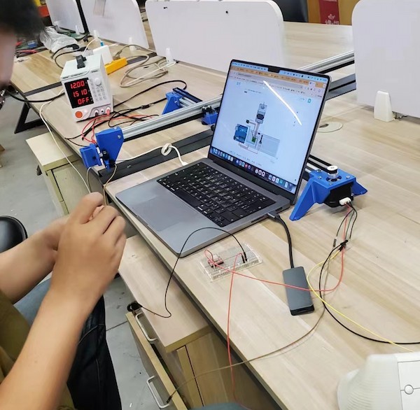
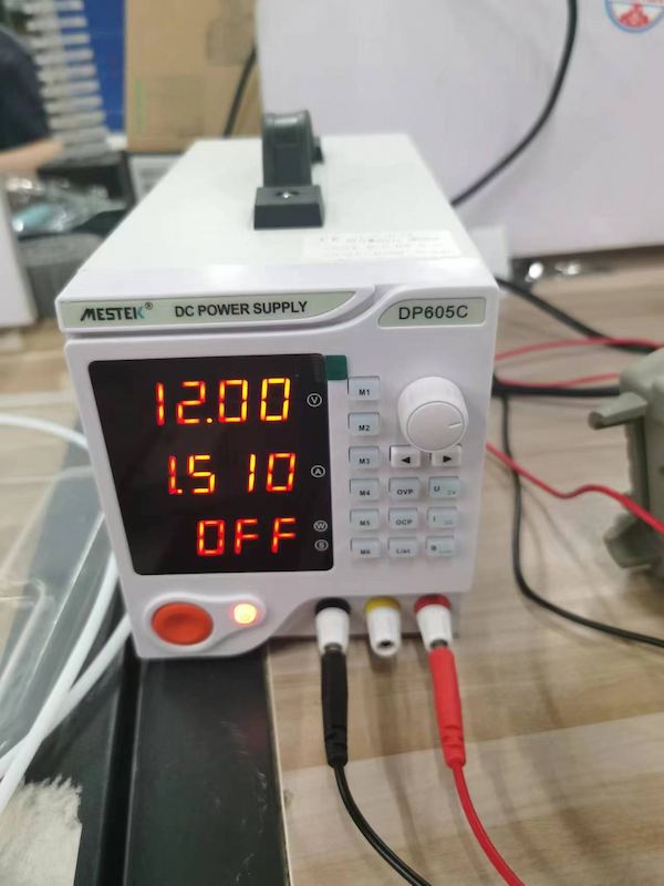
For 12V power supply, I am using a DC power supply, setting 12V.
Connecting XIAO RP2040 and the A4988 motor diver, with schematic diagram.
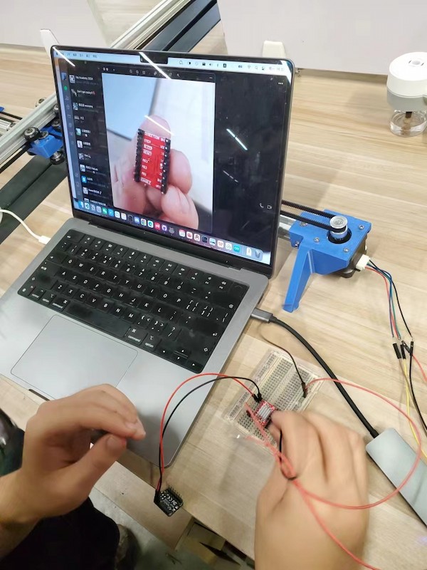
Done for motor 1.
Upload a simple code for testing there is no short circuit.
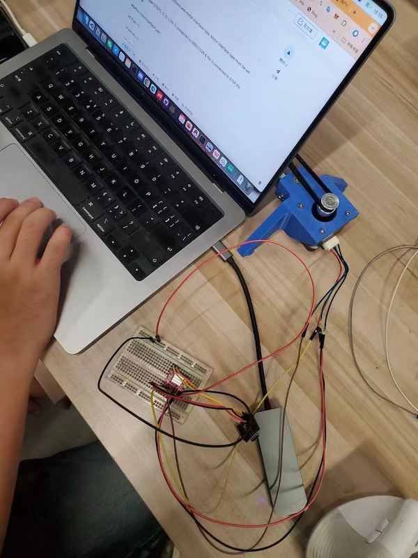
Then connecting another one:
After burnning 3 drivers... and keeping wrong moving...
debugging...
Connection lost - not holding well.
debugging...
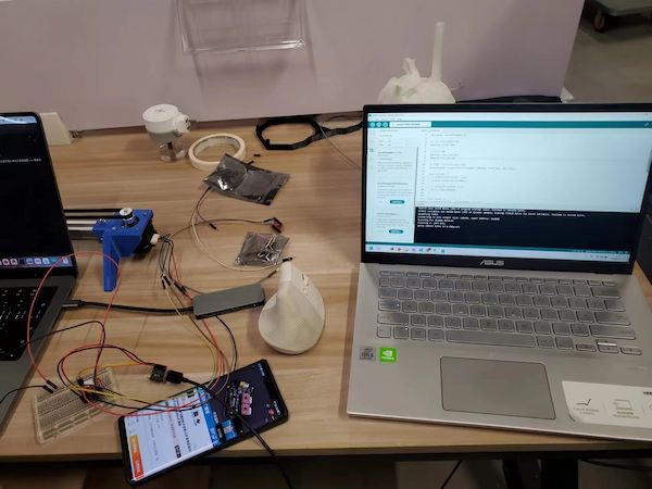
Stuck - adjust the pulley
I got the final version of connection at last:
And testing finally good: