Simple Blackboard
Write something at the front
Updated on 7.13rd, I was visiting another company for my final cut and learning some stuffs.
Later our group was given a training about using CNC machine in the ChaiHuo and I have written the contents regarding them in my Group Page.
File Sharing
Cutting in the ChaiHuo Lab
This is the Machine we using for CNC cutting in ChaiHuo:
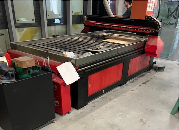
Its brand name is ZhongTaiKe and the manufacturer has gone out of business right now... But the machine is still work.
Knowledge about the CNC cutting
For the group trainning, i understand the big CNC cutting technological process:
- Safety first.
- Return the machine to its mechanical origin, and manually set the speed(15000mm/min) then look for zero point. Testing it whether is fine.
Here we using 5000mm/min and 8mm milling to do the test cutting.
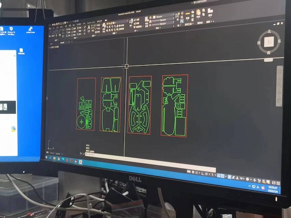
- Then I should use related software(for this is MaserCAM X6) to convert my DXF design to G-code:

2.1. We are putting all our files in one place(but will be in 4 g-code files):
2.2. Then create the tool, an 8mm diameter tool. Set the tool parameters as follows: rotational speed 15000 mm/min, feed rate 5000 mm/min, plunge rate 500 mm/min.
Keep the cutting depth as default(for the cutting board is 1.2m x 2.4m). Set the safety height to 50mm(In the end, the mechine will lift to 50mm), the feed plunge position to 3.0, and the depth to 18mm(the thickness of cutting board).
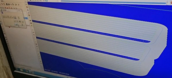
2.3. Generate tool path after setting. Take my board as example:
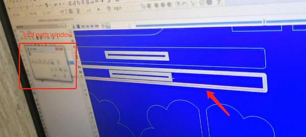
This one is cutting from the outside and it is not right.
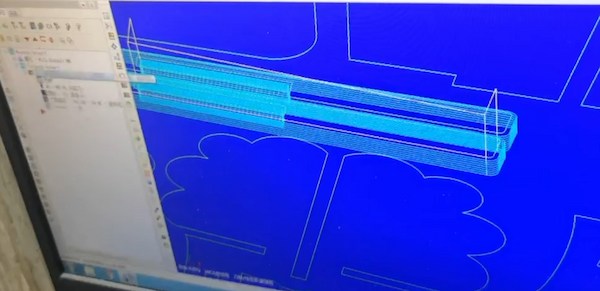
This is right one:
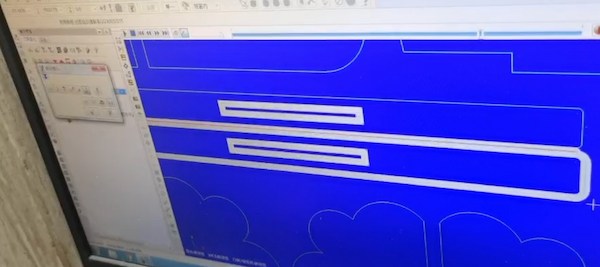
2.4 Finally simulate the path. Without broken line I can generate the G-code.
- For real cutting is easy since it is set up already.
3.1 Setting up the board and holding it up tight:

3.2 Upload the code file and starting the cutting:
3.3 This is actually mine(the portions):

We have four boards for cutting.
- Finally I can assemlbe them:
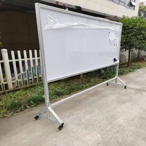
Done and hero shot:

Design on the Onshape
Updated on 6.29th, I just updated the assignment since I want to build a blackboard, for the future presenting my work.
I am thinking a simple one, with simple connection between each part.
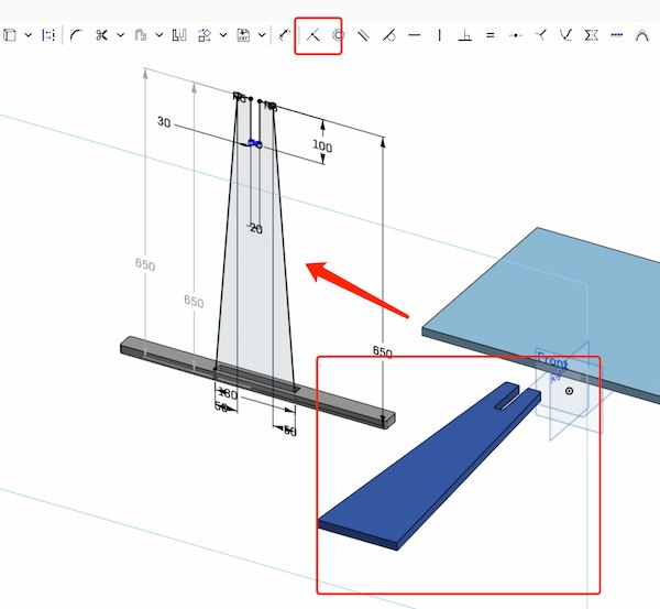
For the first it is the main part:

I picked a spot on the side so my bracket could fit together:

In fact, my card should be based on the actual thickness of the board, so I set it to 20mm first, just in case.
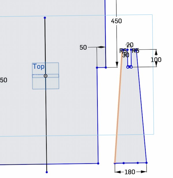
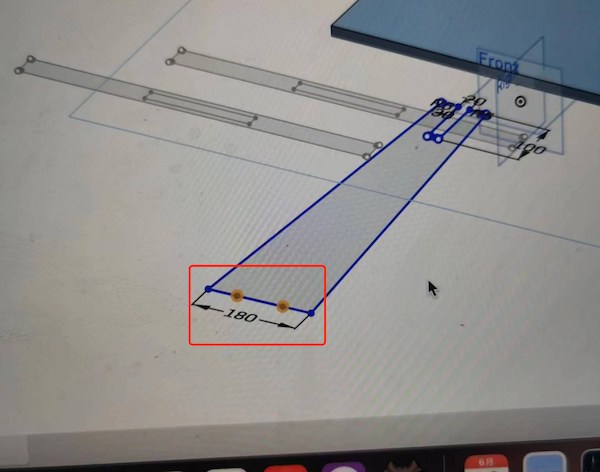
Then I used the "mirror" function to add a line in the middle and duplicate the bracket next to the other one.

But for the sake of material conservation, I think it's better to line up the top and the bottom:
But I don't think this trapezoid bottom is gonna be big enough to support the main board:

I then design another bottom, for holding the supporting.

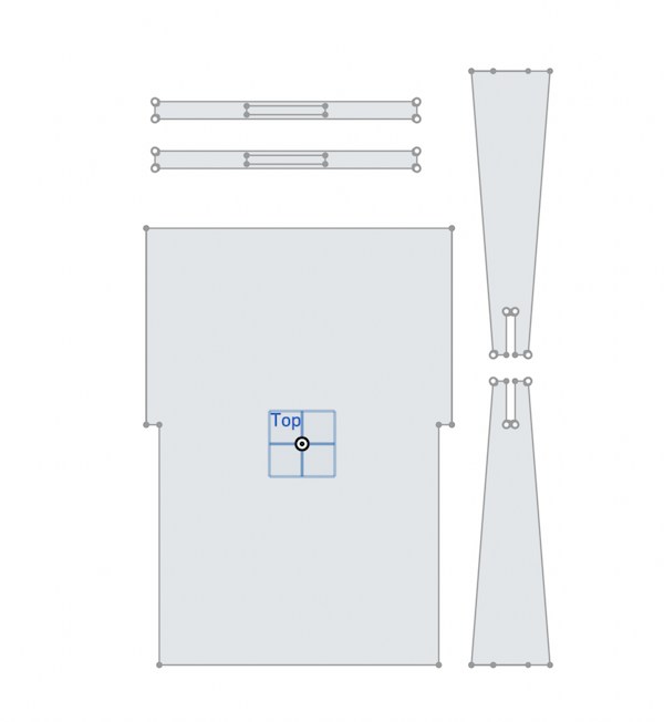
Then I use mirror function again for creating a new one:

Finally, I have my 2D design.
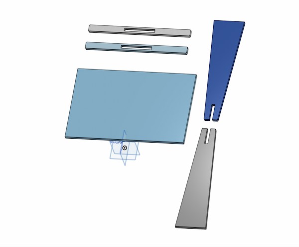
While generating the 3D image, I suddenly realized that I didn't really need the bottom of the main board. I don't really use the bottom part.

Hence, for material saving, I am delecting that part:
Before starting to sending to the CNC machine, I should make sure that my design can be assembled. I'm using a computational method to calculate the parts of joint:
- Found a part in the control that allows me to create a new sketch

- My plane drawing is based on the new sketch for part design
- Make sure each point is aligned and error-free.

Now the final part is done, I have the DXF files(2D design) and STEP file(3D deisng). I can use the CNC machine to cut it.
Knowledge about the Large CNC Machines
When using large CNC machines for cutting, there are several key points, in process:
-
Choose the right CNC machine: Select a suitable CNC model based on the cutting size, material hardness, precision requirements, etc. Different models have varying power, rigidity, and accuracy parameters.
-
Use the correct CAD/CAM software: This is very important. There are various CAD design and CAM programming software available in the market, and different CNC machines may require specific post-processors. This is the reason I output both 2D files and 3D files at the same time.
-
Workpiece clamping and positioning: Wood is relatively soft and easily deformable, so clamping is crucial. Ensure that the workpiece is securely fastened and reasonably arrange the fixtures to avoid interference. Large workpieces may require multiple setups, so the positioning reference should be consistent(the zero point).
-
Tool selection and control: Choose suitable tool materials, number of flutes, and diameters based on the wood type and cutting requirements. Pay attention to controlling the tool overhang to avoid vibrations that affect machining quality. Check for tool wear before each use.
-
Cutting parameter setting: Set the spindle speed, feed rate, and cutting depth according to the wood hardness, tool type, etc. Usually, multiple debugging sessions are needed to find the optimal parameters.
To sum up, I need to choose the appropriate CNC machine and software based on specific requirements, draw the 3D model of the part using CAD, write the toolpath using CAM software to generate G-code, import the code into the machine, install the tools and properly clamp the workpiece, set appropriate cutting parameters.
Cutting in someone's factory(not very well)
This is the software I am using:
LeDiao Deisn H480.

The interface is very friendly and easy to deisn:

I can use this and convert my DXF files into G-code.
Knowledge Learn - G-code
G-code is the common name for the most widely used numerical control (NC) programming language, which is used to control automated machine tools. G-code is also referred to as G programming language. It instructs CNC (Computer Numerical Control) machines how to move, what paths to follow, and what actions to take regarding tool changes, coolant, and other machine-specific functions.
G commands: These are predefined geometric commands that tell the machine to perform specific movements. For example, G0 (rapid positioning) moves the machine tool rapidly to a specified position, and G1 (linear interpolation) moves the tool in a straight line at a specified feed rate.
M commands: These are miscellaneous predefined commands that control other functions of the machine, such as M3 to start the spindle turning clockwise, M5 to stop the spindle, and M30 to indicate the end of the program.
Coordinate values: X, Y, Z (for linear motion) and I, J, K (for arc centers) designate target positions or movement paths.
F command: Sets the feed rate, or the speed at which the tool moves.
S command: Sets the spindle speed, or the rotation speed of the tool.
T command: Used for tool selection, for example, T1 might select the first tool on the machine.
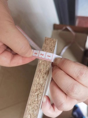
First of all, make a board that corresponds to my designed size, and the thickness of the real board thickness.
These will be the parameters of my designed board:
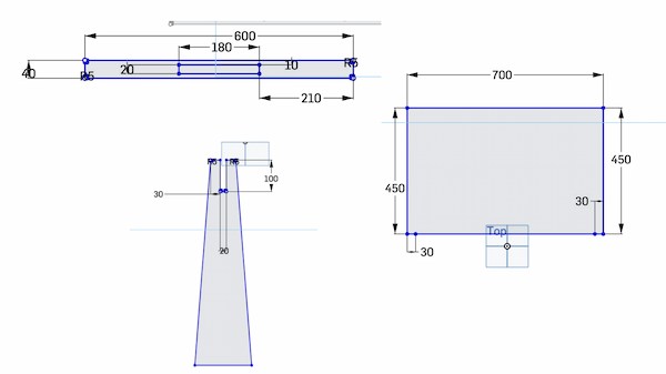
And the thickness of the real board is 18mm.
Then for the board settings:

The numbers here represent the maximum length(700mm), width(450mm) and height(18mm) of the board I need. After I upload the DXF file, it will automatically recognize my design drawing and fit the corresponding shape of my design under this maximum size.
I then upload my DXF of my main board to it, it will automatically attach to the real one. I then can upload my rest DXF files.
For DXF files gereating. It is important that there should be no extra lines. I upload my supporting boards and it failed. It is because I used to build extra lines to fix the sizes. I should delete them.
Later I have all the files I need:

Then I can move to the board working area setting:
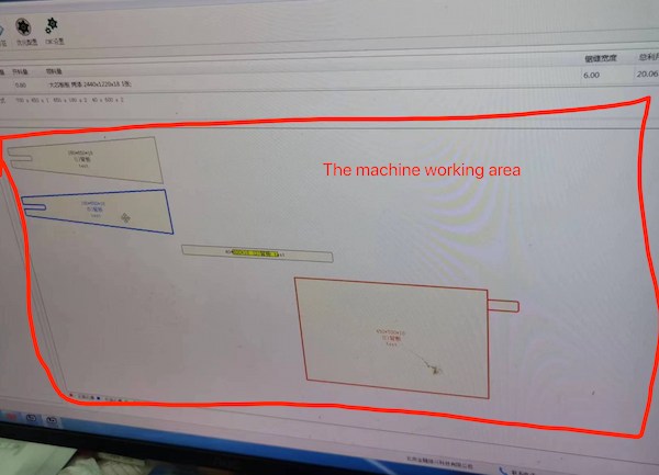
Design them in close area to reduce material loss:

Now I can generate the G-code for the machine.
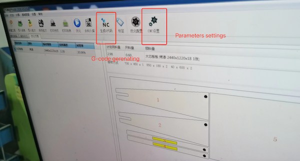
The neat thing of this machine that I can know where exactly of each board is:

Machine Usage and Board Cutting
Machine Overview
This is the machine I used:
CNC aluminum plate plus center SK1328-4A aluminum plate automatic cutting machine aluminum honeycomb plate welding and cutting machine

This is the page for machine purchasing and information details presenting.
These are the parameters:

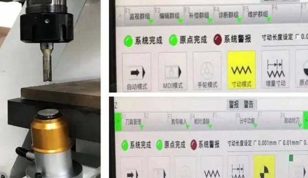
And it is the operating interface:
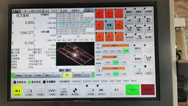
The rotational speed should be 18000 rpm, feed rate is 9600 mm/min and the plunge speed should be 1200mm/min.
The tool edge I used is 6cm 圆鼻车刀, which for English I think is 6cm Round nose turning tool. Reference by Zhihu and Baidu
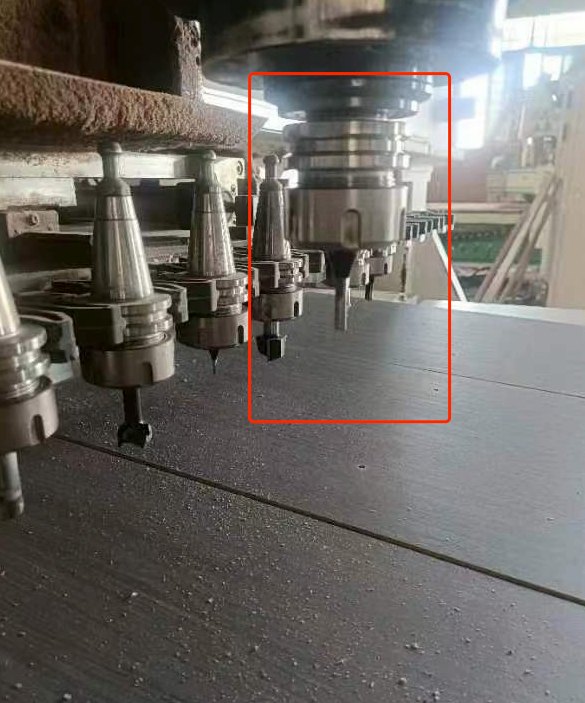
This blade is circular arc, can be turned in left and right direction, suitable for rounded corners or curved surfaces.
There are other drill, turning tool and milling-tool presenting, reference by here.
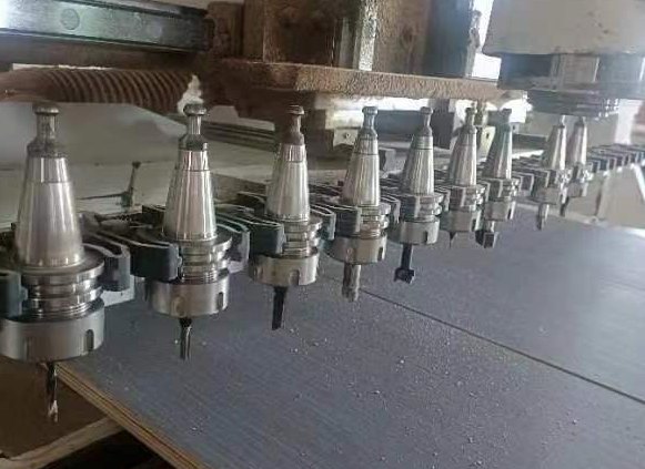
For starters, back to the zeron point:

Automatic tool setting.
Actually this machine is setting up and I can just uploading my G-code is fine. For more setting up, this is the reference.
Finally, the zero point is setting:
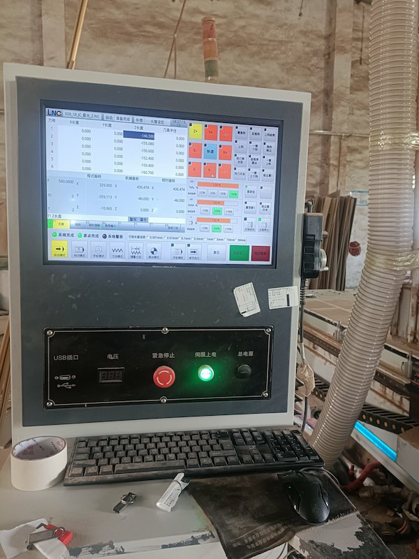
For this machine, I should save the code in a flash drive and insert it:

Remove the old files and upload the new files(mine):
This is the operating reference.
Next I should put the board on the operating table and securing it:
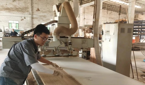
After everything is setting up, I can control and run it. It takes about 3 minutes, since my design is simple.
Assemble
After it is finished, I blowed away the wood chips and labeled the parts. For mine it is not necessary, but for others complicated, it is a good habit:
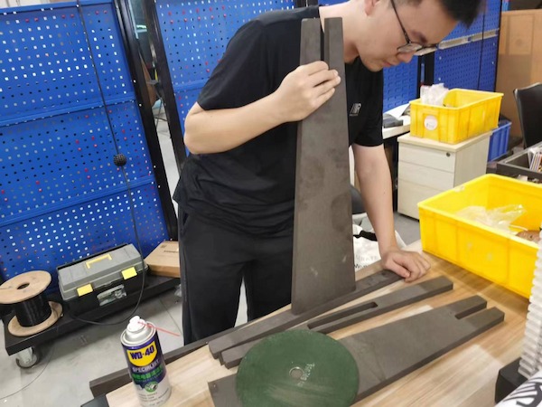
Later I found some issues about my design:
My bottom is a bottom with rounded corners, but my support plate is not designed with rounded corners, so even if the thickness is right, I can't plug it in.

So it needs to be polished with an Angle grinder.
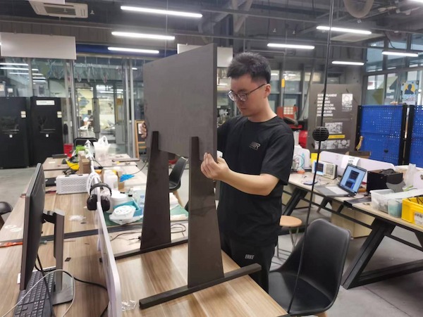
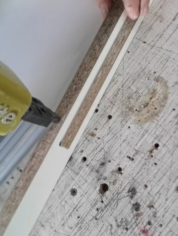
And because this is manual grinding, it can't guarantee standing after inserting it. So it's best to use a staple gun to secure the bottom.
Done and taking a nice picture:

Thanks the guys trainning me!