3D printing and 3D scanning
Write something at the front
Updating on 7.2nd, I am designing a module that is recommended by Additive Manufacturing and not by Subtractive Manufacturing.
Catching on 5.24th, I am designing my final project and I realize that I can do something for my power expansion board. This is too much:
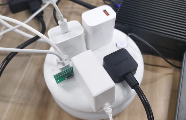
I want to design a cover to cover it all up.
Files Sharing
- The Onshape link for the design for recommended manufacturing by additiong is here
- The Onshape link for my cover design is here
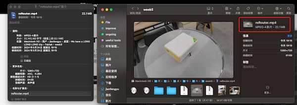
- The OBJ file generated by lumalabs is here
Preparation
First I need to think how can I make it work:
- The top of the cover should be able to jam/stick.
- The leaving room for line output at the bottom.
- The most important thing is that he needs to be close to this rotating box.
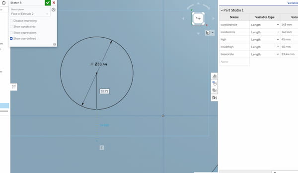
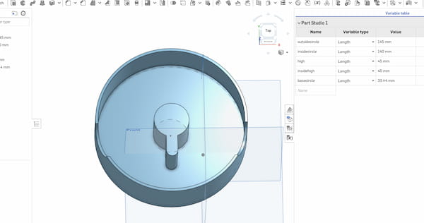
Then I check the size definition, since I am using the middle of the bottom, this part is important:
The stick part:
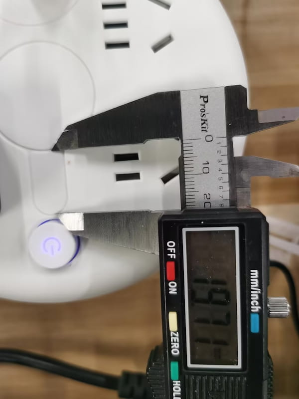
19.71mm
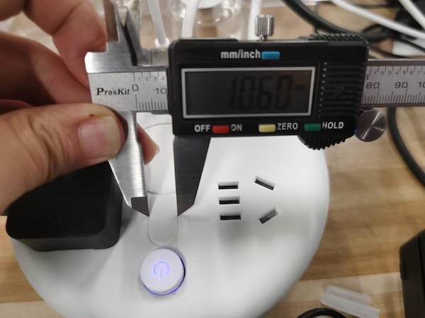
10.60mm
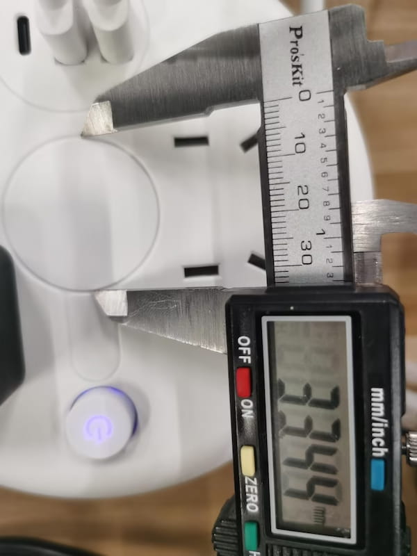
33.44mm
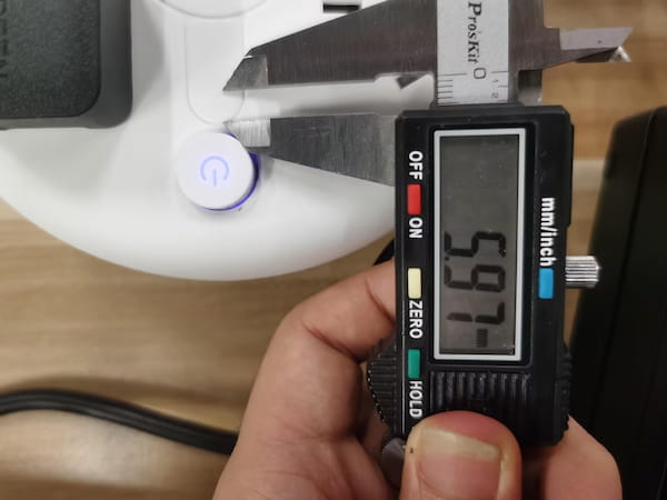
5.97mm
From the offcial manufacturer, I got the rest part parameters:
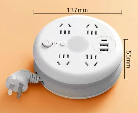
137mm x 55mm
The last thing is that I should look for extra space to cover it all up.
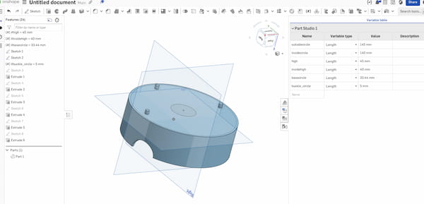
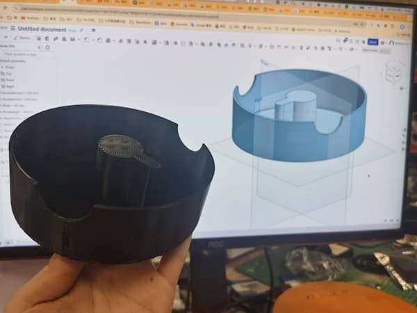
3D model design on OnShape
I decide to use onshape to build my 3D mdoel.
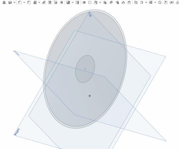
Fisrt it is the base design, considering the extra space.
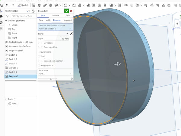
Then use extrude to build a cylinder. And on the top of that cylinder creating another sketch, using extrude again to remove the space to cover the plugs on the power extension board. This will make a simple basin.
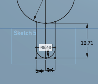
And then I can do the middle part that needs to be sticked:
The extended part, with 3 point arc(a) and Line function to draw it:
Then use Trim to cut the unrelated lines and use extrude to sync with enclosure.
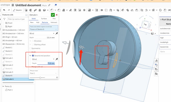
Next I design the part that needs to be cut off at the bottom, for the connectors output:

It looks like this, but there is a problem: Because I want to cut both sides symmetrically, but it also cuts out the middle.
There is a function called second end postion, it allows me remove through without the middle part.
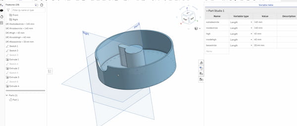
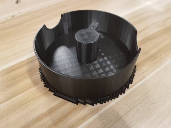
This is the "final" look like
And looking on the 3D printer code generation software.
Then I realize I want to add my 2D laser cutting image on it, I need extra space at the top to put my laser cutting design for it.
Hence, I add three bumps:
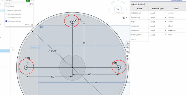
This will be the top of it:
3D printer using
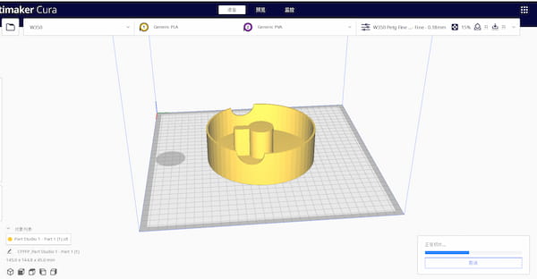
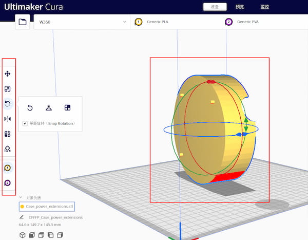
There is a software called: ultimaker cura and it can convert the ."stl" file to the software G-code.
It just need to import it and this will be the showcase:
Actually, there are different types to printing and different parameters to set up the printer. For example:
I can rotate 90 degrees to print the model upright:
Then find how is the printer printing:

It will take 10 and a half hours.
Then put it plane:
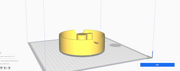
And the top(the cover) bump is showing as well:
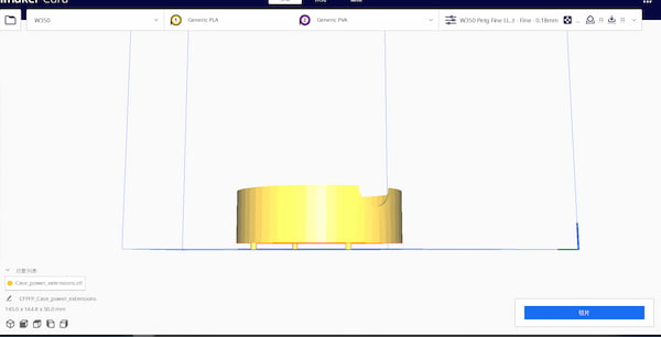
The priting is looking like this and it only takes 4 hours and 45 min

Hence I choose this way and let it output the G-code for me.
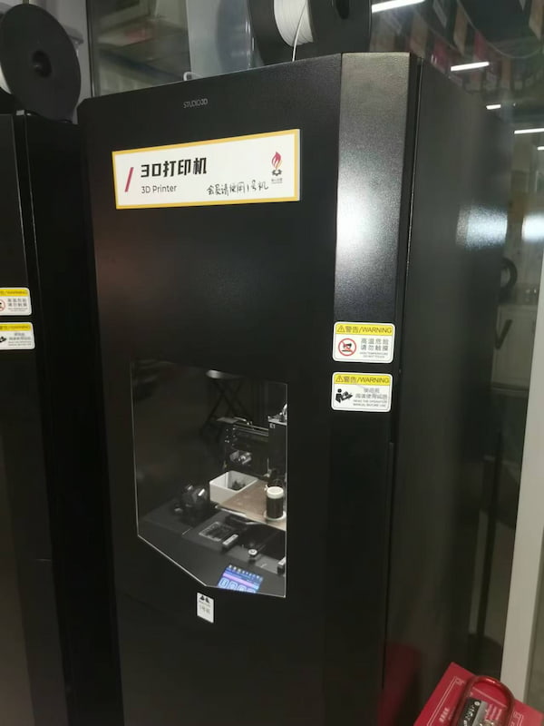
Using "STUDIO3D" 3D printer
This is the "STUDIO3D" 3D printer:
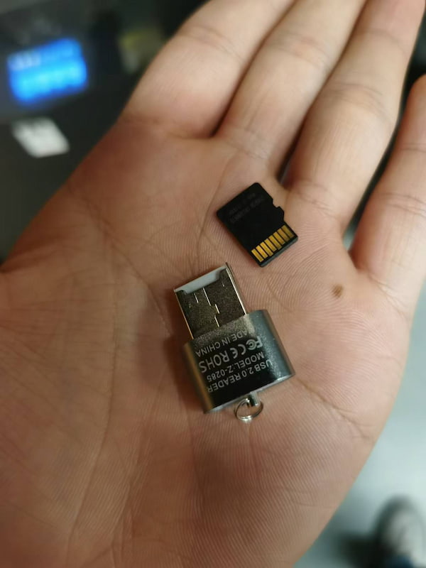
It requires micro SD card to upload the files:
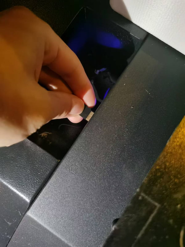
There is a micro SD card slot for it:
Insert it:
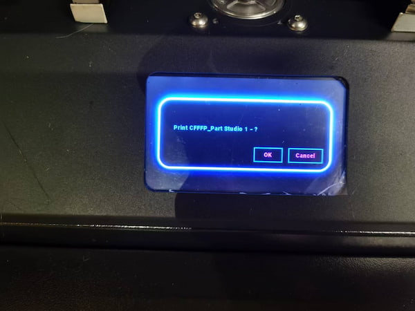
Start the printing:
But it is broken, for printing last one:
Using "Bambu Lab" 3D printer
This printer is really good! I am using "A1 mini" model:
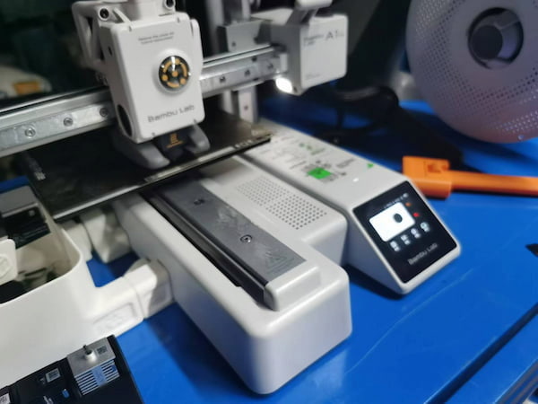
And this supports Wi-Fi data/file transmittion, with BambuStudio Software.
After installation, choosing "A1 mini"
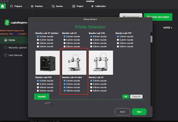
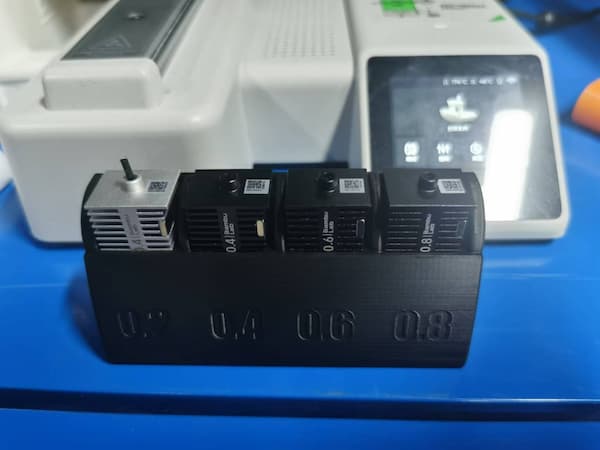
And select all four mozzles:
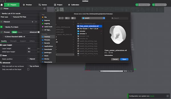
And then import my STL file
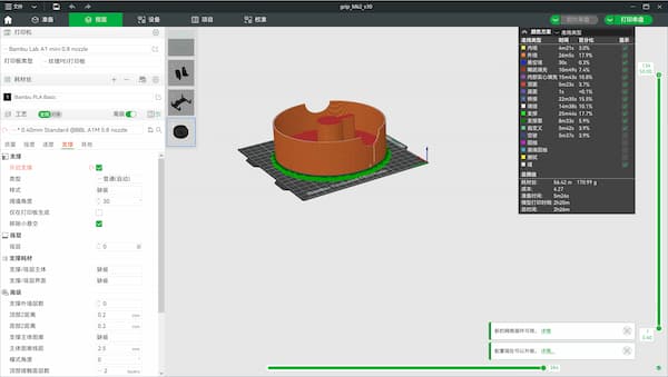
The setting parameters are quite a lot, but there no much need to set, I am using 0.8mm to print:
Then this file can be wireless sending to the printer.
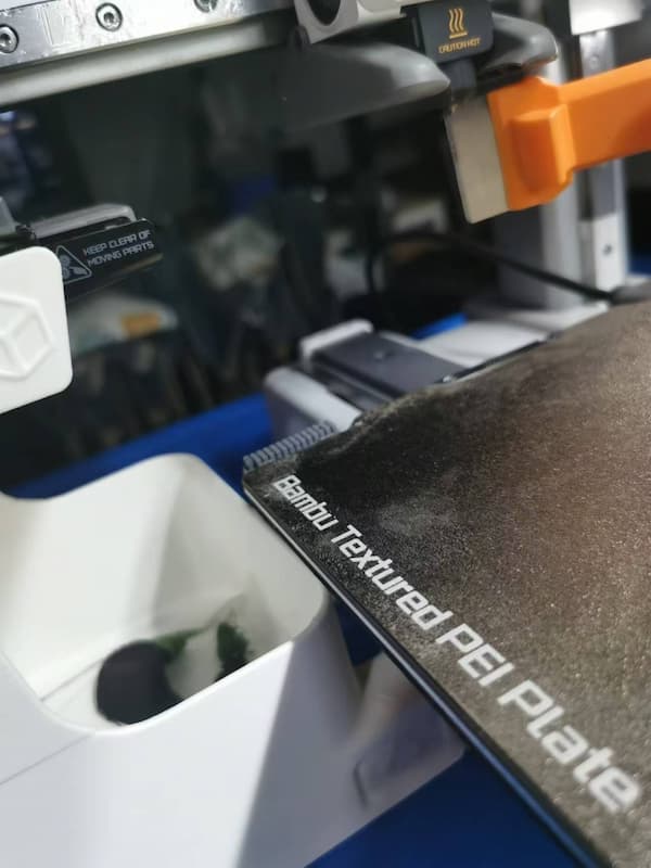
The printing material sometimes gets stuck in the blade, for using a relatively thin knife:
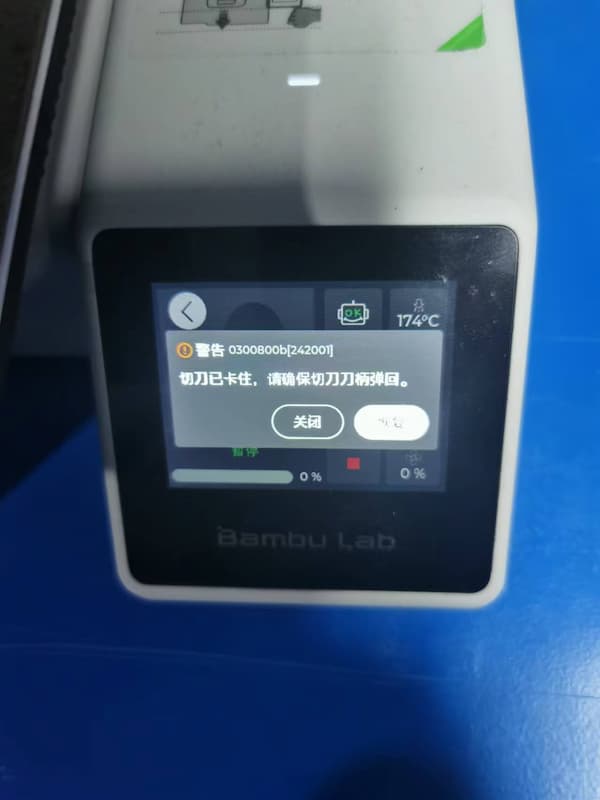
And requiring to remove it
After all setting up, the printer will begin to prtinting:
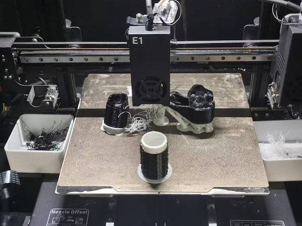
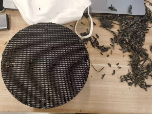
Afer almost three hours, I got the part:
But I need to remove the base material with needle-nose pliers(too hard, the material is too strong):
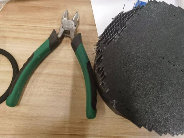
Remove one by one:


I can keep removing, but this is enough:
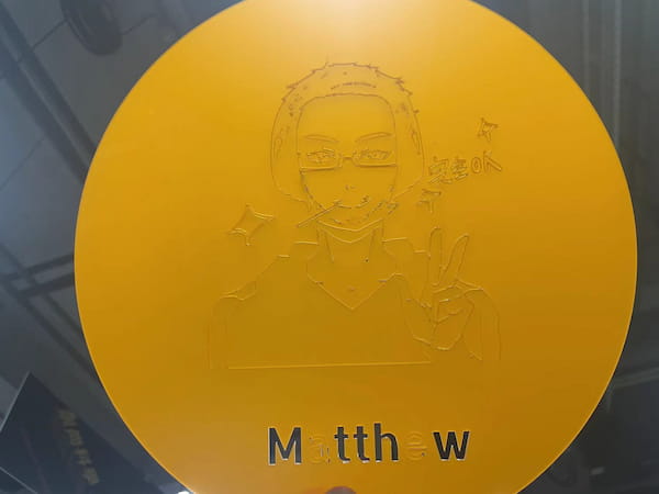
Hero shot of my first 3D design:
The difference between Additive Manufacturing (AM) and Subtractive Manufacturing
Updated on 7.2nd, I revisited the difference between Additive Manufacturing and Subtractive Manufacturing. Then I want to make a spring-like module, and this module does not recommend using Subtractive Manufacturing. For knowing it better, I asked GPT:
Additive Manufacturing (AM)
Also known as 3D printing, additive manufacturing involves building an object layer by layer from a digital model. This process is typically used for creating complex geometries that would be difficult or impossible to achieve with traditional manufacturing methods. If you choose to create your spring-type module using a method like 3D printing metal or plastic, then it would be considered additive manufacturing. This process is beneficial for:
- Prototyping novel spring designs
- Producing complex geometries with internal structures
- Customizing springs for specific applications
Subtractive Manufacturing
Subtractive manufacturing involves starting with a block of material and removing material to shape the final product. This is traditionally done through methods such as milling, turning, or grinding. If your spring-type module is manufactured by starting with a metal rod or sheet and then cutting, carving, or machining it into the desired spring shape, it would be considered subtractive manufacturing. Subtractive manufacturing is typically used for:
- Producing high-strength components
- Utilizing materials that are not suitable for additive manufacturing
- Achieving high precision and surface finish
Conclusion
To sum up, I will design a 3D-printed helical spring with integrated hooks can be used in lightweight applications where a small degree of force absorption is needed. I am going to make one with hexagons on the front and back.
Another module design and 3D printing
Reference by How to 3D Model Threads in OnShape, I will design a spring with integrated features.
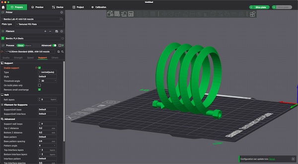
Design on the Onshape:
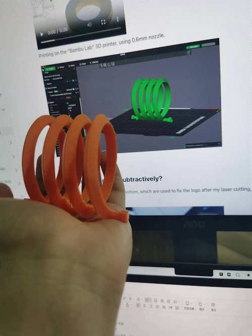
Printing on the "Bambu Lab" 3D printer, using 0.6mm nozzle.
Final look:
Why can’t it be made subtractively?
By integrating features directly into the design of the spring, I can enhance functionality while leveraging the flexibility and capabilities of additive manufacturing to create more sophisticated, tailored, and ready-to-use components.
This is eliminating the need for additional components or assembly steps.
3D scanner using
I am using Luma AI to do the 3D scanning, it is a web-based multimodal AI, so powerful that it utilize Generative AI to enabling converting images or videos into 3D models. It provides models as well.
The knowledge about 3D scanning
The principle behind 3D scanning using images or videos is called photogrammetry. Photogrammetry is the science of making measurements from photographs or images, especially for recovering the exact positions of surface points in three-dimensional space.
reference by 3DSCANEXPERT
Here are the steps for photogrammetry, generated by GPT:
- Image Acquisition: Multiple overlapping images or video frames of the object are captured from different angles. The images should have sufficient overlap (usually 60-80%) to allow the software to identify common points between them.
- Feature Detection: The software analyzes each image and identifies distinct features or points (known as key points or tie points) that are common across multiple images.
- Feature Matching: The software then matches these features across the images, establishing correspondences between the same points in different images.
- Camera Calibration: Using the matched features and the known camera positions (if available), the software calculates the camera's intrinsic properties (focal length, distortion, etc.) and extrinsic properties (position and orientation) for each image.
- Triangulation: With the camera properties and feature matches, the software triangulates the 3D positions of the matched points, creating a sparse point cloud that represents the object's structure.
- Dense Point Cloud Generation: The software then uses the sparse point cloud and camera information to generate a dense point cloud by calculating the depth information for each pixel in the images.
- Mesh Generation: The dense point cloud is converted into a polygon mesh, typically a triangular mesh, which represents the object's surface.
- Texture Mapping: The original images are projected onto the mesh to create a textured 3D model that closely resembles the real object.
The knowledge about Luma AI
Luma AI is a company that provides AI-powered 3D scanning solutions, enables and enhances the photogrammetry process through various techniques and technologies.
It enables and enhances the 3D scanning process using images or videos by leveraging AI and deep learning techniques.
It guides users on optimal image acquisition, employs advanced algorithms for accurate feature detection and matching, automates camera calibration, applies AI optimization for triangulation and dense point cloud generation, creates clean and efficient meshes, and optimizes texture mapping. Additionally, Luma AI offers AI-powered features such as automated object segmentation, semantic understanding, and quality assessment to further streamline and improve the 3D scanning workflow.
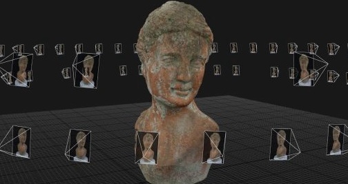
3D scanning on Luma AI
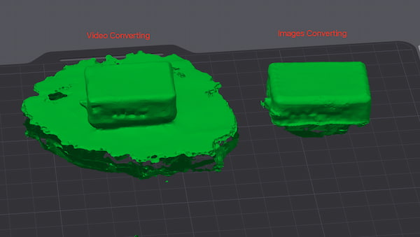
There are some reuqirements for convering:
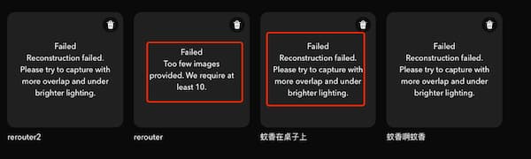
These errors indicate that there is something wrong with the picture or video I uploaded (poor lighting or too little, too short).
I will try both video converting:
and images convering(.zip)
And after serval times failure, these are the final output(it presents embedded html code so everyone can integrate them on their website):
images converting:
video converting:
The final thing is that it supports these files output:
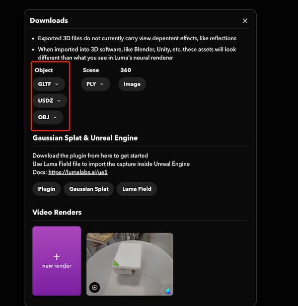
And I open them as OBJ file:
It looks interesting, I will try different angles to present them and see how's different.