Week 4 - Embedded programming

Assignments | Week 4 | Computer-controlled Cutting
Group assignment
- Compare the performance and development workflows for other architectures
- Document your work to the group work page and reflect on your individual page what you learned
Individual assignments
- Browse through the datasheet for your microcontroller
- Program a microcontroller development board to interact and communicate
Learning outcomes (What should be achieved)
- Identify relevant information in a microcontroller datasheet.
- Implement programming protocols.
Table of content
Group Assignments
If you’re just starting out with embedded programming and find the concept a bit unclear in your mind, you’re not alone. I have documented the concepts to know before programming a microcontroller, and compared 2 different microcontrollers: one from ESP and another from ARM.
If you are an advaced programmer, and curious to know how to work with then the work of Clara on
Individual Assignments
1. Browse through the datasheet for your microcontroller
Attiny 1614 Datasheet
In a datasheet of microcontroller, we can find informations about a serie of microcontrollers.
Datasheet ATtiny1614/1616/1617 tinyAVR® 1-series
Features
In Features we can find an overview of the microcontroller’s key capabilities, functions, and performance characteristics:
- CPU
- Memories
- System
- Peripherals
- I/O and Packages
- Temperature Ranges
- Speed Grades
In this programming week, I was focused on several pages.
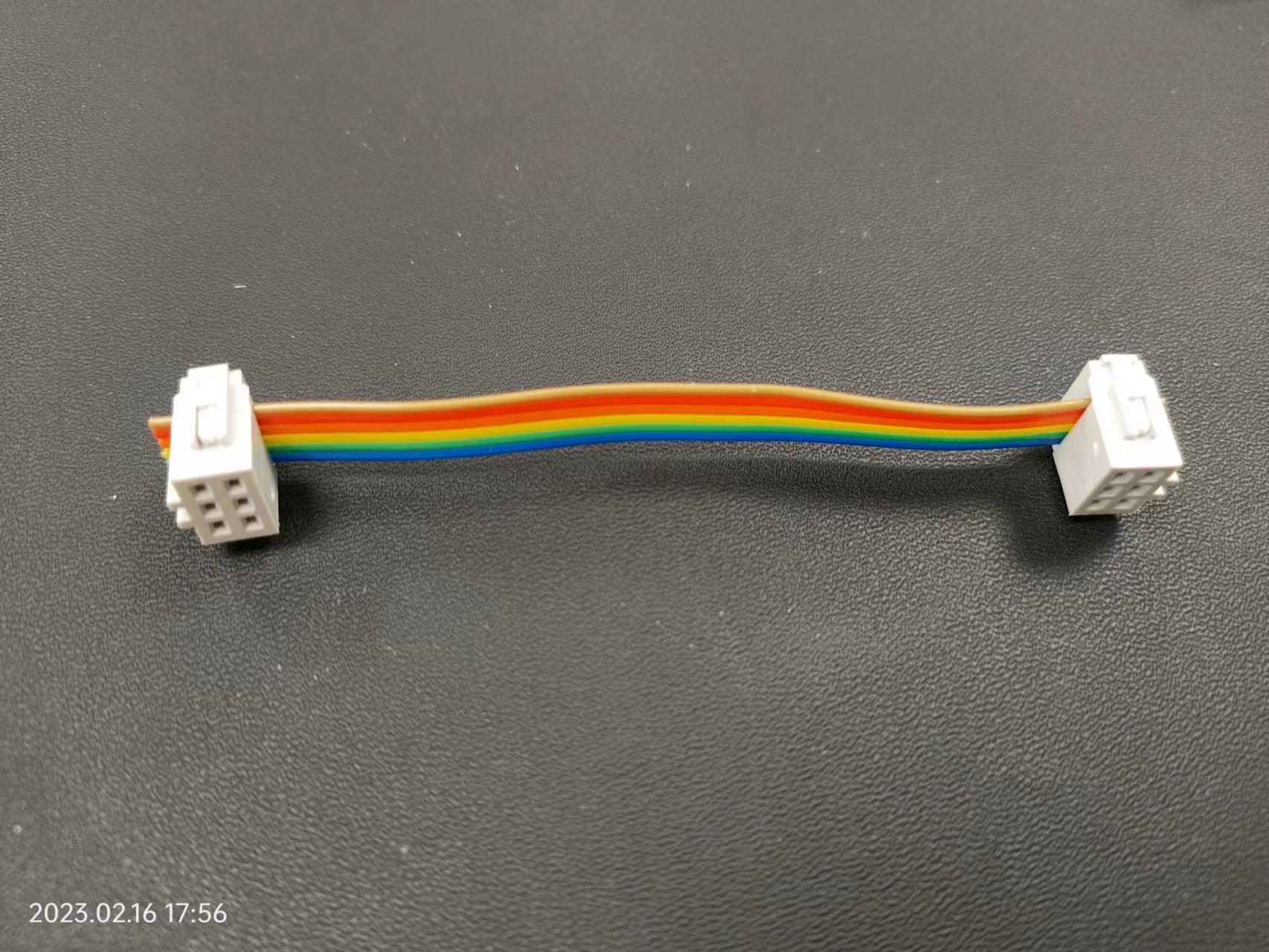
Pinout and package information
In this section we can find information about the physical characteristics of the microcontroller, such as the number and function of its pins, the size and type of the package, and the pin configuration.
Memory architecture
Where we can find information about the microcontroller’s memory architecture, such as the size and type of its flash memory, EEPROM memory, and SRAM, as well as details about memory organization and addressing.

Vocabulary and definitions
Digital pins Digital pins are the physical pins on a microcontroller that are used to communicate with external devices. These pins can be set to either input or output mode, and their state (high or low) can be read or set by the microcontroller.
The primary purpose of digital pins is to provide a simple interface for the microcontroller to interact with external devices, such as sensors, actuators, and displays. By manipulating the state of these pins, the microcontroller can send and receive data to and from these devices.
Registers Registers are special-purpose memory locations that are used to configure and control the behavior of the microcontroller. Registers are used to set up the microcontroller’s operating mode, such as configuring the clock speed, setting up interrupts, and controlling the power management features of the device. Registers are also used to configure the behavior of the digital pins, such as setting the input/output mode, enabling or disabling pull-up resistors, and configuring other digital I/O settings.
The primary purpose of registers is to provide a way for the microcontroller to control and configure its own internal behavior and the behavior of its digital I/O pins.
UPDI(Unified Program and Debug Interface)
communication protocol of Attiny’s microcontroller.
Chip Packaging
The packaging of a chip
SOIC or SO followed by the number of pins (= Small Outline Integrated Circuit)
2. Embedded programming
Requierments
- A development board + wires
- A computer with internet for research and datasheet
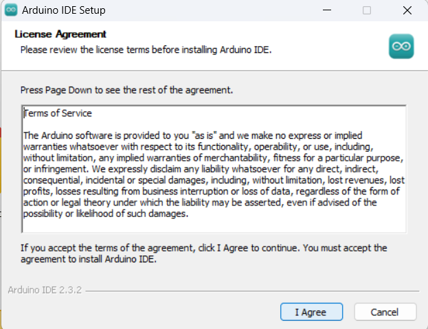
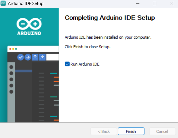
- Install Arduino IDE
- Install library
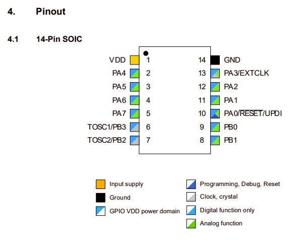
I’m using the board that Stephane created for the Fab’Academy 2023 bootcamp
-
Features:
- 1 Attiny 1614 (microcontroller)
- 3 LED
- 1 Button
- 1 USB-C Port
- 1 Capacitor
- 6 Resistors
- 1 Row pin header
- 2 Rows pin header
During the student bootcamp week, our instructor gave us a board with USB-C Port and asked us to complete this board by soldering the rest of the electronic componants.
-
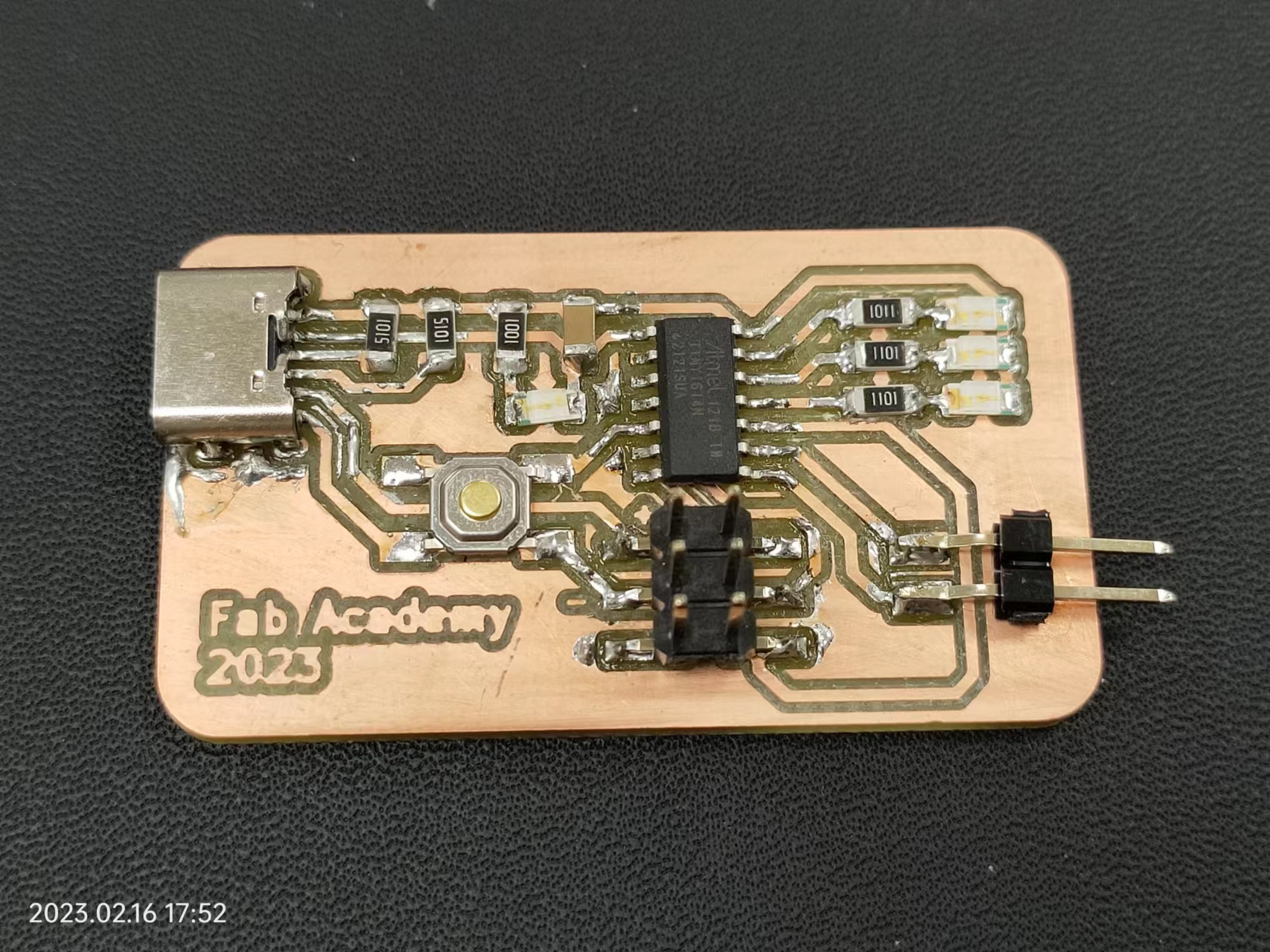
A Programmer
-
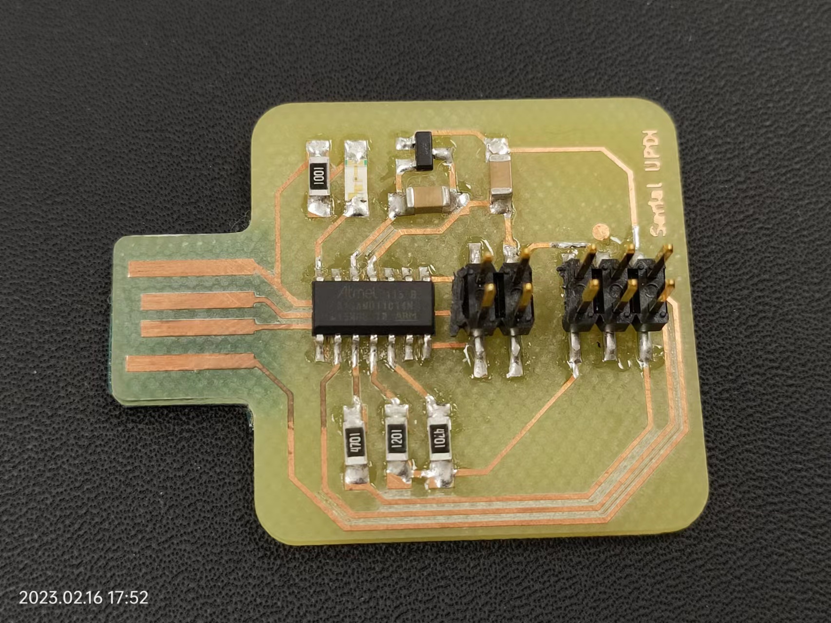
A rainbow wire flat ribbon cable 6 pins
Step by Step installation
I installed Arduino IDE by following the official installation guide.

To add Annity board in Arduino IDE, I followed the documentations below: - “Arduino IDE to program Fab Academy microcontrollers (ATtiny412, ATtiny1614, ATtiny3216, ATtiny1624, AVR128DB32, SAMD11C, D11D, D21E, D51)” : https://gitlabsu.sorbonne-universite.fr/fablabsu/fabacademy/arduino-ide-setup - https://github.com/SpenceKonde/ATTinyCore
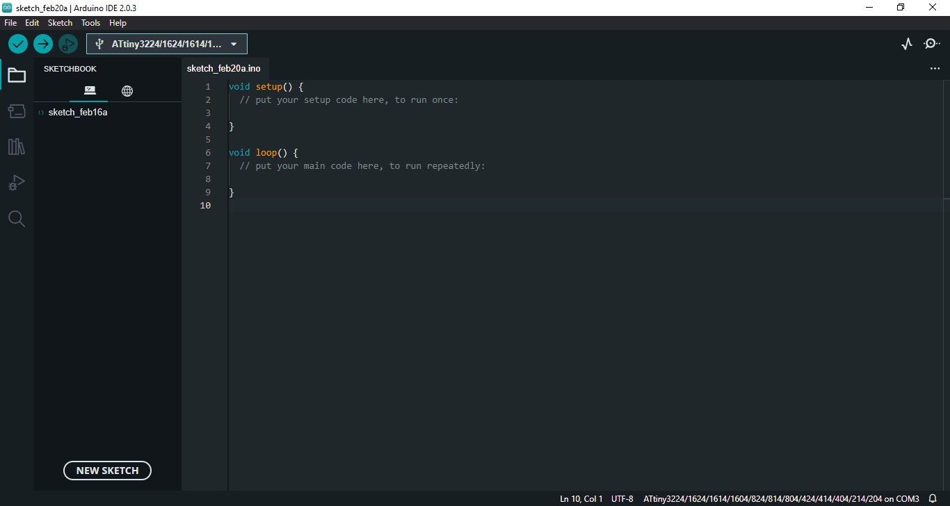
I opened File>Preferences>
List
ATtiny2313 ATtiny4313 ATtiny24 ATtiny44 ATtiny84 ATtiny25 ATtiny45 ATtiny85 ATtiny261 ATtiny461 ATtiny861 ATtiny87 ATtiny167 ATtiny48 ATtiny88
The board interacts with 3 LED and a push button and communicate via USB with the computer and via Serial with local devices(LED and button).
2.1 Understand the principles of coding
I had programming in C course before Fab’academy. So reading and understanding the code in C wasn’t difficult for me. But still, I had to browse the Arduino documentation because I was unfamiliar with its functions. Here is some important functions:
Arduino’s functions
Arduino's functions documentation
pinMode(PIN, MODE);
Parameters:
- PIN: digital pin of arduino
- MODE: INPUT, OUTPUT, or INPUT_PULLUP
digitalWrite(PIN, VALUE);
Parameters:
- PIN: Arduino pin number
- VALUE:
HIGHorLOW
Sources:
2.2 Blink a LED 
Our instructor Stephane provides us his version of code
#define LED 2
#define BIN 0

void setup() {
    pinMode(LED, OUTPUT);
    pinMode(BIN, INPUT_PULLUP);
}

void loop() {
    digitalWrite(LED, HIGH);
    delay(100);
    digitalWrite(LED, LOW);
    delay(100);
}
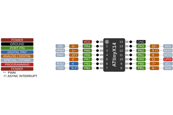
Before my modifications, it does nothing. Because the PIN of the LED on his board wasn’t the same as mine.
Attiny 1614 PINOUT This image helped me to find the digital pin and the port pin that I need
Source:
#define LED 10 // -> PIN 10 I found the right PIN on my board
#define BTN 0

void setup() {
    pinMode(LED, OUTPUT);
    pinMode(BTN, INPUT_PULLUP);
}

void loop() {
    digitalWrite(LED, HIGH);
    delay(100);
    digitalWrite(LED, LOW);
    delay(100);
}
I modified the value of the LED’s PIN, and it works! This code makes one of the LED twinkle
How does it work? To control an LED connected to an Input/Output pin on a development board, the microcontroller would first need to: 1. Configure the I/O pin as an output pin by setting the appropriate bits in the associated I/O register. 2. To turn the LED on or off, the microcontroller would write a logical high or low value to the I/O register associated with the pin, respectively.
2.2 Working with I/O Registers: LED display
Whats is I/O registers? Acording to 6.8 I/O Memory of the Attiny 1614’s datasheet,

I/O registers are a type of memory in microcontrollers. These registers are used to control and configure the behavior of these external devices, as well as to read and write data from and to them.
PORTA.DIR
void setup() {
  PORTA.DIR |= PIN3_bm;
  PORTA.DIR |= PIN2_bm;
  PORTA.DIR |= PIN1_bm;
}

void loop() {
  PORTA.OUT = PIN3_bm;
  delay(500);

  PORTA.OUT = PIN1_bm;
  delay(500);

  PORTA.OUT = PIN2_bm;
  delay(500);
}
2.3 Connect button
I found the code of this tutorial interesting so I took the code and modified it.
Button tutorial: - https://roboticsbackend.com/arduino-push-button-tutorial/
Code
#define BUTTON_PIN 3
int counter=0;

void setup()
{
  Serial.begin(9600);
  pinMode(BUTTON_PIN, INPUT_PULLUP);

}

void loop()
{
  byte buttonState = digitalRead(BUTTON_PIN);

  if (buttonState == LOW) {
      counter++;
      Serial.print("Button is pressed ");
      Serial.print(counter);
      Serial.println("times");
  }
  delay(10);
}
Video before debouncing the button
Bug
The program count multiple false button presses
2.4 Button State debouncing
In order to fix this issue, Stephane reccomanded the ButtonStates library.
In Arduino IDE :
1. Add library to Arduino IDE - Sketch Include library add .ZIP library Select the zip file downloaded
2. Use the library - Sketch Include library Click ButtonStates in the contributed library section
After debouncing
#include <ButtonStates.h>

#define BUTTON_PIN 3

ButtonStates button(BUTTON_PIN);

void setup()
{
  PORTA.DIR |= PIN3_bm;
  PORTA.DIR |= PIN2_bm;
  PORTA.DIR |= PIN1_bm;

  PORTA.OUTTGL |= PIN3_bm || PIN2_bm || PIN1_bm;
  delay(100);
  PORTA.OUTTGL |= PIN3_bm || PIN2_bm || PIN1_bm;
  delay(100);
  PORTA.OUTTGL |= PIN3_bm || PIN2_bm || PIN1_bm;
  delay(100);
}

void loop()
{
  Serial.print("");
  int userAction = button.triggerLong();


  if (userAction == 1){
    PORTA.OUTTGL = PIN3_bm;
    Serial.print("blue light");
  }
  if (userAction == 2){
    PORTA.OUTTGL = PIN2_bm;
    Serial.print("green light");
  }
  if (userAction == 3){
    PORTA.OUTTGL = PIN1_bm;
    Serial.print("white light");
  }

  delay(5);
}
2.5 Final program
3. Ressources that helped me
Stephane’s documentation on how to setup Arduino’s IDE - https://gitlabsu.sorbonne-universite.fr/fablabsu/fabacademy/arduino-ide-setup
Kim’s documentation on embedded programming week - http://fabacademy.org/2020/labs/seoulinnovation/students/hyunho-kim/week8.html
A pdf that explains how to use the microcontroller’s pins:
Understand Arduino’s pinMode
Conclusion
This week has been frustrating and my mind was full with questions about the topic of this week, such as
Why is the programming week about microcontroller ?