Week 10 - Mechanical and machine design

Assignments | Week 10 | Computer-controlled machining
Mechanical Design (part 1 of 2)
Group assignment
- Design a machine that includes mechanism + actuation + automation + application
- Build the mechanical parts and operate it manually.
- Document the group project
Individual assignment
- Document your individual contribution.
Machine Design (part 2 of 2)
Group assignment
- Actuate and automate your machine.
- Document the group project
Individual assignment
- Document your individual contribution.
Learning outcomes
- Work and communicate effectively in a team and independently
- Design, plan and build a system
- Analyse and solve technical problems
- Recognise opportunities for improvements in the design
Group documentation and video
Plotter’s X axis
The X-axis of a plotter is responsible for controlling the movement of the pen or tool holder along the horizontal axis of the drawing surface.
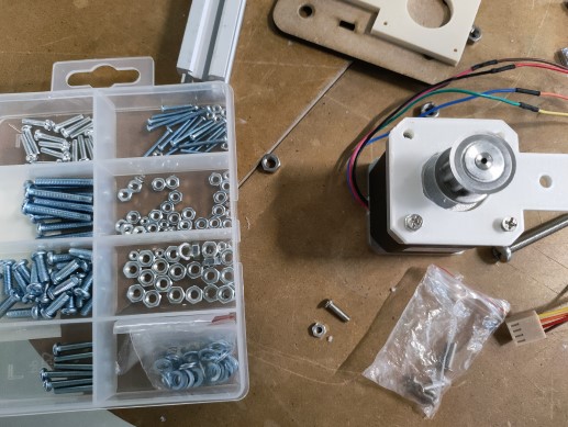
Materials for the plotter’s frame:
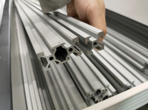
- Profile
- Stepper motor
- Belt
- Pulley
- Screws
- Washers
- Nuts
During the team meeting, we were browsing images of plotter to familiarise ourselves with different kind of plotter. Then we decided a design.
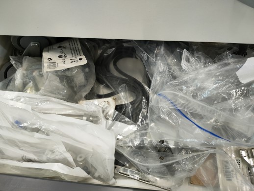
After that, our fab manager shows us the materials we have in Fablab Sorbonne.


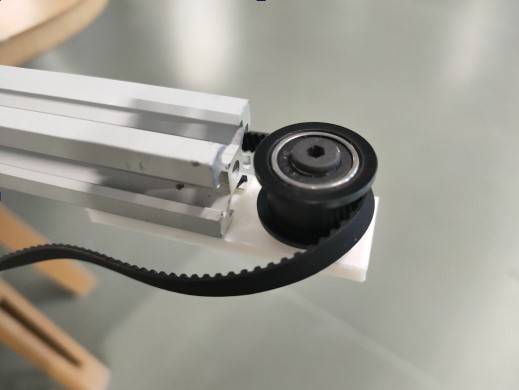
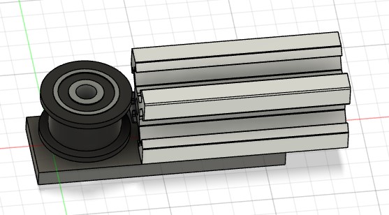
Slowly, I took the belt and combined with the profile. I guess that this action activated some part of my brain for spatial reasoning and mentally manipulating objects.
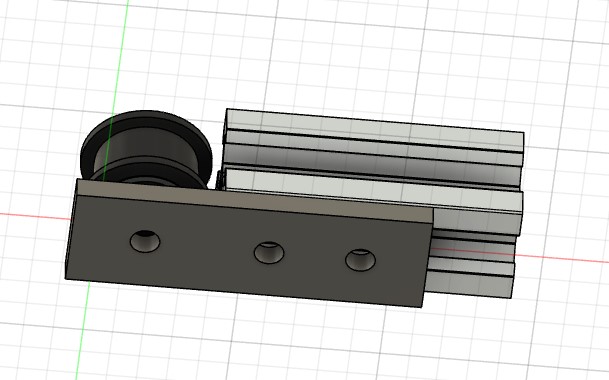
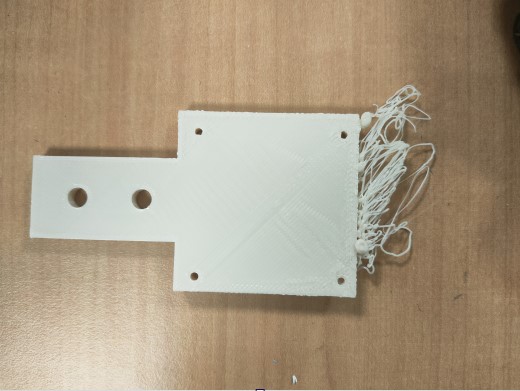
I realized what I need to create for the X-axis: supports for fixing the pulley and the stepper motor.
Determine the dimensions
Here is the website for 3D model of the materials that we have:
I imported some 3D models in our Fusion team workspace. And tryed to create a support on fusion. All went well. At least, before I measured the dimension of the imported stepper motor’s 3D model… Desperation! I found that the dimension of the profile isn’t the same as the real-size measured by a caliper.
| Stepper Motor | Length |
|---|---|
| 3D model | 41 mm |
| Reality | 42.1 mm |
So I resized the support created
Create CAD 3D model : Fusion 360
| Tools used: | Sketch | Extrude | Hole | Measure |
|---|---|---|---|---|
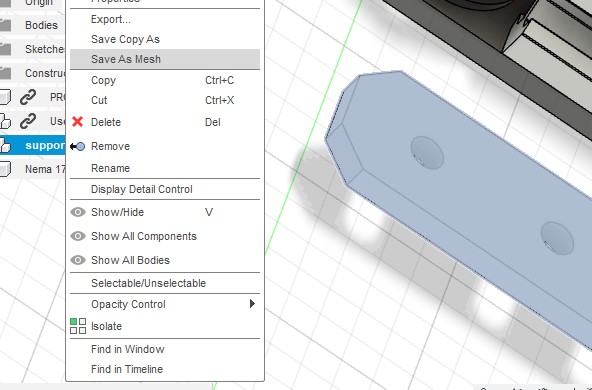
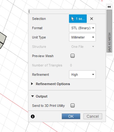
Export the CAD model
Select the component > Save as mesh > Format:STL > OK
Import the model into slicing software: IdeaMaker
| Setting | Value |
|---|---|
| PLA | 1.75mm |
| Quality | High Quality - Pro2 Plus - PLA |
| Layer Height | 0.1mm |
| Shells | 2.0 |
| Infill Density:15% | |
| Generate Support | None |
| Platform Addition | None |
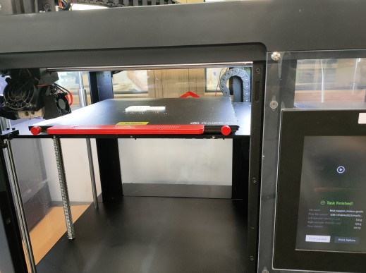
Generate the G-code and load it onto the 3D printer
Some pieces didn’t go well. Because the fan of the 3D printer wasn’t activated.
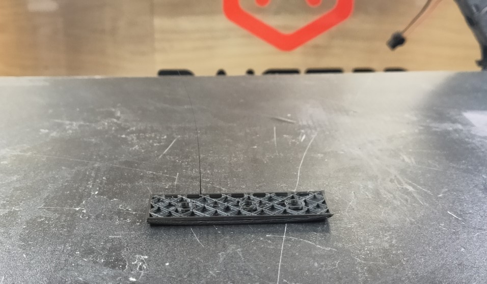
I also found that Standard quality changes the dimension of the final result (expected height: 4mm, final result: 4.2mm). Because this quality setting use 0.2mm of layer height. So it is better to keep the settings of High Quality with 0.1mm of layer height to ensure that the result fits well the components.
| Standard quality | High Quality |
|---|---|
| Layer Height: 0.2mm | Layer Height: 0.1mm |
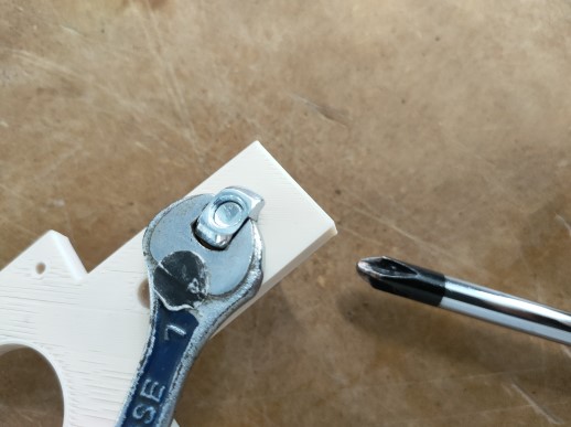
Mount the stepper motor onto the support
Use screws and nuts to attach the stepper motor to the support, making sure it is securely fastened.
Attach the support to the profile
Mounting the t-slots of the support
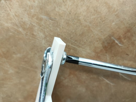
Slide the T-slots of the support onto the T-slots of the profile and tighten the bolts to secure it in place.