5. Electronics production
This week I worked on creating a circuit board usb that I can use to program other circuit boards
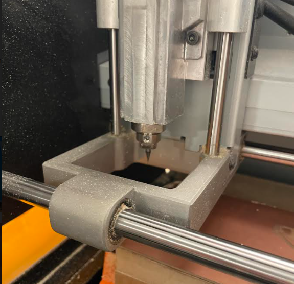
Group Project
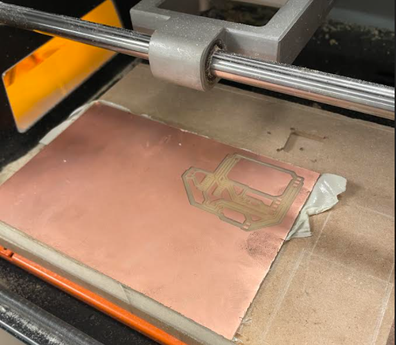
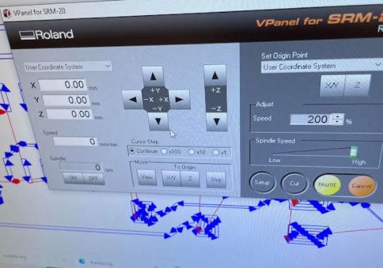
We started by getting our copper plate and taping it down to the platform of our milling machine so that when we engrave/cut our circut board the copper won’t move around and mess up our design. Afterward we opened up our program VPanel that will allow us to communicate from our computer to our machine. The X will move the drill bit from left to right, the Y will move the platform forward and backward, and the Z will move the bit up and down. Before we start we change our drill bit to a 1/64 inch bit to allow us to engrave. In order to engrave the bit needs to be installed and then have it touch the copper plate when that is done we can set the origin point for the Z-axis as well as the X and Y axis.
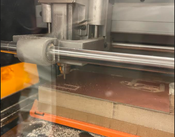
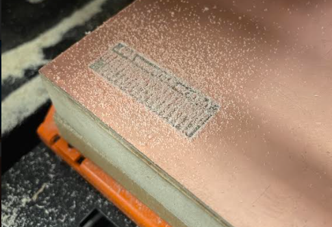
From there we uploaded our test outline file and sent it to the machine being careful to ensure there’s only one file attached. The engraving finished and we then switched the bit to a 1/32 inch bit, set the origin for the Z-axis again for the new bit and then uploaded the cut file to allow us to seperate our circut board from the copper plate.
Process
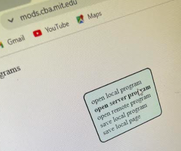
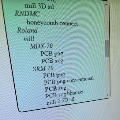
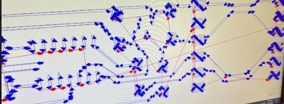
I started this by opening an open server program in the mods website and selected the file type that works for our machine, in this case being the SRM-20.
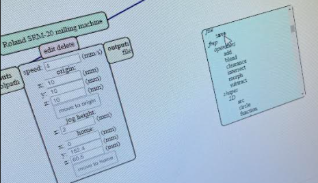
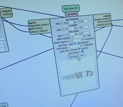
 From there I made a save module and uploaded my SVG file for our engraving and made sure to press the 1/64 option to differentiate it to the outline file. It is important to calculate the tool diameter so that the file will match up correctly to the machine.
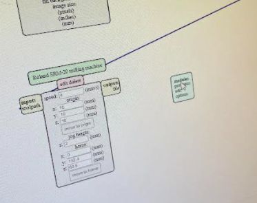
 With that I was able to form the file and upload it to VPanel after mods produced the file. I then set the X and Y axis origin and added the 1/64 bit, set the Z-axis origin, and uploaded it to cut the engraving.
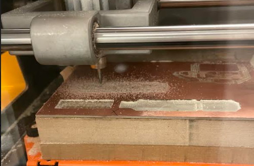
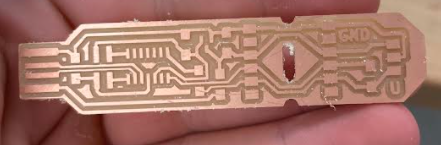
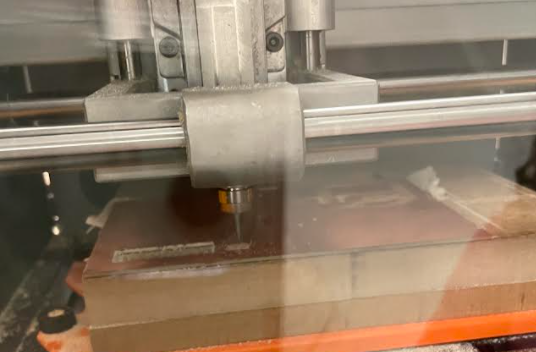 After it finished engraving I did the same process over again but instead of pressing the 1/64 option in Mods I pressed the 1/32. With the circuit fully cut out I realized a slight issue. I had accidentally forgotten to invert the image so the circuit was inside out. I pressed that and fixed the issue after some recutting.

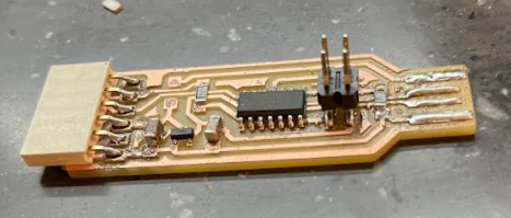
The next step was to solder the pieces needed for my circuit to become a usb. It took me a bit to find a comfortable way to solder, I initially had it set up to a clamp like system, to a vice grip, to inevitably just using the table.
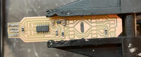
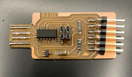
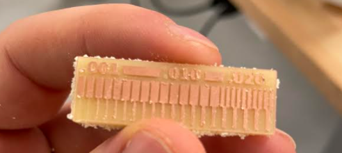
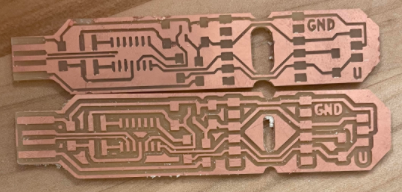
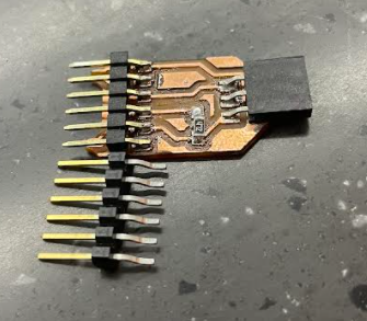
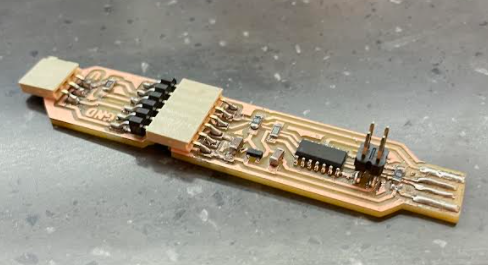
I would then go on to solder my pieces making sure not to accidentally solder a piece incorrectly whether that be by the placement of the piece on the board or its orientation. There were a few pieces I had to cut in order to fit it on the board, notibly I had to cut the board itself because we only had connecting pieces that were too long for the board to let me solder it in together. I compared using the example board where you can see the difference.

After completing my board I tested its ability to connect to my computer as a usb and it failed so I went back to check any connection issues. I had an example board on hand so I tested that and it would connect either by itself or with the back connecting piece. I tested the example usb with my back piece and it failed to connect so I knew there was an issue there and tested the electrical connections until I found the issue.
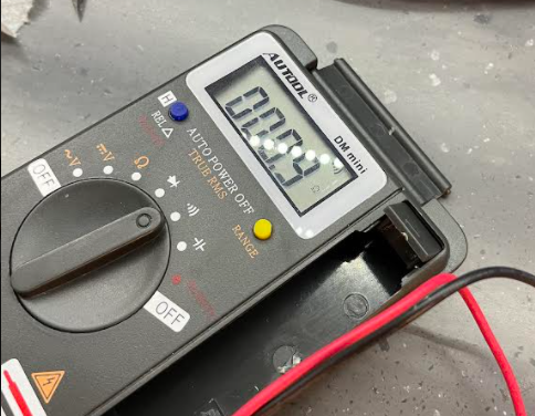
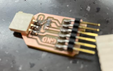
I took apart the piece I needed to re-solder and just reoriented it to connect better. The back piece I tested again with the example USB and my own USB and it succeeded with the example and not mine. So I went back to potential spots to resolder and I essentially re-soldered 50% of the front piece of the board.
My circuit seemingly had passed the smoke test with no issue but unfortunately due to a lack of time due to my family needing help over the weekend I only had Monday and Tuesday night to work on my circuit board with most of Tuesday being used to attempt to fix the issues with my board. I will go back and fix this in tandem with my assignment next week. In hindsight I probably missed the programming step to allow my board to program others but I lacked the time after being in the lab for hours and it closing.
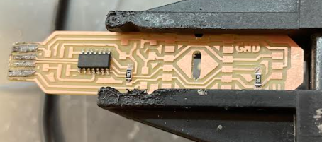
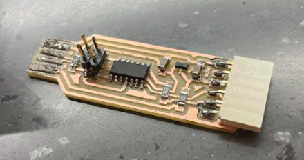
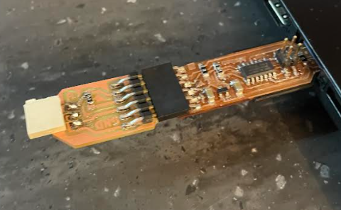
Much later into the year we are given a new file to work with that should be more effective than the previous so I milled out the circut board and soldered the correct material.
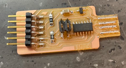 The next board I made failed the smoke test again so I had to make yet another board.
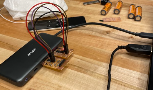
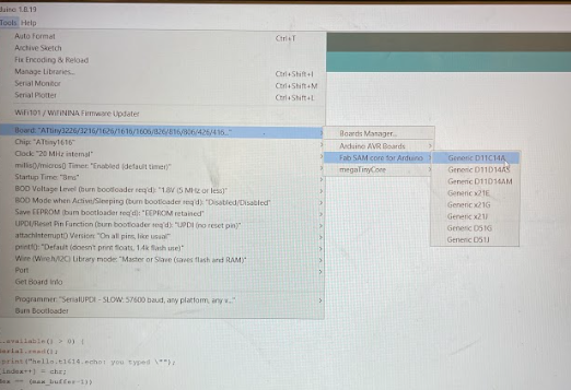
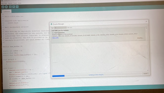
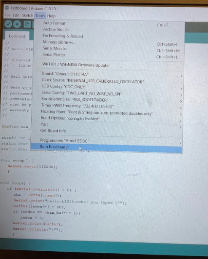
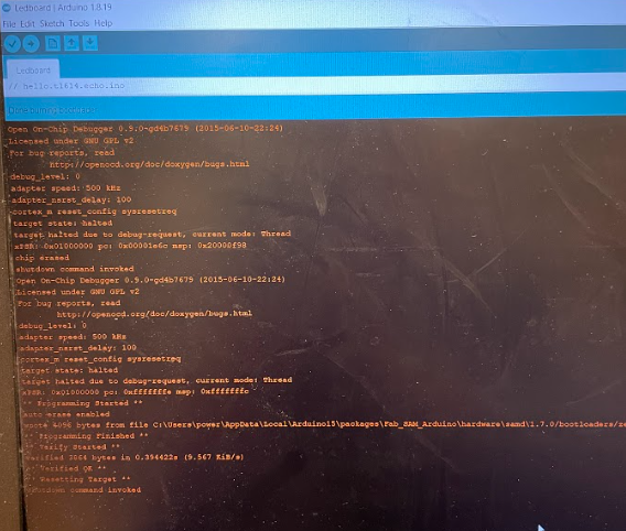
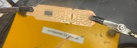
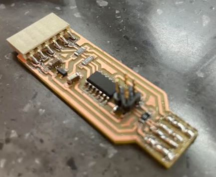
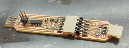
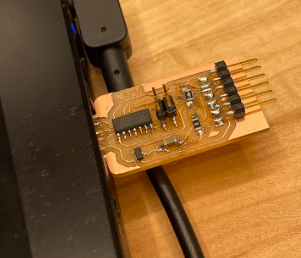 Thankfully the next attempt finally worked. The board successfully passed the smoke test and was recognized as a usb. From here I grabbed a programmer and connected it to my board and my usb port with an adapter. Having the adapter and my board plugged into my computer my arduino was able to recognize the boards so I could properly set up the options needed to burn my bootloader. The bootloader burnt successfully on the first try, finishing my long journey for this week.