3. Computer Aided design
This week I worked to learn or better myself in CAD software in order to design my final project or a portion of the project both 2D and 3D.
Weekly Goal
- figure out what I would like to design
- better my skills in CAD programs I’m not as skilled in
- have the designs be much more clear than before
Useful links
Process
For this week I had wanted to use a program that I am not sufficently proficent in so I had chosen Adobe Illustrator and Fusion 360. I am rather familair with Adobe products but I have an affinity for photo shop so my illustator skills are lacking. Fusion 360 I have used before but I am a novice in terms of 3D design programs.
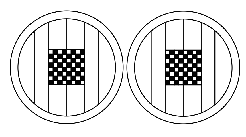
I started by transferring my intial sketch into Adobe Illustrator by opening the file with the program. I then used the elipse tool to create the base of what would be the bird’s eye view of the table .
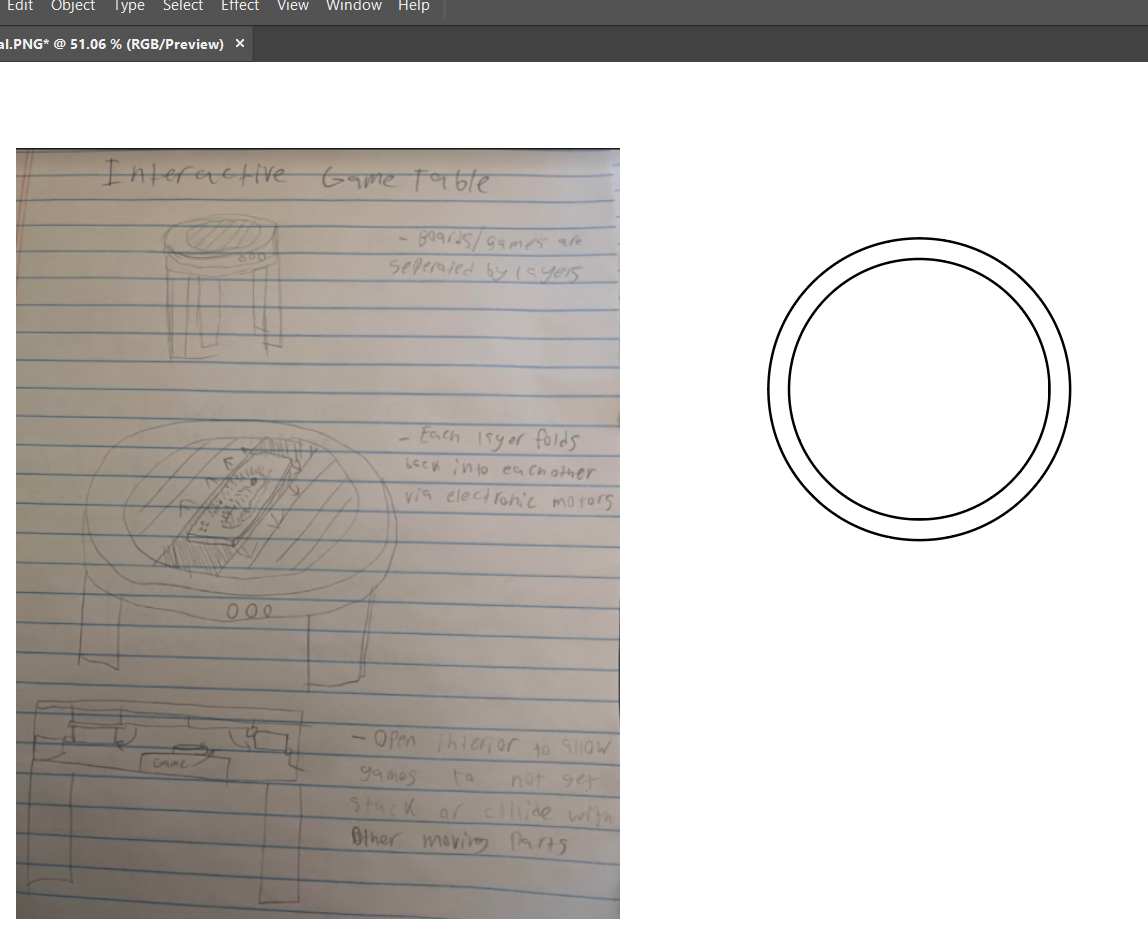

The next step I did was utilise the line segiment tool and the curvature tool to create the side view of the table. Using the line segiment tool I would divide the table top into sections that represents the different plates of wood that will shift around after the electronics are implimented.

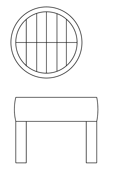
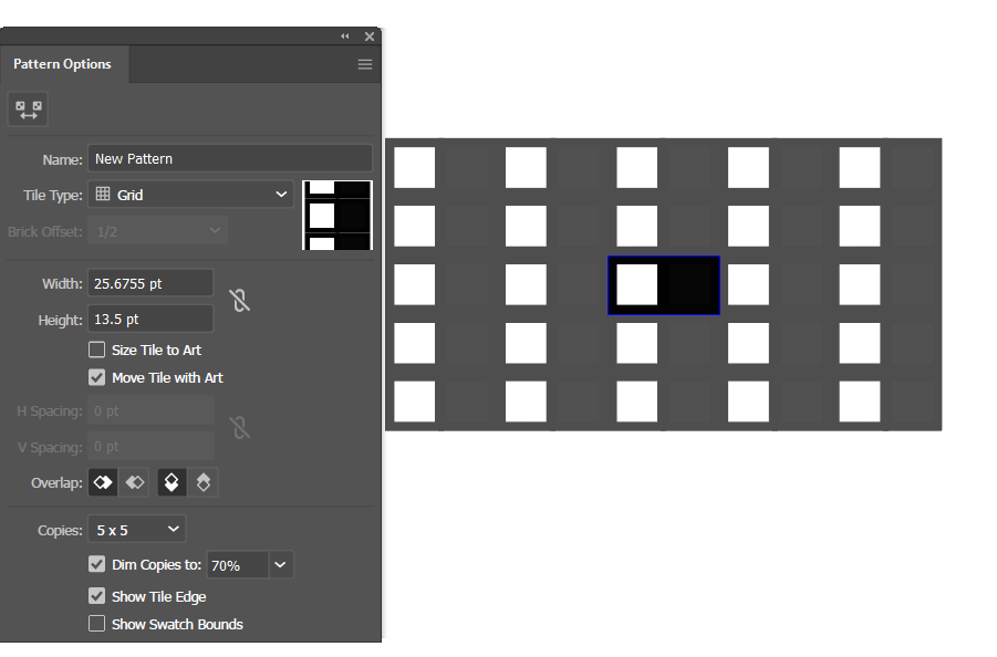
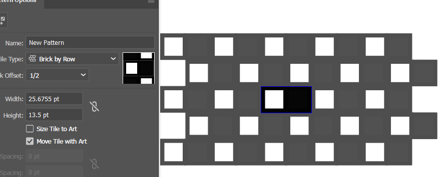
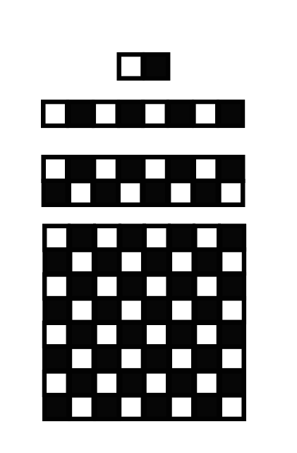
Since this will be a game table I decided to create a checker board pattern that one would use for a game such as chess or checkers. Initially I took 2 squares with the rectangle tool and tested the pattern tool but each designs I created hadn’t matched up to what I anticipated. So I had to do things manually first creating the line for each square and a varitation that I would switch in and out.

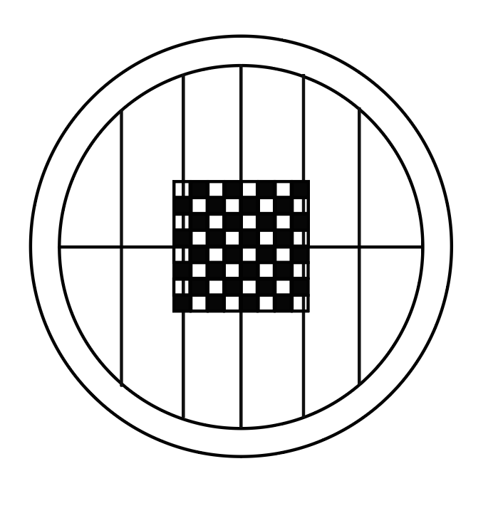
The design then needed to be placed onto the board with the middle lines being used as a reference point to center the board. The board didn’t quite fit so there was a slight adjustment in postitoning.

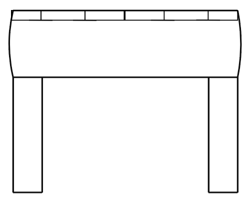
With the table top designed I copied the current design in order to make an open table variation. This version is a simple example of how the table might look with the first row of paneling pulled in with ample open space for whatever game is decided to be placed there.

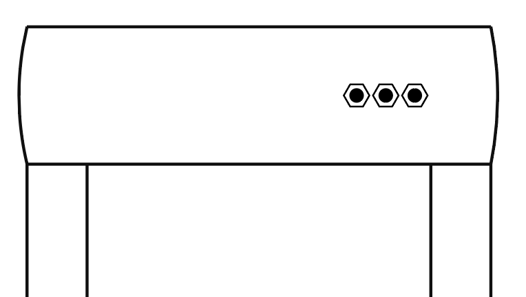
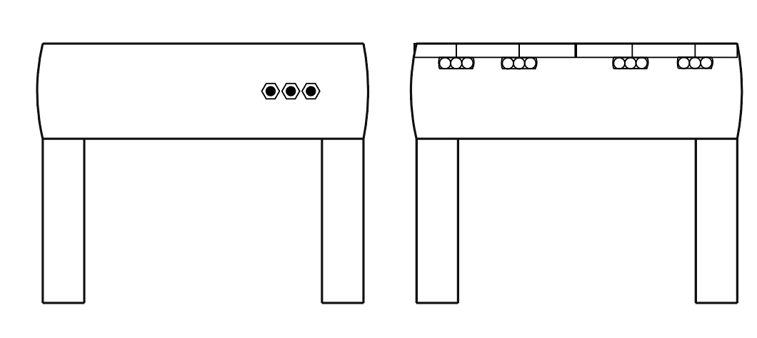
The next step was to work on the side view of the table including some design of the internal structure of the table. First I just made a simple button design with the polygon tool to would communicate to the internal electronics. Now with that done I can work on the internal design of the table with a blank copy of the side view.

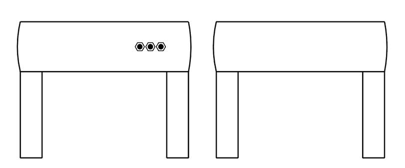
First I just added a simple indicator of the seperate boards or plates of the table top. I then followed up by creating a simple design of a conveyor belt like object that is meant to pull back the board it is connected to via the corrosponding button. The design was then added to the mock up design in order to present some idea of what it could look like.
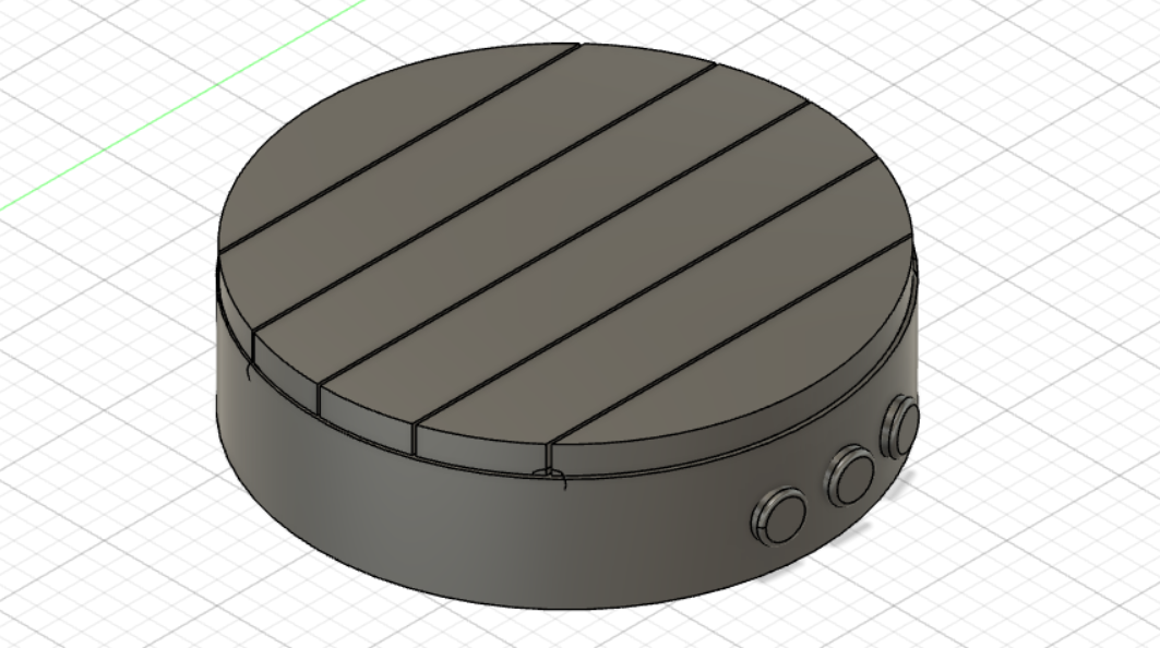
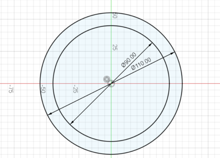
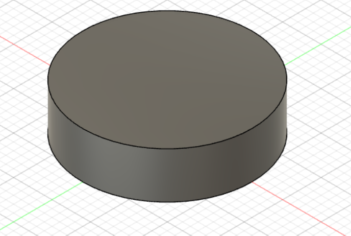
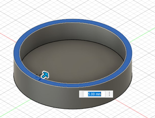
Now onto Fusion 360. I used the sketch tool to make two basic circles just as I had in illustrator but I follwed it up by pressing e to use the extrude tool which essentially allowed my sketch to turn 3-dimensional pushing it up 25.00 millimeters. Afterward I would look into the tool kit to find the shell tool that allowed me to hollow out the interior of block.
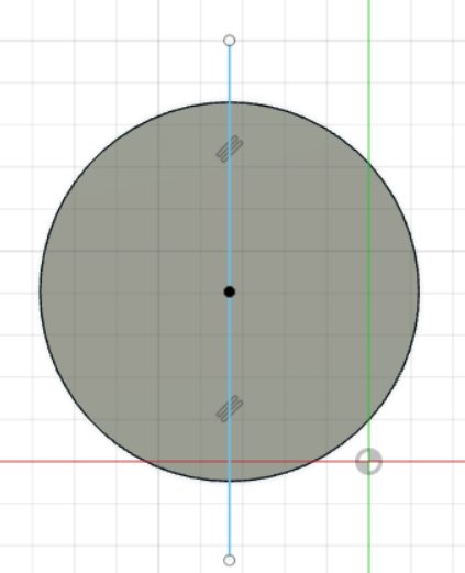
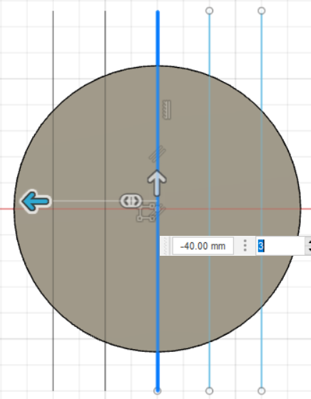
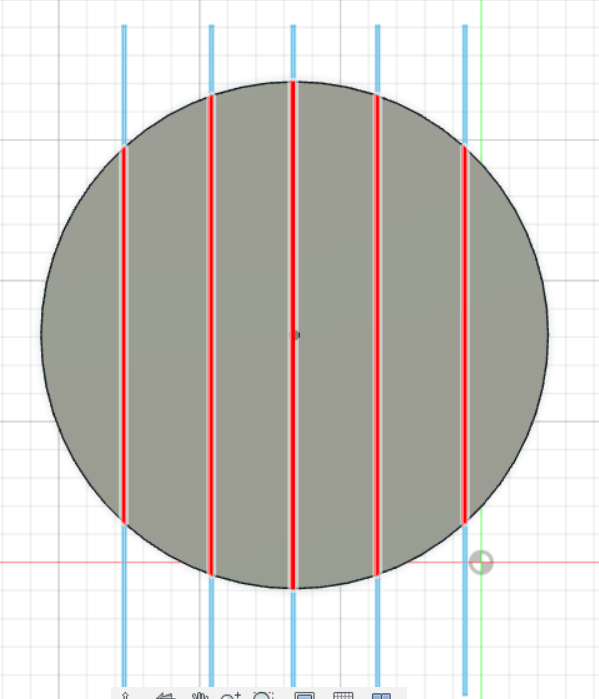
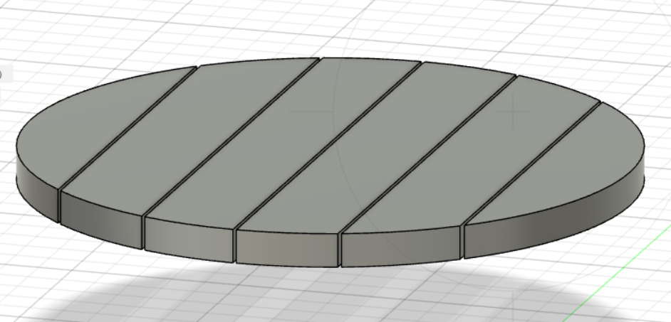
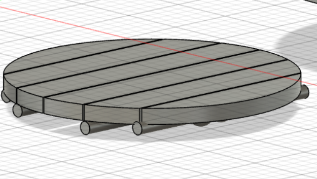
Following this I had again made a circle sketch but this time for the panel that would top the table. I extruded the sketch and followed it up with a sketch of a line in order to break up the panel. Utilising the tutorial in the helpul link section of this page I used the rectangle pattern tool to evenly space out the paneling followed up by an offset tool and line tool to cut out the paneling. The offset tool would allow me to make rectangles that I would then extrude to get the intended result.
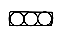
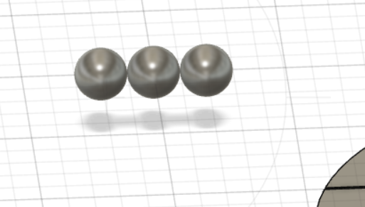
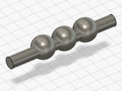
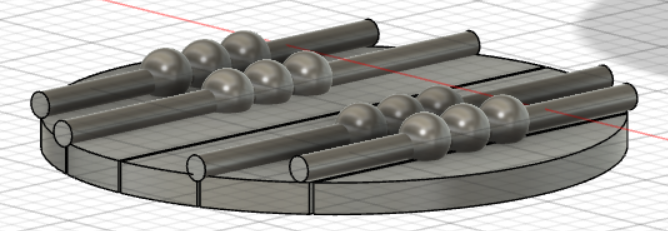
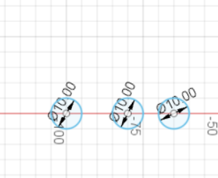
The next step I went into was creating the “conveyor belt” 3d design. I started with creating 3 10mm sized spheres. I lined those up side by side and created a cylinder that would but put inbetween the 3 spheres. The concept here is the cylinder will get a signal from the electronics that will rotate the individual plates so that they may go back and forth under one another. I then added the top of the table to the base.
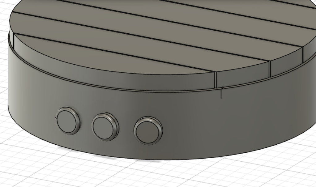
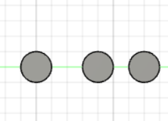
After creating the “conveyor belt” I had to create mock buttons that would be used to interact with the “conveyor belts”. it was a simple matter I made 3 sketch cirlces, extruded them by 5 millimeter and then I utilised the fillet tool and changed the shape to what it is now.
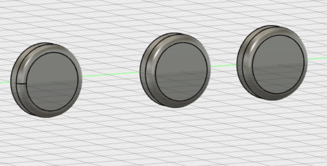
The buttons would then be added to the table top making the basic 3D design to be complete.