14. Networking and communications
Assignment
This week’s assignment was to design, build and connect wired/wireless nodes with network or bus addresses.
To form a kind of simple communication between two PCB boards,I designed a PCB board with a switch button in a such way that I can press the Push Button on the first board and turn the LED ON of the second board.
The first board with push button is the master while the second board with LED is the slave. i.e Master to slave communication.
Master to slave communication
A model of communication where one device has an undirectional control over one or more devices. the master device acts as controller whereas the slave device acts as being controlled.
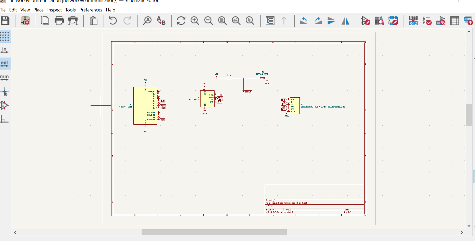
The following is the schematic design of my pcb that acts as the master. the slave one i have decided to use Arduino Uno.
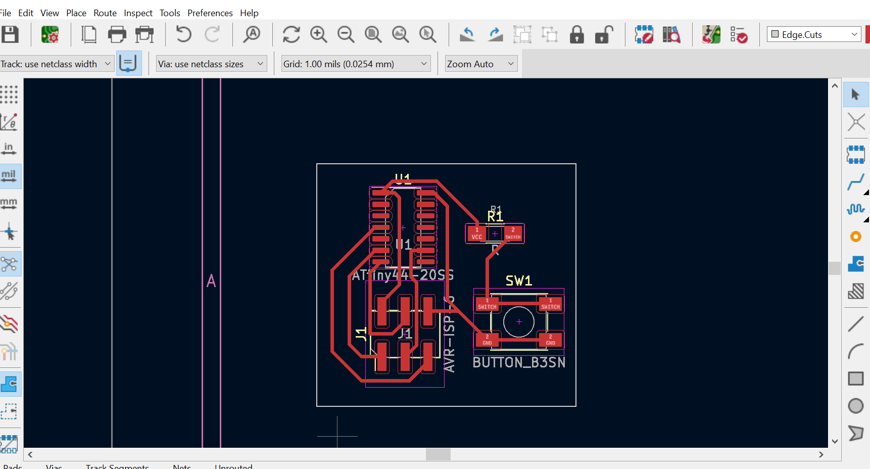
this is the PCb after assigning footprints
 After assigning footprints and make routing, I plotted and save it as SVG file and then converts it in PNG in GIMP.
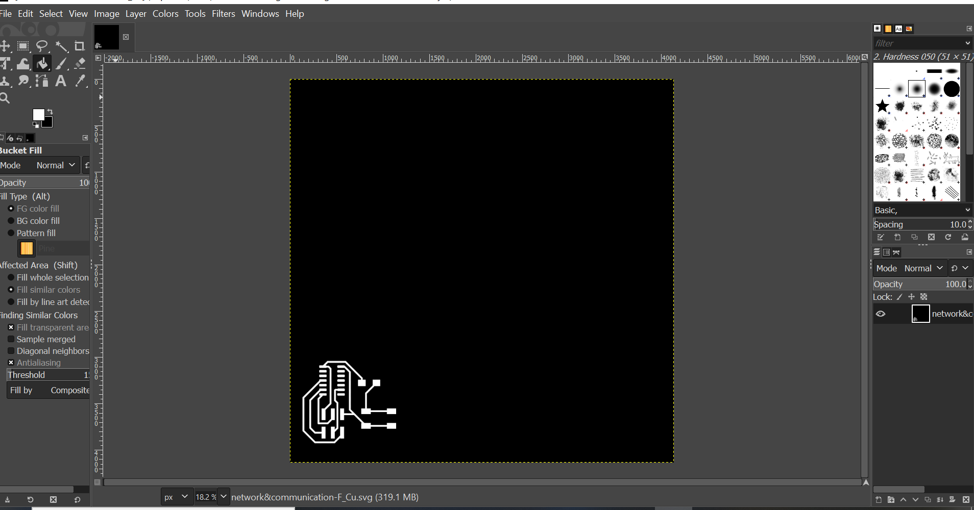
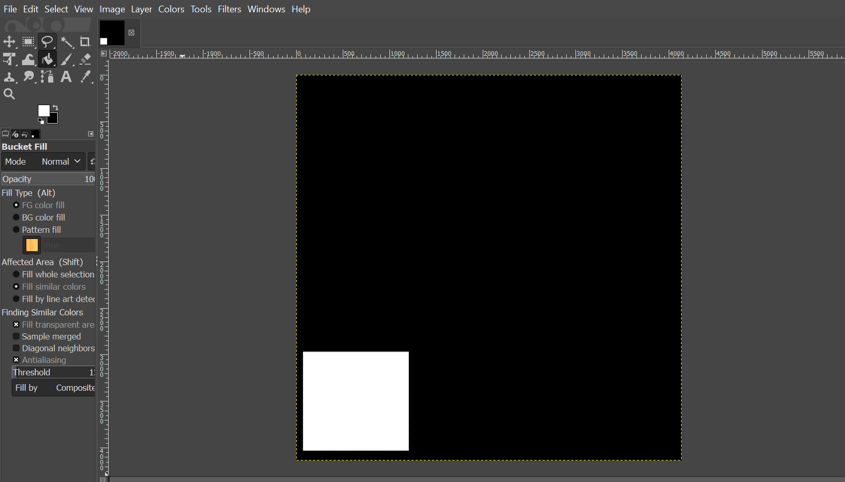
edge-cuts png image to be loaded in mods to generate rml files that the Roland machine can understand .

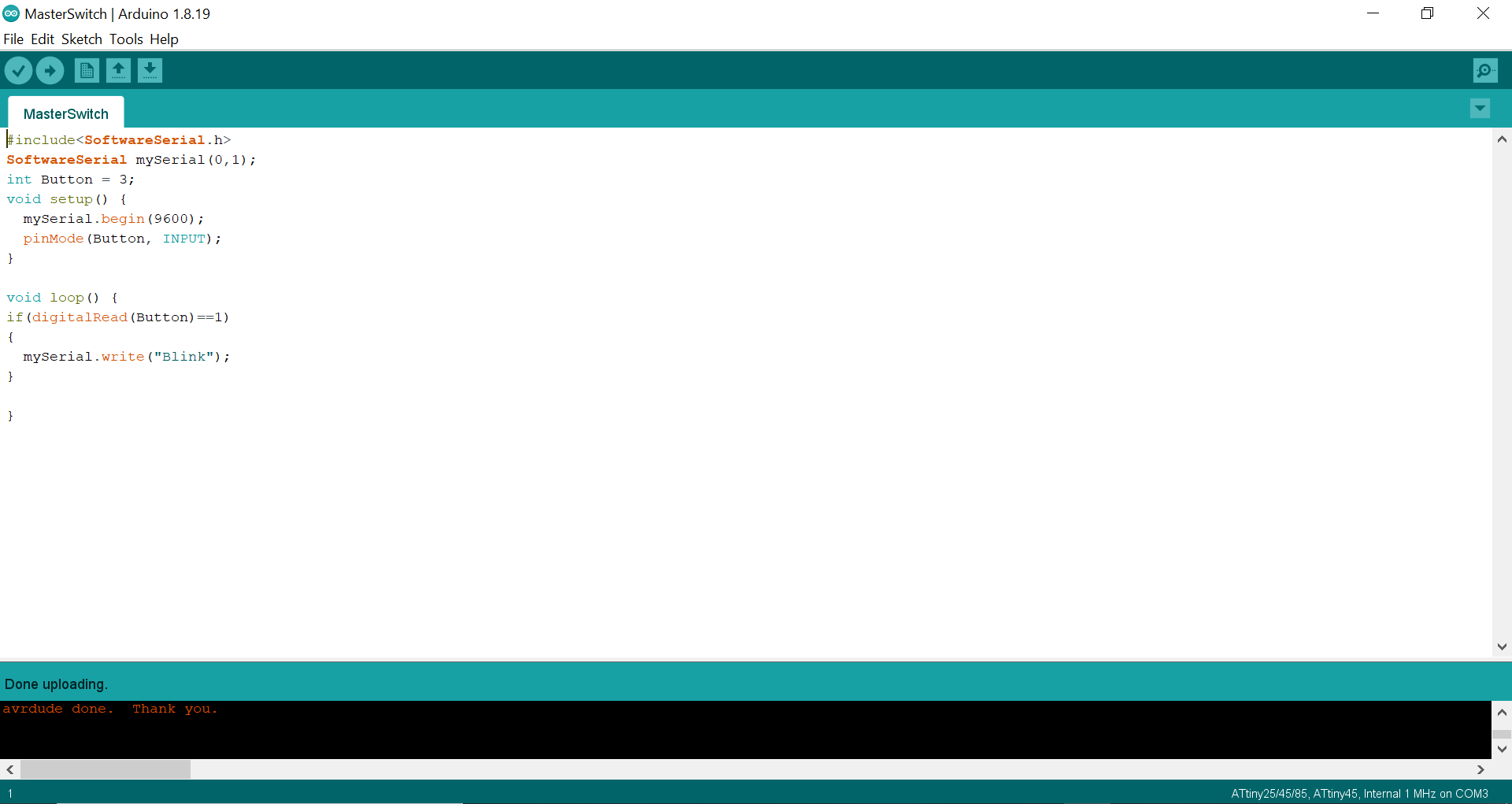
Programming
Master code
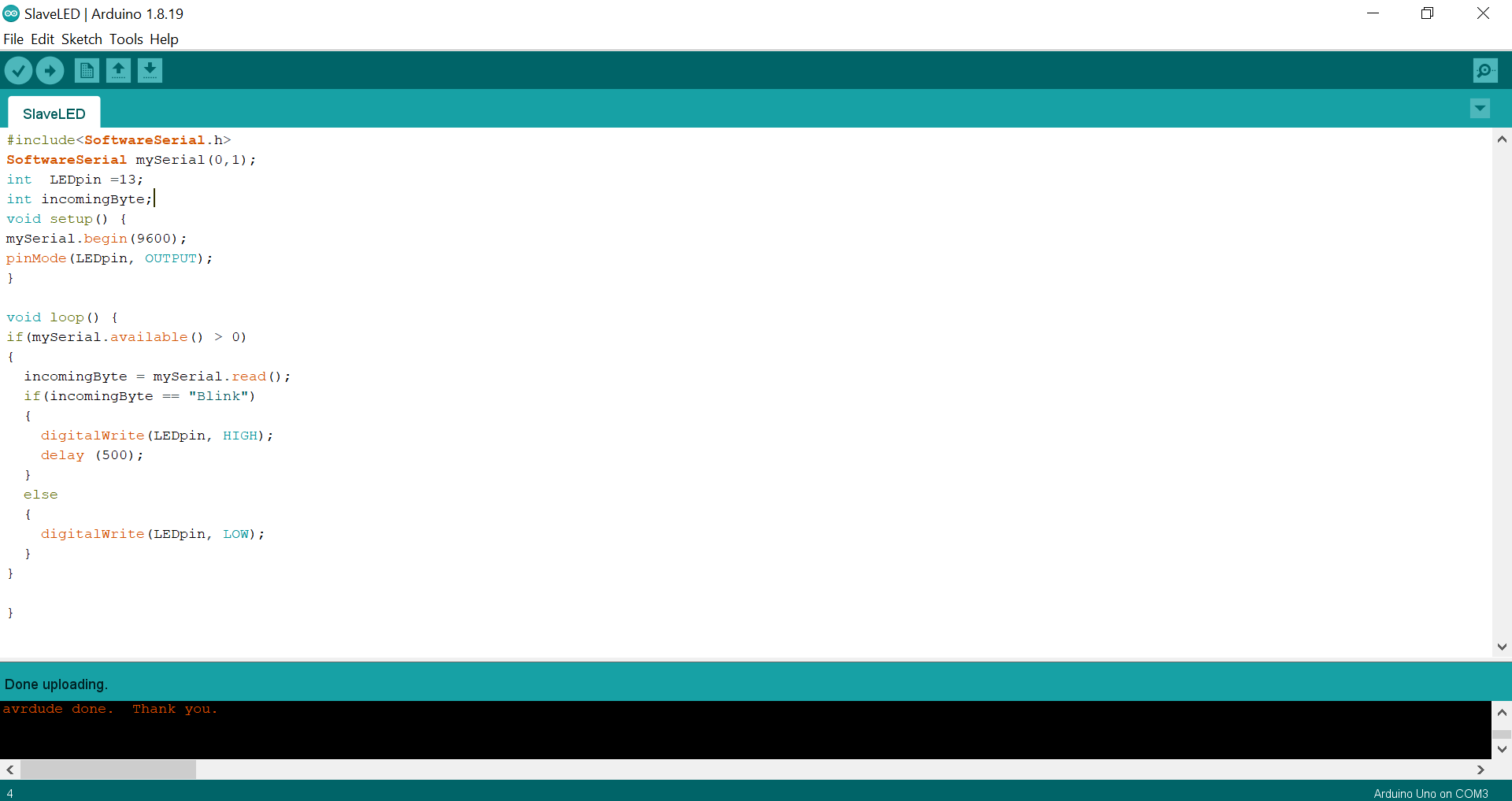
Slave code
After programing, my networking and communication between master and slave worked perfectly as you can see in this short video.