7. Electronics design
This week there are both individual and group assignments.
Assignments
- Use the test equipment in your lab to observe the operation of a microcontroller circuit board.
Individual assignment
- Redraw an Echo hello world board, add a button and LED, check the design rules, make it and check that it can communicate.
Group assignment
The group assignment was to use the test equipments in our local fablab to observe the operation of a microcontroller circuit board.
Reasearch
To carry out this assignment we have first identify the test equipments found in our lab and below are found test equiments:
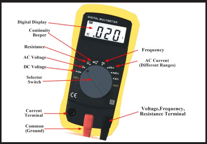
1. Multimeter
Multimeter is a measuring instrument that can measure multiple electrical properties such as voltage, current, resistance, and is also known as VOM as the unit equipped with Voltmeter, Ammeter, and Ohmmeter functionality; A device to measure electrical quantities and can be used also to measure electrical functions such as Voltage, Current, resistance, and can be able to measure electrical frequency. Below is the image of a Multimeter.
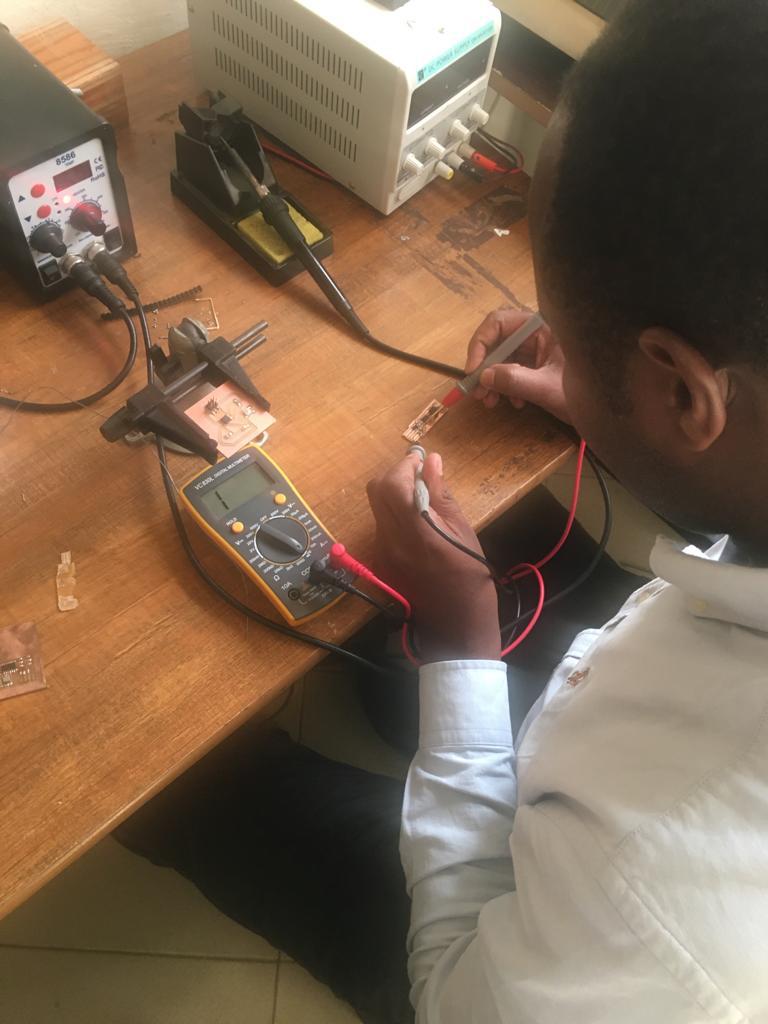
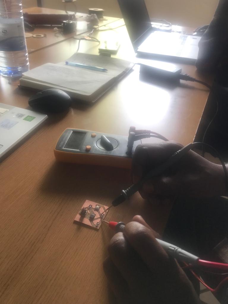
Below, is me using multimeter to check current continuity on my board.
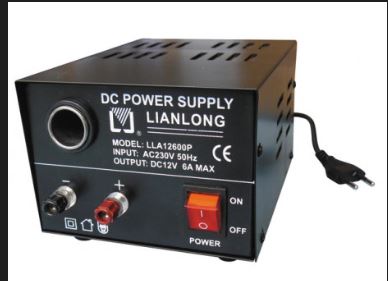
2. Power Supply
Power supply is an electrical device that supplies electric power to an electrical load; Its purpose is to convert electric current from a source to the correct voltage, current, and frequence to power the load. It is also reffered as electric power converter.
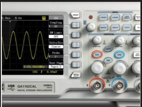
3. Digital Oscilloscope
Digital Oscilloscope is a complex electonic device constisting of various software and electronic hardware modules that work together to capture,process, view, and store data represanting the relevant signals of an operator; It is reffered as Digital Storage Oscilloscopes(DSO)or Digital Sampling Oscilloscopes(DSO).
6 Digital Oscilloscope elements:
a. Analog Vertical Input Amplifiers, b. Analog-Digital Converter And A Digital Waveform Memory c. A Time Base with a Trigger And Clock Drive d. Circuits for Waveform Displaying and Restructuring e. LED or LCD screen f. Power source
Digital Oscilloscopes work on the principle of sampling the signal from input thanks to high-speed microprocessors and you can be able to stop it at any time, trigger it at the desired level, recorded, and created again.
Digital oscilloscopes periodically sample a time-varying analog signal and store the signal values in relation to time in the waveform memory. Using built in clock, digital oscilloscopes compress input signals into separate time points; Instantaneously amplitude values are measured by an oscilloscope at taht point, the resulting digital displays are then Stored in a digital memory.
Digital Oscilloscope has the ability to store digital data for instance viewing, uploading to acomputer, creating hard copies or storing it on floppy disk,and measuring instantly on digital data over analog oscilloscope. After triggering event, digital oscilloscopes can display waveforms, while an analog oscilloscope needs to trigger before starting watching.
Individual assignment
Install Kicad and Libraries
To make a PCB design, I started by installing Kicad software got from this link and then I downloaded the fab electronics component library for Kicad.
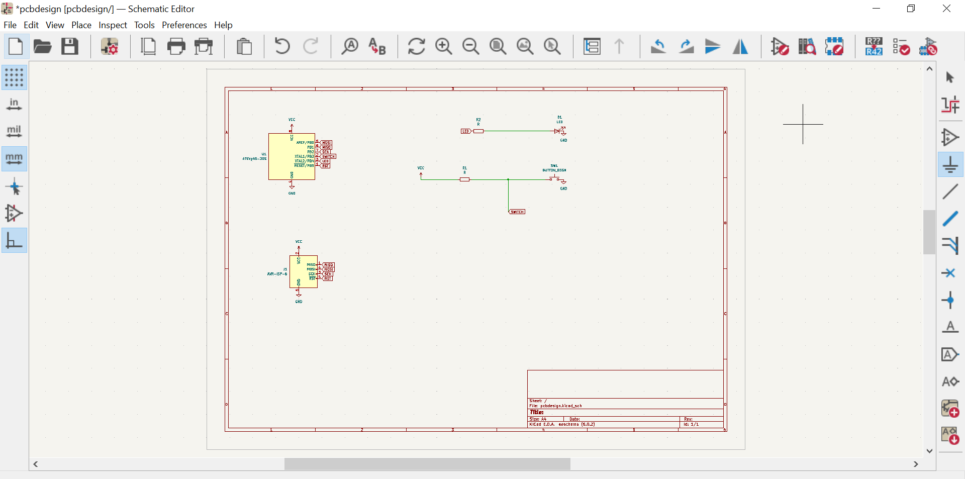
After installing all the libraries, all the components needed to make the PCb were put in the Kicad’s interface as you can see in the screenshot.
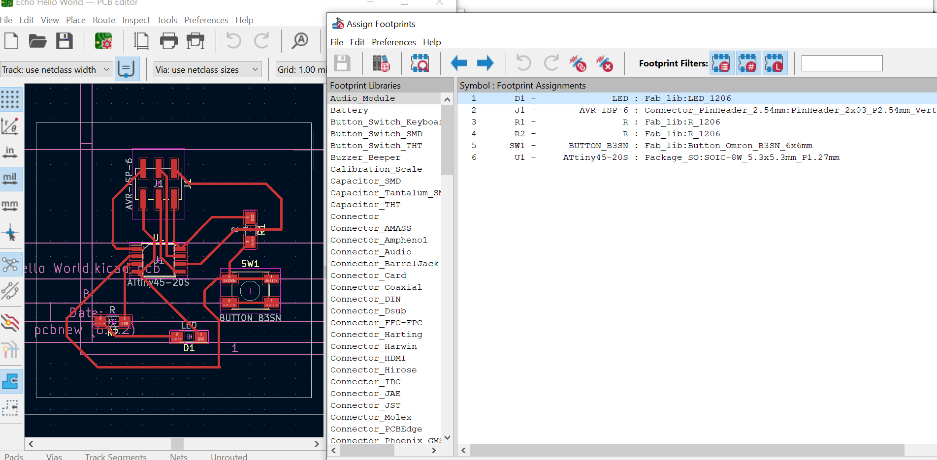
Secondly, I assigned the electrononic components to their footprints
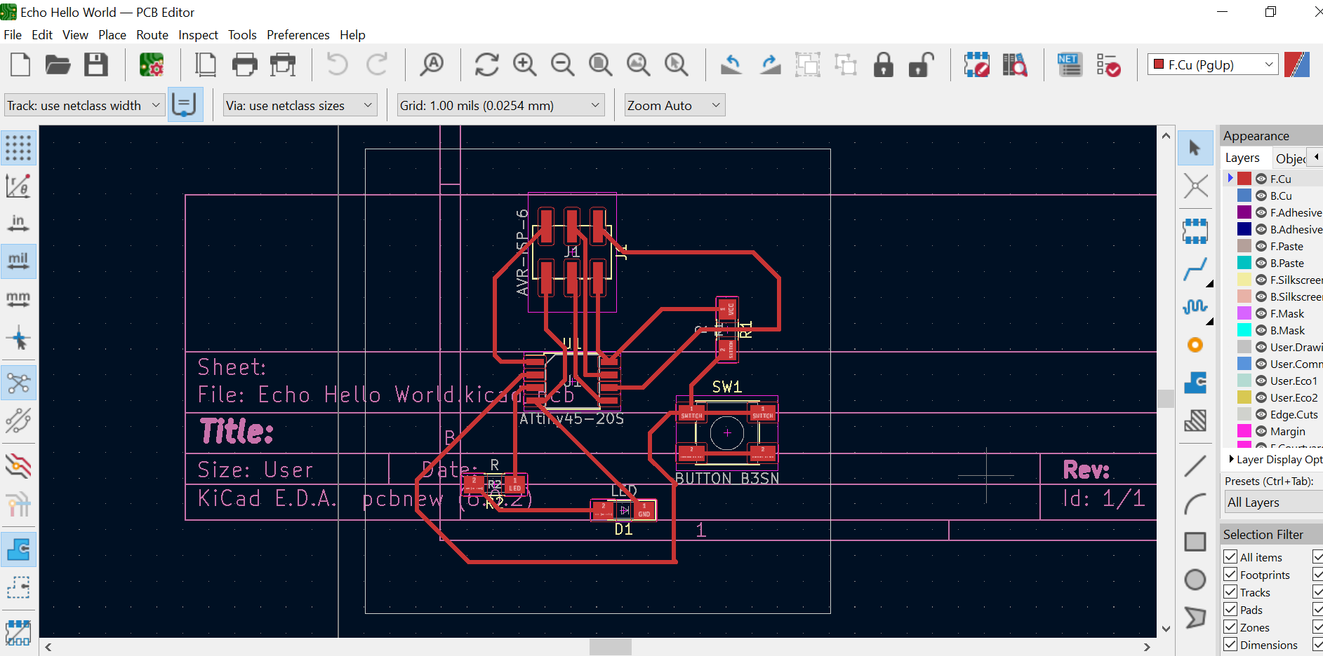
 Here is the final pcb design
 This is a 3D view of the PCB design

When the design in Kicad is done, I exported it in GIMP to get the png files.
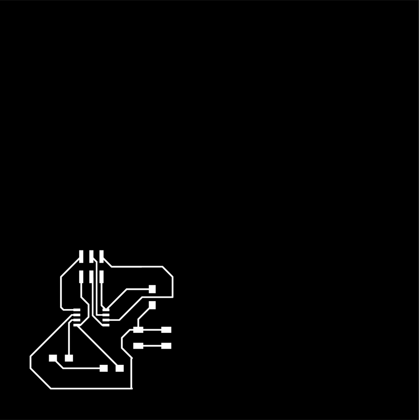

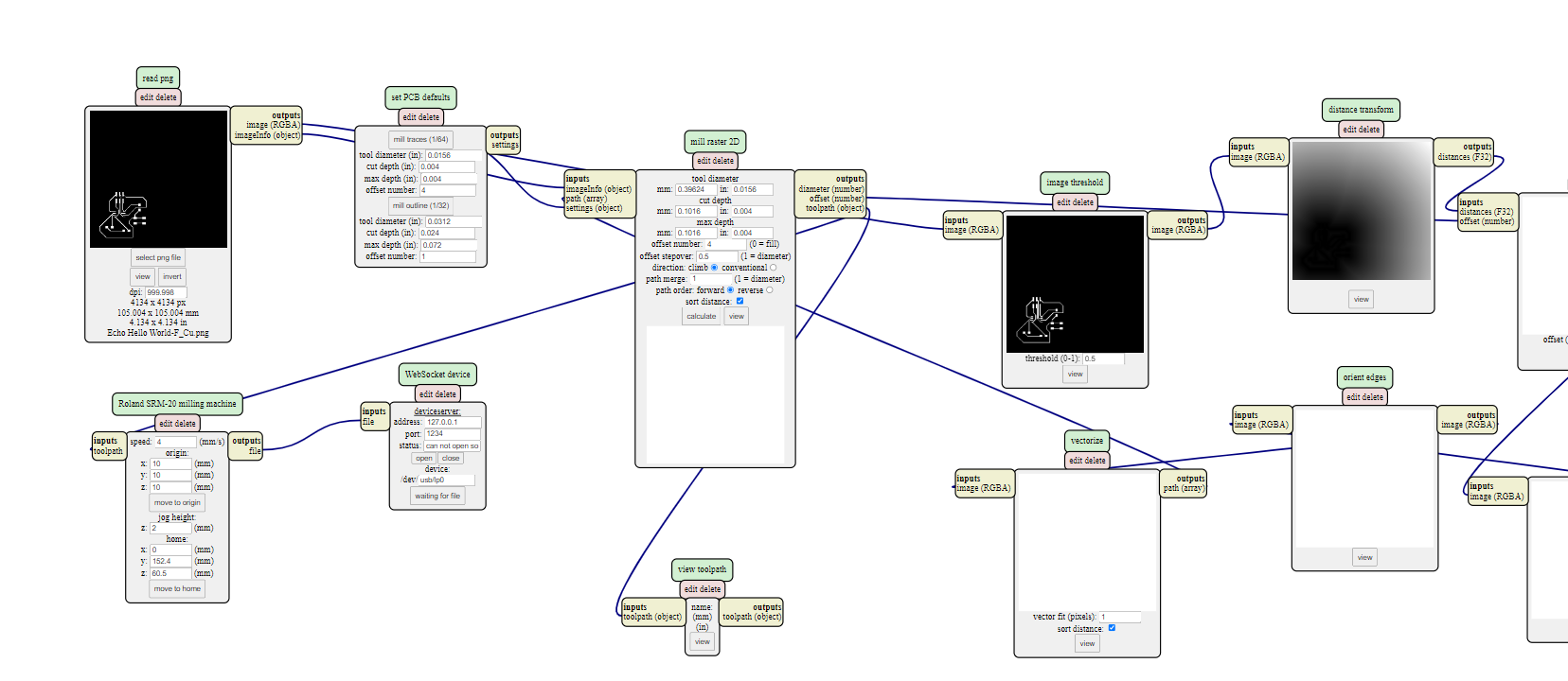
To get rml files, I exported png files in mods.
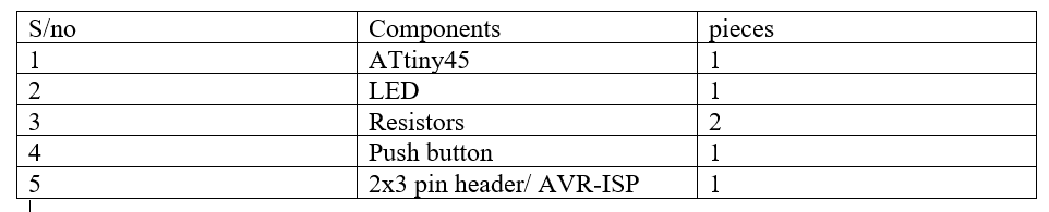
List of electronic components used
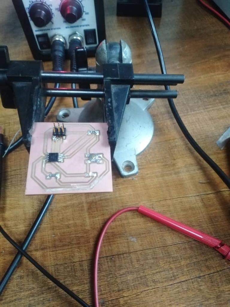
Final look of my pcb after soldering
After soldering my echo hello world I tested the continuity using the multimeter.
See original files here