11. Output devices
Assignments
Group Assignment: Measure the power consumption of an output device
Individual Assignment: Add an output device to a microcontroller board you’ve designed, and program it to do something
Group Page
Group Assignment
While I was working on the weekly assignment, our lab did not have a power supply or a device that could check the power consumption of the output device. Therefore, I checked what my instructor had done during her Fab Academy and learned by looking at other students’ measuring the power consumption.
Here is the link to my instructor’s page that shows power consumption: - Link
Individual Assignment
For the individual assignment, I worked with various output devices that I mentioned in week 11 of input devices. I worked with input and output devices simultaneously, as I needed to observe an output while working with inputs to ensure that I was doing the correct thing.
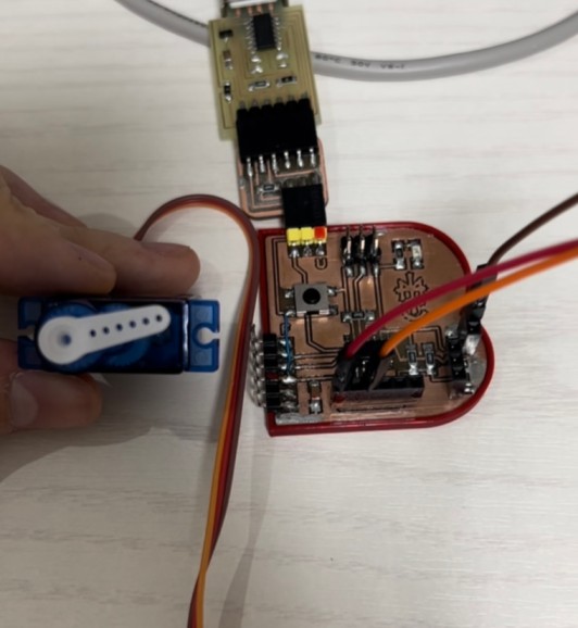
As discussed, some output devices that I used were servo motors and LED light. Another output device that I used here was neopixels, which I could run by using Adafruit in Arduino IDE. For the servo motor, the input used was turning the potentiometer while the output was the movement of the servo motor. For the programming process, I used an example code from Arduino for servo motors and changed the pins accordingly for the potentiometer. I also attached rainbow wires to a bread board, which allows us to make electric connections quickly.
For the servo motor, which has 3 terminals (power, signal, and ground), a potentiometer is used to move the servo motor 0° to 180°. 2 outer pins of the potentiometer are connected to VCC (power) and GND (ground). More information about the potentiometer (input) is in week 13. To connect the servo motor, I used a breadboard in which the potentiometer was also attached to. By placing the servo motor wires aligned with the wires for the potentiometer, I was able to start programming.
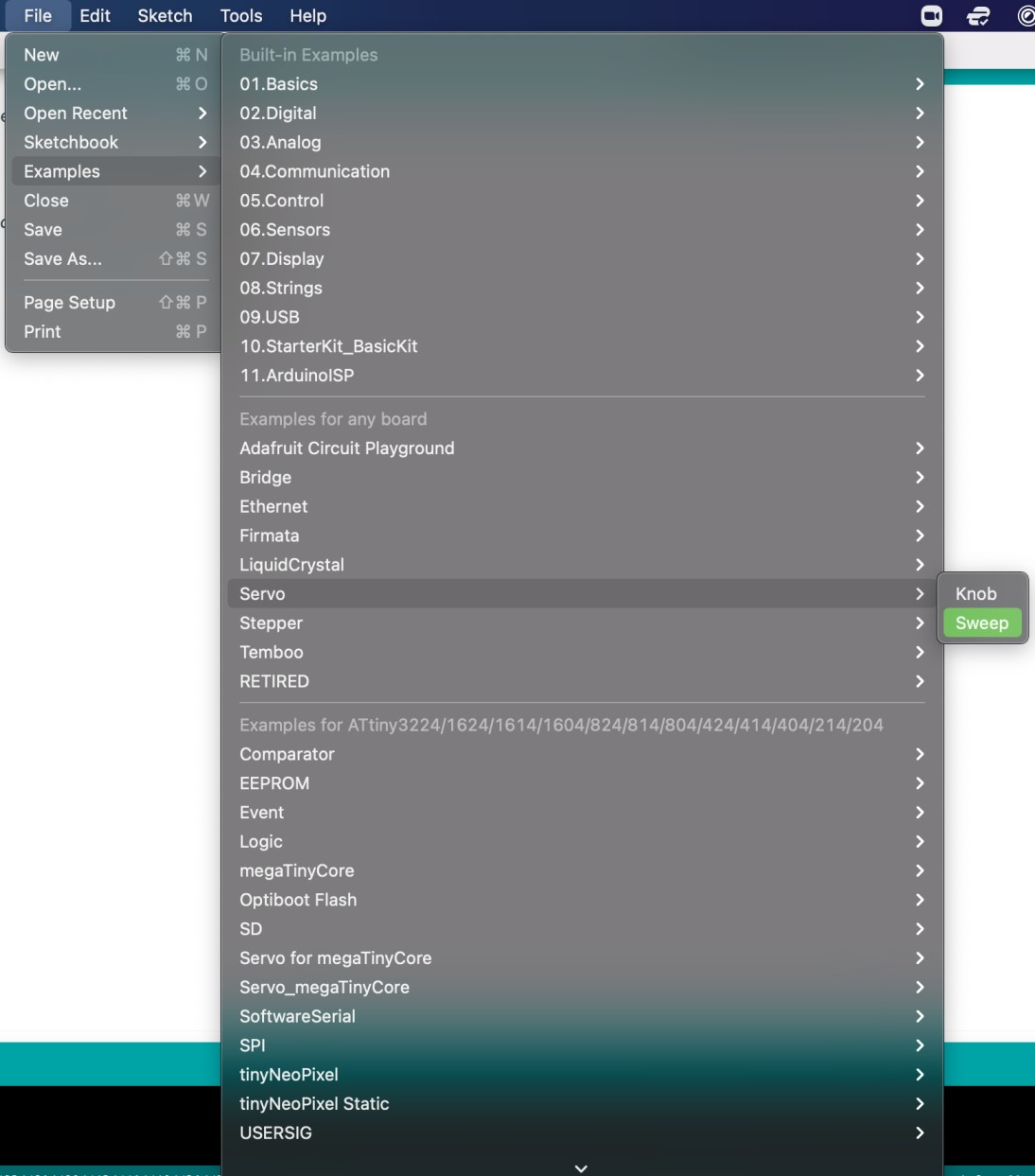
For the servo motor, the programming process was similar to what I had done to program the LED in week 9, which is linked below in the section about LED outputs. Again, I used an example code from Arduino for servo motors, which can be found following the steps in the image below.
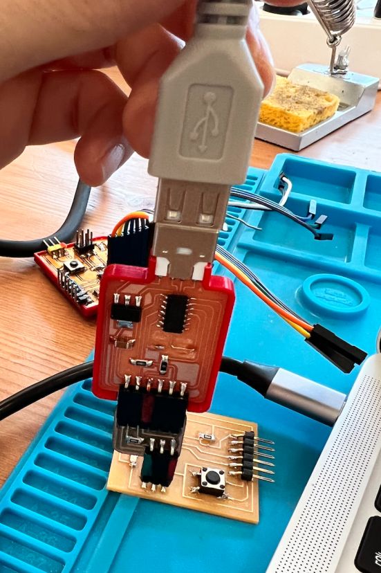
 Then, like week 9, I checked the board and chip that was properly connected and then burned the bootloader. Finally, I uploaded the code.
#include <Servo.h>

Servo myservo;  // create servo object to control a servo
// twelve servo objects can be created on most boards

int pos = 0;    // variable to store the servo position

void setup() {
  myservo.attach(9);  // attaches the servo on pin 9 to the servo object
}

void loop() {
  for (pos = 0; pos <= 180; pos += 1) { // goes from 0 degrees to 180 degrees
    // in steps of 1 degree
    myservo.write(pos);              // tell servo to go to position in variable 'pos'
    delay(15);                       // waits 15ms for the servo to reach the position
  }
  for (pos = 180; pos >= 0; pos -= 1) { // goes from 180 degrees to 0 degrees
    myservo.write(pos);              // tell servo to go to position in variable 'pos'
    delay(15);                       // waits 15ms for the servo to reach the position
  }
}
As I turned the potentiometer, I could observe the servo motors moving accordingly.
For the LED, I used the same code and process as what I described in week 9. Here is the link! The PCB I designed for electronics design already had the LED and button component, so I did not have to add an output component for this. - Link
When the button is pressed, the originally inactivated current flow is activated, and the circuit is completed for the current flow, which makes the LED glow. When the button is released (not pressed), the flow of the current will be blocked again, which is why the LED turns off. More information about the 4 pin button is in week 13 for inputs.
const int buttonPin = 10;     // the number of the pushbutton pin
const int ledPin =  6;      // the number of the LED pin

// variables will change:
int buttonState = 0;         // variable for reading the pushbutton status

void setup() {
  // initialize the LED pin as an output:
  pinMode(ledPin, OUTPUT);
  // initialize the pushbutton pin as an input:
  pinMode(buttonPin, INPUT);
}

void loop() {
  // read the state of the pushbutton value:
  buttonState = digitalRead(buttonPin);

  // check if the pushbutton is pressed. If it is, the buttonState is HIGH:
  if (buttonState == HIGH) {
    // turn LED on:
    digitalWrite(ledPin, HIGH);
  } else {
    // turn LED off:
    digitalWrite(ledPin, LOW);
  }
}
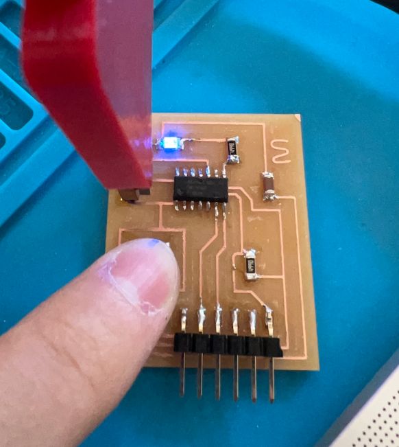
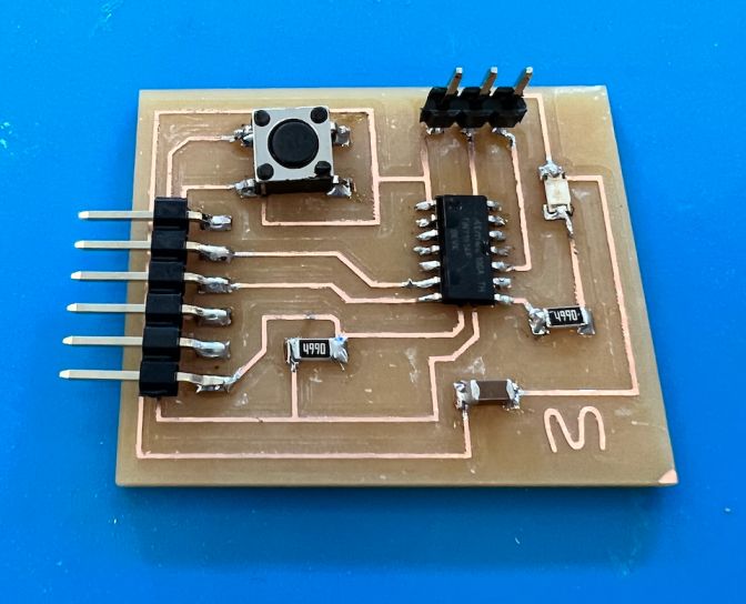
The board that I used for the LED output was the board that I designed during electronics design week.
Here is a hero shot of the board!
Troubleshooting
For this week, I did not encounter much problems because I had already included a button/LED component when designing my PCB. Also, I had already tried the LED programming before, and the servo motor programming was not much different. Most of the programming component came from example codes. From this week, the most difficult part was locating the pins in which the servo motor/potentiometer is, as I was not used to looking at pinouts. Moreover, I was confused when I connected the wires for the servo motor/potentiometer, as I was not used to reading the pinout and I often mixed up the pins for VCC and GND.