7. Electronics design
Group Assignment: Use the test equipment in your lab to observe the operation of a microcontroller circuit board
Individual Assignment: Redraw an echo hello-world board, add (at least) a button and LED (with current-limiting resistor), check the design rules, make it, and test that it can communicate Extra credit: simulate its operation
Test Equipment
For the first part of the week, I used a multimeter to observe the operation of the MCU circuit board. As mentioned in the previous week, a multimeter measures electrical quantities and checks for connections between traces.
To use a multimeter, place two probes in areas where you want to check the connection for. If there is a beep, this means that the two areas are connected.
Assignment
The assignment for this week was to redraw an echo hello-world board with at least one button and LED. To complete the assignment, I used Eagle, an electronic design automation application that allows PCB design using schematics and board design.
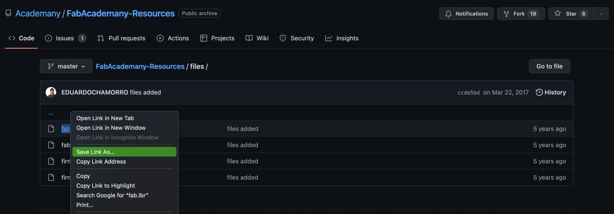
Before starting Eagle, I downloaded the Fab library by accessing the library uploaded in gitlab.
Here is the link I used in gitlab to download the library: - GitLab
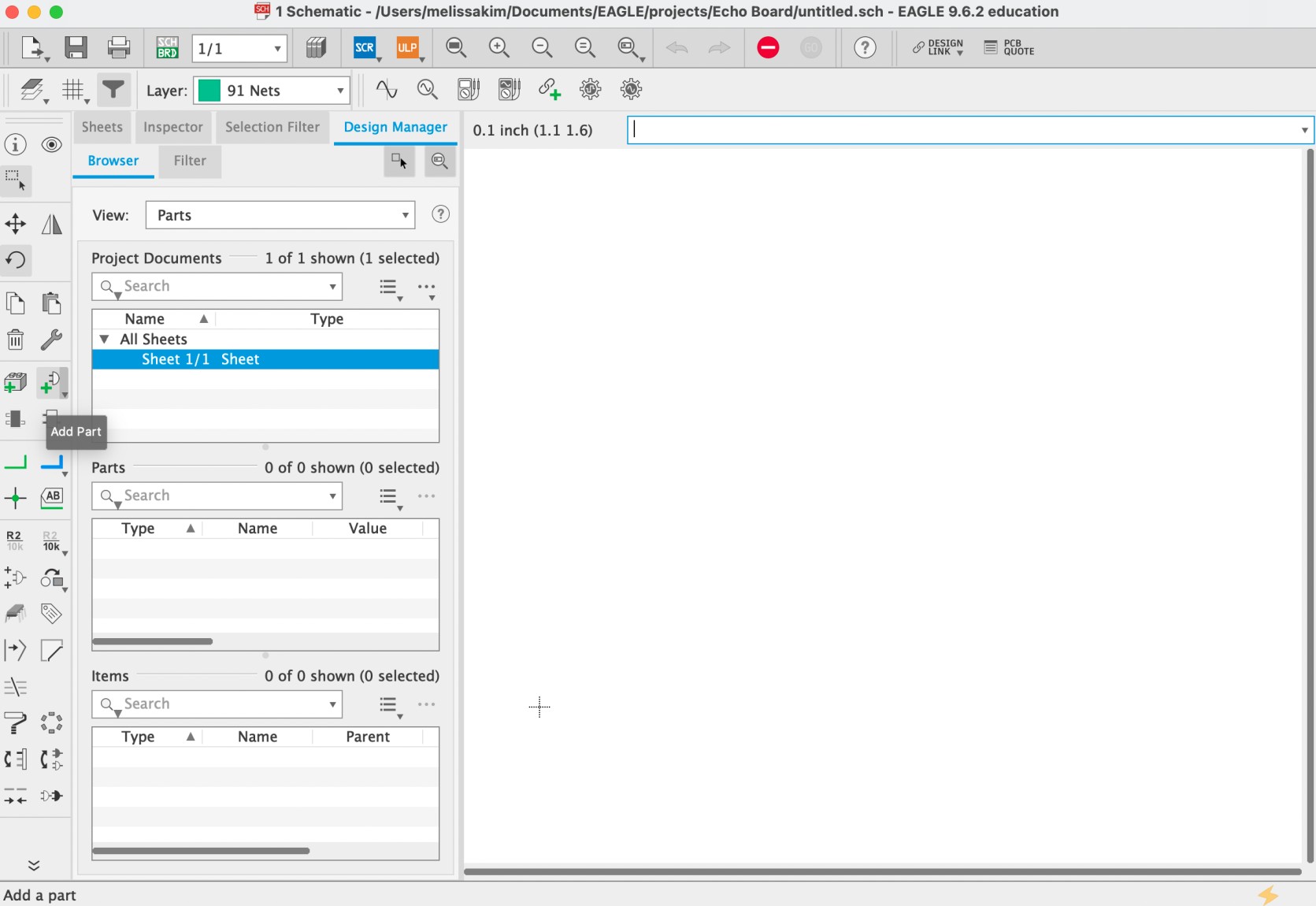
I then opened Eagle and opened a new project then opened a new schematics.
I explored various functions in schematics, such as labels, names, rotations, and movements. However, the most important component of the schematics section was the “add part” section in the left hand side menu, which allows us to access the library and the components inside the library requried for designing a PCB. For this “add part” function, you would select a component you are looking for, for example a resistor, and place it on your schematics. Then, you would press “esc” to exit from the library and work on the schematics page.
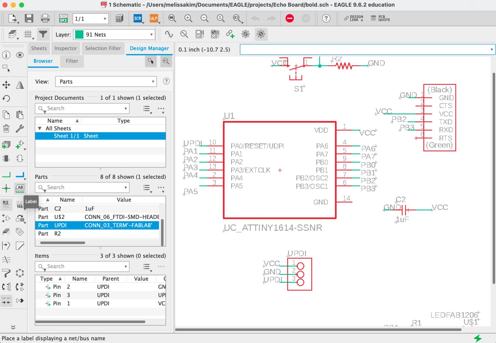
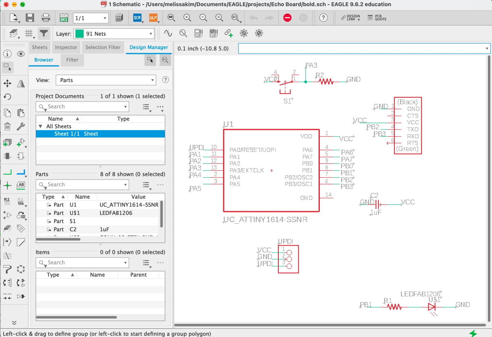
After adding all the required components including the button and the LED, I rotated and moved the components around accordingly. In the beginning, I connected parts that should be connected through lines; however, I realized that I could simply label them to connect and draw traces later on in the board section.
To make the circuits, I used “net” to create green lines protruding from the components and labeled them accordingly. For example, if I wanted to connect a component to GND, I would label the region of the component as “GND” and would confirm that I would want it to be connected with GND.
Also, I couldn’t find UPDI from this library. Therefore, I used a 3 pin connector and labeled them as UPDI, VCC, and GND.
After making the connections on schematics and confirming with my instructor, Miriam, I moved on to the board section.
In the board, I moved all components into the black box region and started making traces. For the board, the only difficulty I had was maneuvering the traces so that the traces do not overlap but result in connections for all necessary parts.
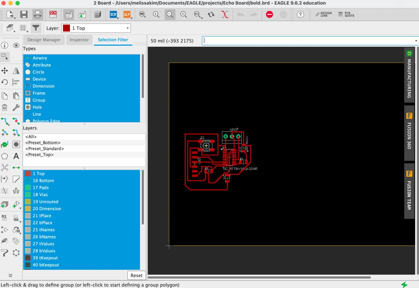 However, while making traces, I realized that I forgot to consider the ERC and DRC, which are electric and design rules that must be followed.
![]() I changed the ERC and DRC accordingly (I got help from Adrian Torres’ website regarding ERC) and made changes to the traces if necessary. Sometimes, the traces were overlapping since the change in ERC resulted in thicker traces. After this, I finalized my board.
I changed the ERC and DRC accordingly (I got help from Adrian Torres’ website regarding ERC) and made changes to the traces if necessary. Sometimes, the traces were overlapping since the change in ERC resulted in thicker traces. After this, I finalized my board.
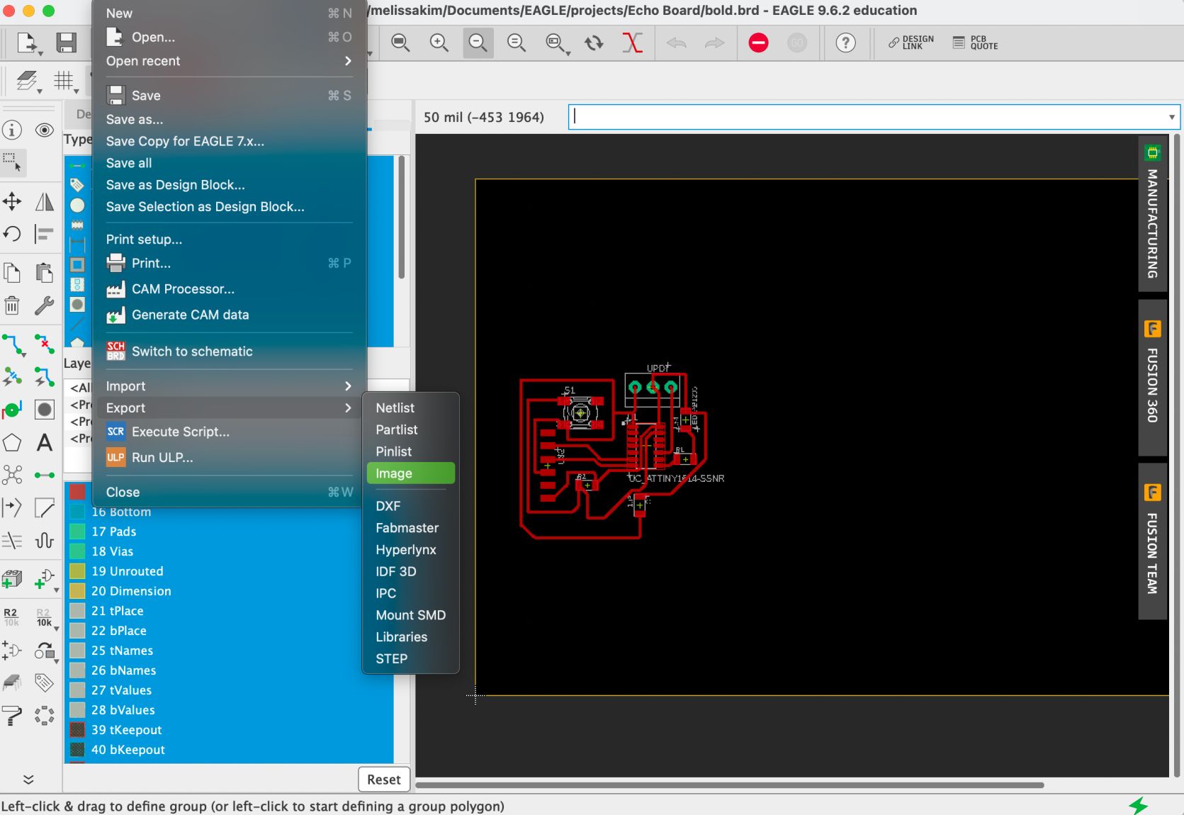 After exporting as an image file, I used illustrator to create the cuts and traces image that I would use in Mods CE.
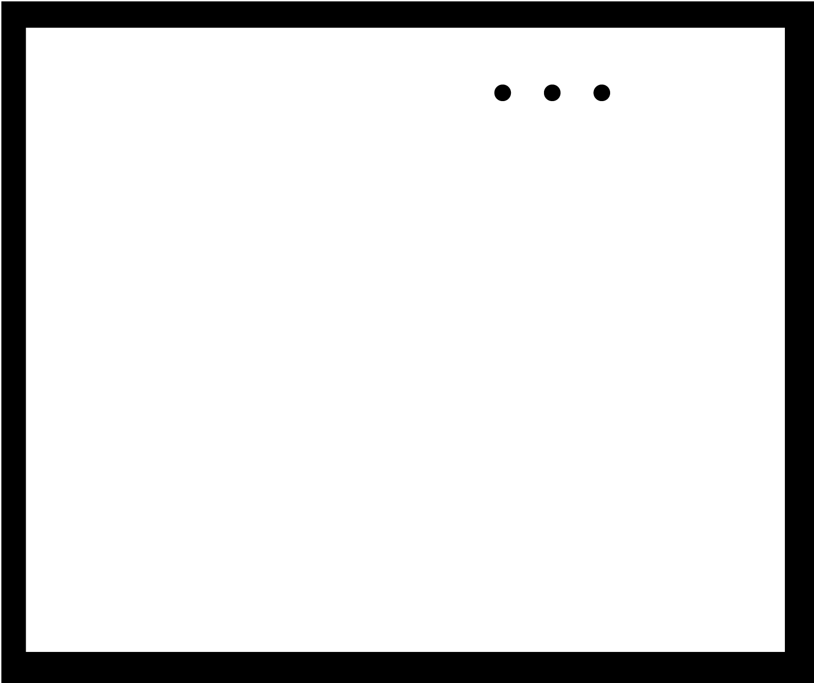
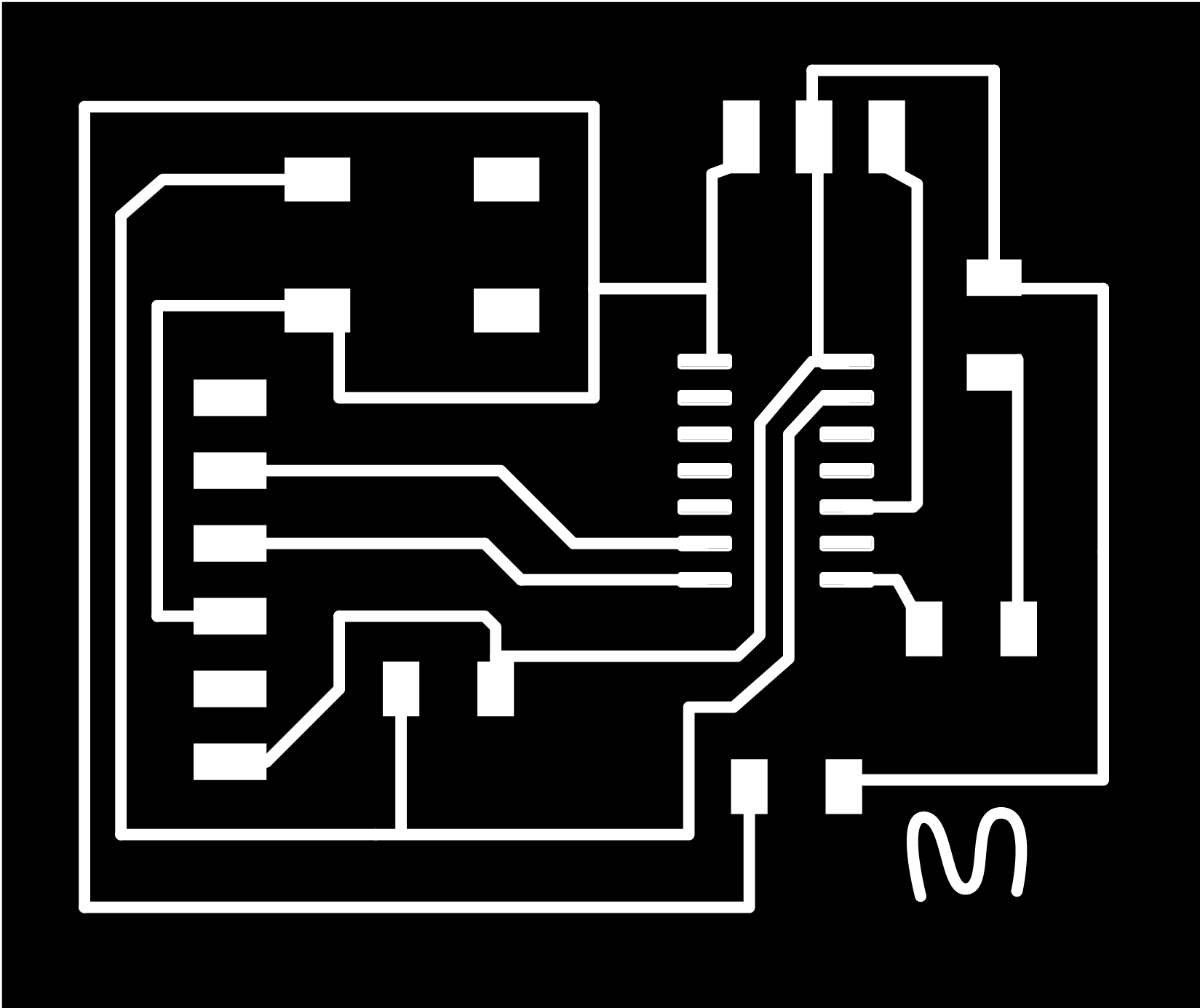 I uploaded the images for both the cuts and traces and downloaded G-codes that I would use to send to the CNC.
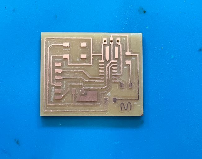
After CNC of PCBs
After completing the CNC process and milling my PCB, I had to remove burrs by using a sharp edge. The burrs may have been a result of a less-sharp tip of the endmill or a fast speed of the endmill which resulted in less accurate and deep cuts while milling.
 I then soldered necessary components onto the cleared board and tested the connections once again using a multimeter.
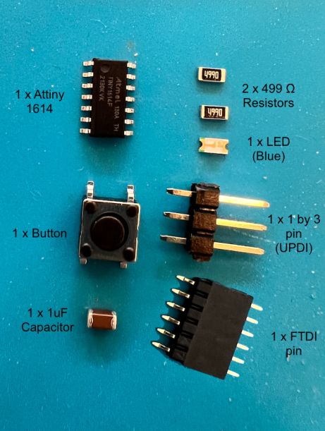
Here is the bill of materials!
1 * Attiny 1614
1 x 1uF capacitor
1x button
1 x FTDI pin
1 x LED (blue)
2 x Resistors 499 ohm
1 x 1 by 3 pin (UPDI)
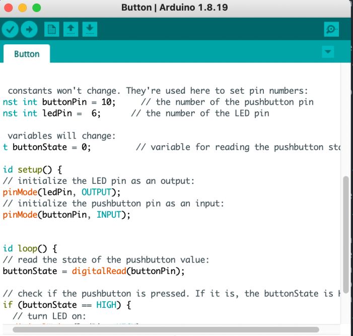
Programming
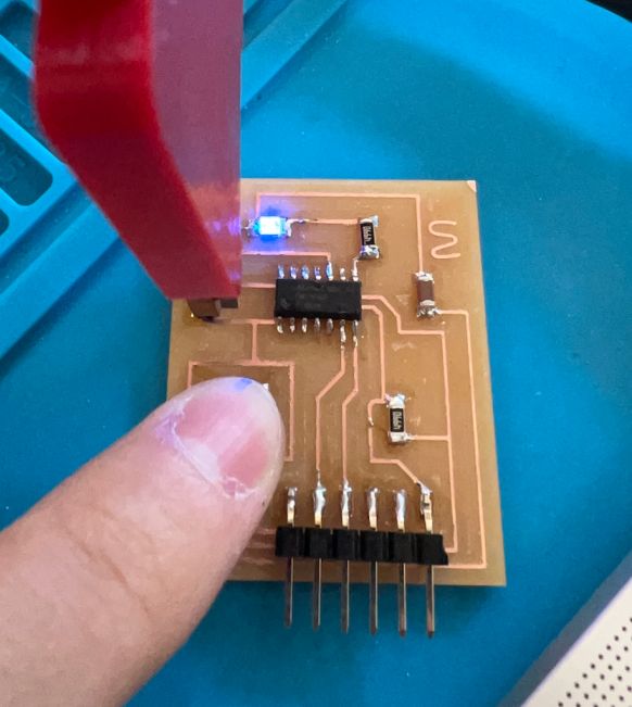
Again, for the programming portion, I checked the areas in which the LED and button connect and used Arduino IDE example codes to change locations and uploaded the code to the board. The result was turning on the blue LED like the image below.
Research
(Personal research and notes)
2 types of connectors to use with board ftdi and updi ftdi - serial reading/coding (receive and transmits with serial rx and tx pins) updi - only 2 pins (updi pin)
micrprocessors samd 11 board pictures
week 5 group project 1/64 (0.4mm) 1/32 (0.8mm) carbide steel endmills
burring - may have been due to not sharp endmill or fast speed