13. Input devices
Group assignment: probe an input device’s analog levels and digital signals
Individual assignment: measure something: add a sensor to a microcontroller board that you have designed and read it
Sensor
For this weeks assignment, I learned about different inputs that I could use. I experimented with potentiometers and buttons.
For the button, I used a 4 pin button which was connected using rainbow connectors/wires. When the button is not pressed and is therefore not activated, pins 1 and 2 are connected and pins 3 and 4 are connected. However, when the button is pushed and activated, pins 1 and 3 are connected together, while pins 2 and 4 are connected together, as shown below in the image.
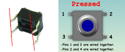
When the input button was pressed, it resulted in an output of a LED light turning on/off.
The code that I used for the button is as follows:
const int buttonPin = 10;     // the number of the pushbutton pin
const int ledPin =  6;      // the number of the LED pin

// variables will change:
int buttonState = 0;         // variable for reading the pushbutton status

void setup() {
  // initialize the LED pin as an output:
  pinMode(ledPin, OUTPUT);
  // initialize the pushbutton pin as an input:
  pinMode(buttonPin, INPUT);
}

void loop() {
  // read the state of the pushbutton value:
  buttonState = digitalRead(buttonPin);

  // check if the pushbutton is pressed. If it is, the buttonState is HIGH:
  if (buttonState == HIGH) {
    // turn LED on:
    digitalWrite(ledPin, HIGH);
  } else {
    // turn LED off:
    digitalWrite(ledPin, LOW);
  }
}
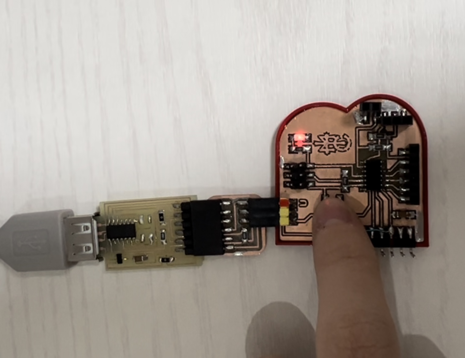
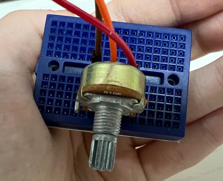
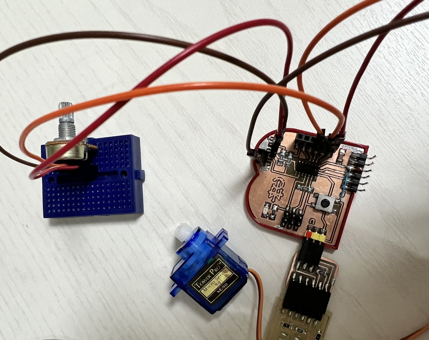
Another input device that I used was a potentiometer, which works by altering and varying the position of the sliding contact across a uniform resistance. The degree of the resistance is determined by the turning of the wiper, or the potentiometer knob. The potentiometer regulate the voltage and current using 3 connection points. For the potentiometer, I connected it to the board using a bread board and rainbow wires/connectors. Using the code in Arduino IDE, I was able to observe the change in data as I turned the potentiometer up and down (the numbers in the data changed drastically). Moreover, another output that I connected was a servo motor. As I manipulated the potentiometer, I could observe the changes being made as the servo motor moved accordingly.
Before connecting the potentiometer with the output (servo motor), I first tried the serial read using the potentiometer.
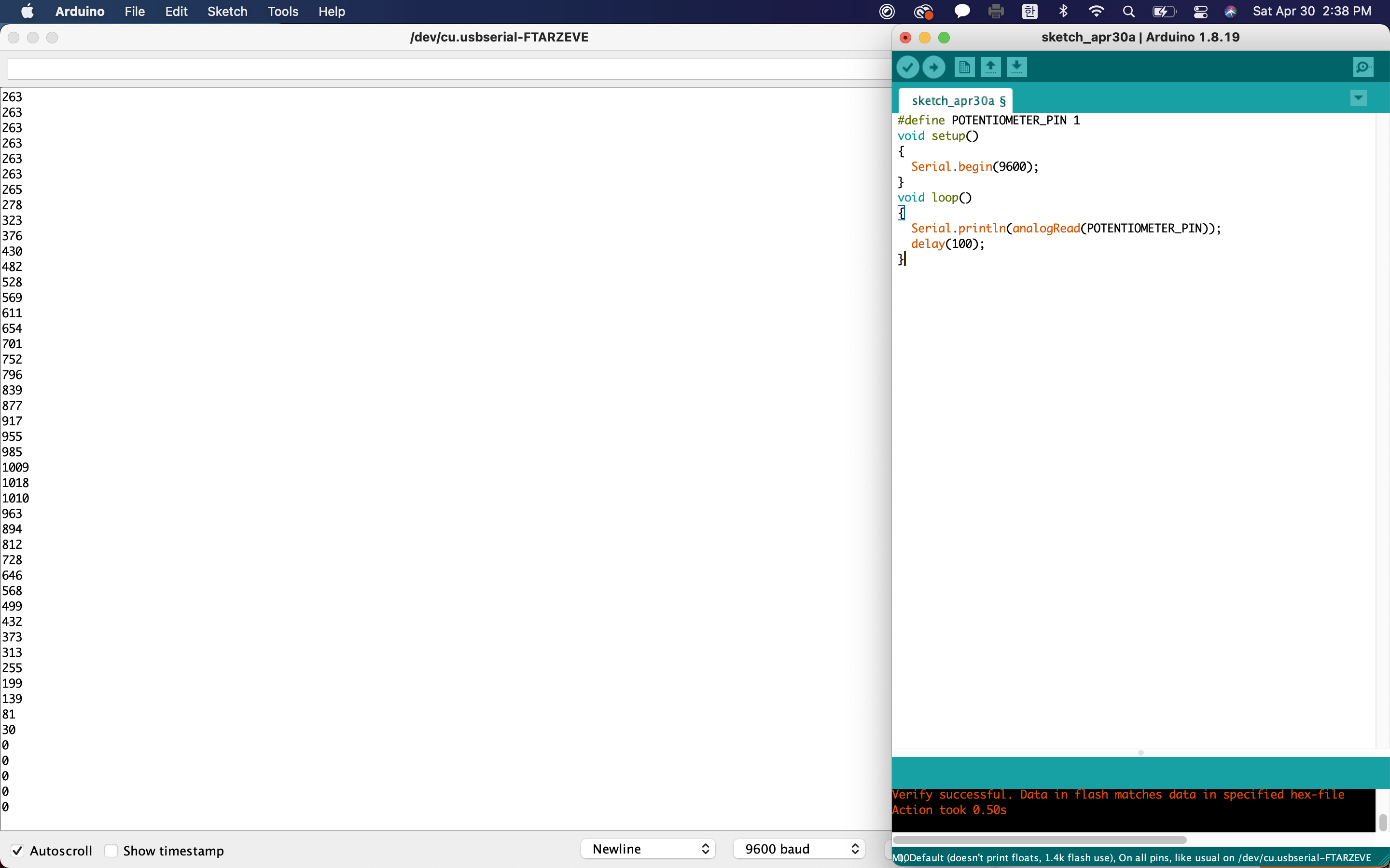 By turning the potentiometer, the amount of resistance is altered at the 2 pins on either side, which results in a change in ocltage of the pin at the center. The voltages at the center pin results in the serial read of the potentiometer. The tutorial that I used to learn and obtain the code is linked below:
- Link
By looking at the serial read, I was able to statistically see the voltage changing as I turned the shaft of the potentiometer, which allowed me to understand how the potentiometer resulted in the servo motor moving.
By turning the potentiometer, the amount of resistance is altered at the 2 pins on either side, which results in a change in ocltage of the pin at the center. The voltages at the center pin results in the serial read of the potentiometer. The tutorial that I used to learn and obtain the code is linked below:
- Link
By looking at the serial read, I was able to statistically see the voltage changing as I turned the shaft of the potentiometer, which allowed me to understand how the potentiometer resulted in the servo motor moving.
 The output of the potentiometer input was the movement of the servo motor.