5. Electronics production
This week I worked on electronics production!
Assignments
Group Assignment: Characterize the design rules for your in-house PCB production process (Extra Credit: Send a PCB out to a board house)
Individual Assignment: Make an in-circuit programmer that includes a microcontroller (Extra Credit: Customize the design / Mill and stuff the PCB / Test it to verify that it works)
Extra Credit: Try other PCB processes!
Group Page
Here is the link to the group page: - Group Page
PCB Research
For this week, I designed my own PCB, or printed circuit board. I had some previous experience regarding PCBs, as I had used PCBs for another personal project to make hearing-aids. However, this was the first time I designed my own PCB, so I had to do prior research.
Before starting the designing process, I looked up key aspects of the PCB and its components. I learned about the resistor, capacitor, and other components. The resistor is an electrical component that “resists” or regulates the flow of electrical current, while a capacitor is a device used for storing electrical energy (two conductors). A resistor is measured in the unit “ohm” while a capacitor is measured in the unit “farad”.
Milling (CNC)
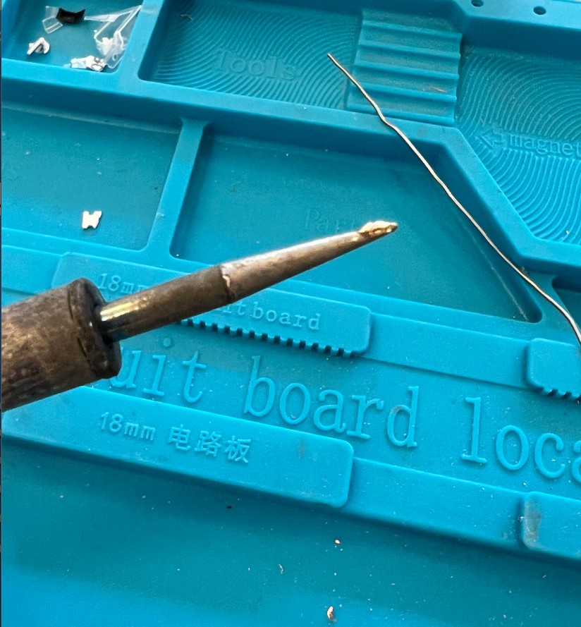
Also, this was my first time using the CNC machine, so I decided to test out the machine before milling a PCB. For this week, we worked with a 3018 PRO CNC machine and Vblades as well as a 0.8mm PCB milling tool.
The image below shows the tools that we used for the local session!
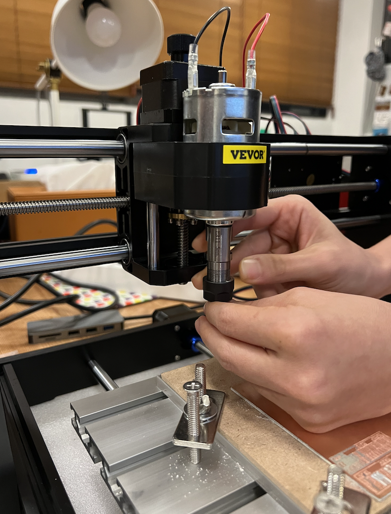
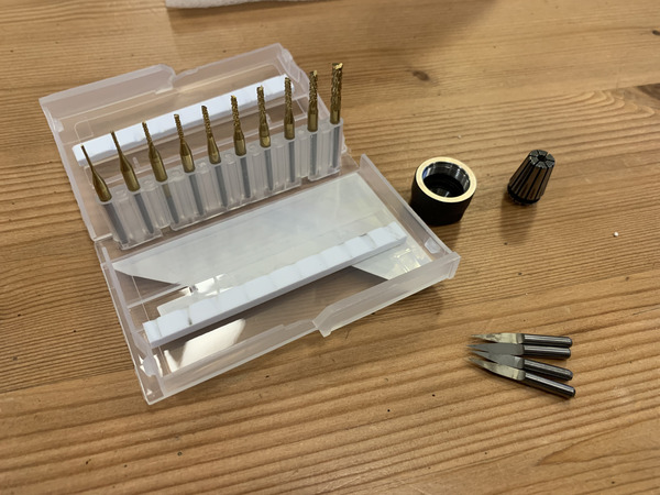 For the 3018 PRO CNC machine, we had to manually manipulate the collet for the Z axis. We used a wrench and then physically loosened up the collet using our hands to adjust the blade and the unit to be in contact with the PCB.
A 1/32 endmill was used with the 3018 PRO CNC machine.
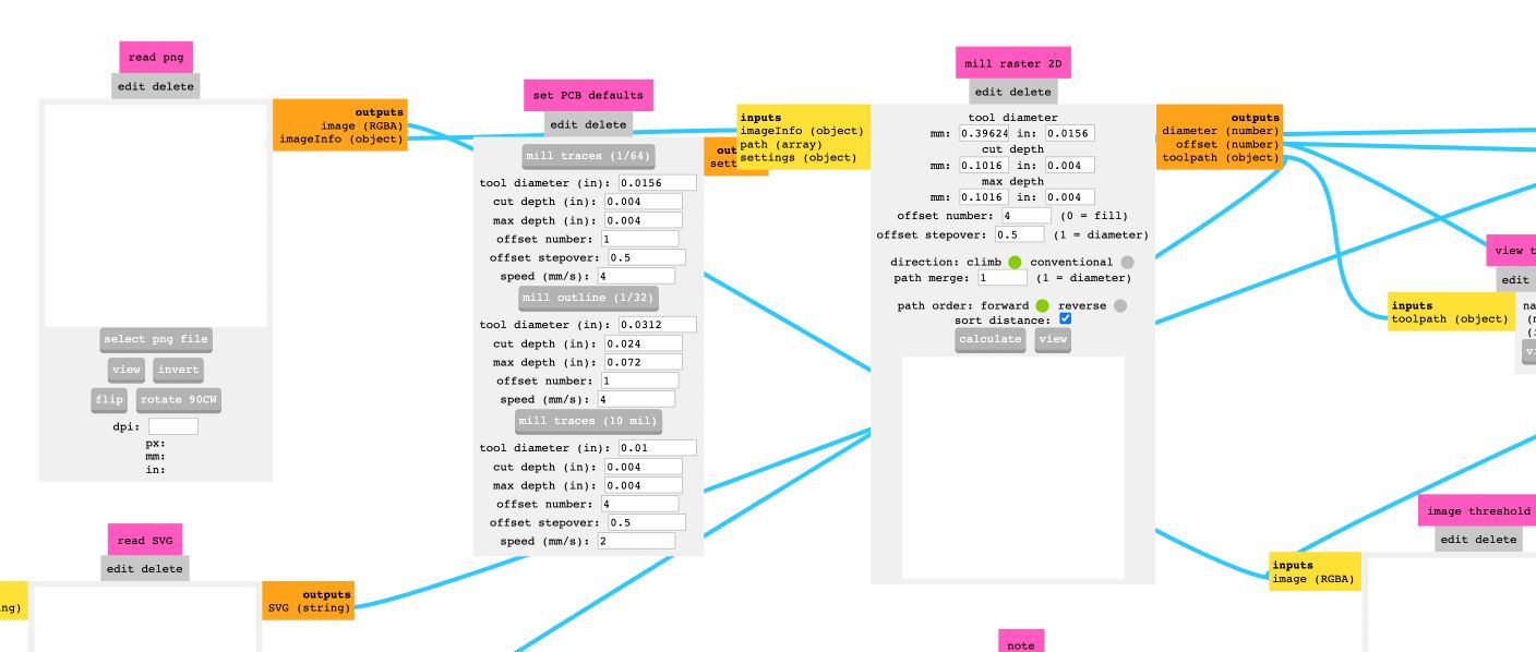
 Then we navigated to the FabAcademy website and accessed the Community Edition MODS. Using this, we then created the Gcode for the 3018 PRO CNC! We learned about the settings for the MODS and tested the settings out.
 To test, we produced a logo of our lab, BOLD Lab!
 The results were clear and proved that the settings were programmed correctly.
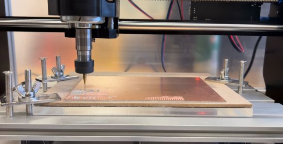
For this week, I cut a PCB that was designed by the BOLD lab and created a SAMD11C programmer, which contains low-power MCUs using the 32-bit pin.
Using my PCB design, I obtained the G-Code from MODS and sent it to the CNC machine. After the traces were cut, we manually removed the burring by using a sharp edge (knife) and cleaned up the board. Then, I used a multimeter to check the connections and to ensure that parts that were in close contact but aren’t supposed to be connected to each other weren’t connected.
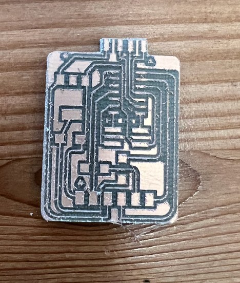 Here is a hero shot of the board:
The same process for this week was used after designing my own board in week 07, as I milled, soldered, and programmed that board using the same procedures as what is described in this week.
Soldering
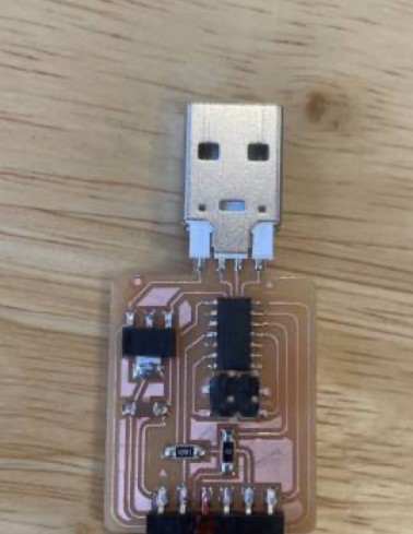
Once the PCB was cut for my design, I soldered and attached necessary components to the board. I had previous experience with soldering, so I did not practice much before soldering my board. Again, I checked the connections with a multimeter.
For smaller materials that were difficult to solder due to it moving on the board, I started by adding a small amount of soldering iron on the board, then placed the material and then re-melted the iron to stabilize the material on the board. Then, I used regular soldering processes such as placing the soldering gun on for 3 seconds and then shortly exposing the soldering ion to the gun to melt in place.
 As seen here, the bottom 2 pins on the right were soldered to stabilize the movement of the material on the board.
The materials used are shown below.

Programming
I then decided to program my board so that it could have a function. For the board, I used Arduino IDE and used rainbow cables to create connections. To program, I had to download a library in Arduino called Mattair Tech, which I downloaded by copy and pasting this URL (https://www.mattairtech.com/software/arduino/package_MattairTech_index.json) into the boards manager, which can be found under “preferences” in Arduino. The URL I copied was obtained from FabLab Kannai’s website! - FabLab Kannai
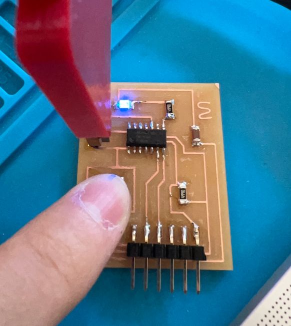
For my own board, the input was a button and the output was LED. I programmed the board to turn on the LED using Arduino’s example code for button and modified it (This is the same process used as the input/output week since buttons and LED were involved). The blue LED below confirms that the programming was successful and the PCB works!
The code that I used for the button is as follows:
const int buttonPin = 10;     // the number of the pushbutton pin
const int ledPin =  6;      // the number of the LED pin

// variables will change:
int buttonState = 0;         // variable for reading the pushbutton status

void setup() {
  // initialize the LED pin as an output:
  pinMode(ledPin, OUTPUT);
  // initialize the pushbutton pin as an input:
  pinMode(buttonPin, INPUT);
}

void loop() {
  // read the state of the pushbutton value:
  buttonState = digitalRead(buttonPin);

  // check if the pushbutton is pressed. If it is, the buttonState is HIGH:
  if (buttonState == HIGH) {
    // turn LED on:
    digitalWrite(ledPin, HIGH);
  } else {
    // turn LED off:
    digitalWrite(ledPin, LOW);
  }
}
 For the example BOLD PCB, LED was also used to test that the PCB was working. The same code was used, but the pin numbers for where the LED and button were located at was modified.
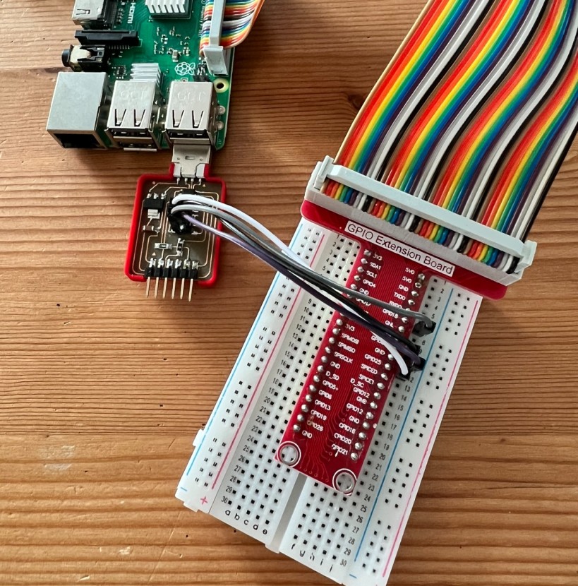
 I also got help by looking at FabLab Kannai’s website to program the SAMD11C board using Raspberry Pi:
- FabLab Kannai
I also got help by looking at FabLab Kannai’s website to program the SAMD11C board using Raspberry Pi:
- FabLab Kannai
Bolduino
To program the board, the Bolduino board (from BOLD lab) was used for UPDI connection. Here are the pin details for the Bolduino.


Functionality and problems
I confirmed that my PCB board was functional, as the multimeter check showed me that parts that were meant to be connected were connected and that other parts were not connected. Also, I verified that the PCB works by programming the board so that blue LED appears when a button is pressed; a blue LED did turn on, which proves that the board is functional.
Some problems I encountered while creating the board was regarding the CNC settings, as a greater degree of burring may have resulted in loose connections.