4. Computer controlled cutting
This week, I worked on computer controlled cutting. I really enjoyed designing and using the vinyl cutter.
Assignments
Group Assignment: Characterize your laser cutter’s focus, power, speed, rate, kerf, joint clearance and types
Individual Assignment: Cut something on the vinyl cutter / Design, lasercut, and document a parametric construction kit, accounting for the lasercutter kerf, which can be assembled in multiple ways
Extra Credit: Include elements that aren’t flat
Group Page
Before starting the website, here is the link to the group page for BOLD Lab Seoul! - Group Page
Laser Cut Parameters
A laser cutting works by using a power laser directed by CNC to emit a precise and accurate beam based on the file that is loaded to cut. On wood, the laser burns the wood results in a cut. Besides cutting, laser cutting can also be used for engraving. Moreover, other than wood, acrylic or other materials can be used with laser cutting as well.
Some important parameters to consider for laser cutting are power and speed. The settings for power and speed used for cherry wood are shown in the image below.
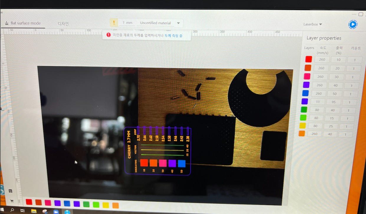 Power parameter: The power setting is responsible for the output of the laser cutting, and a high power is often used for dark wood engravings. The range of the power parameter is between 0 % to 100 %.
Speed parameter: The speed parameter is responsible for the movement of the laser itself, and the speed is inversely related to the exposure time. However, it is important to note that a very high speed can result in inaccuracies such as less-deep laser cuts (not cut properly). The range of the speed parameter is between 0 % to 100 %.
Kerf
Before starting the parametric designing process, I was introduced to the concept of kerf. Kerf is the width of the material that would be cut or burned away, and therefore must be considered for the design.
To check the kerf, I made a board for Bass Plywood 3mm containing standards for engraving, vector, and kerf, as I wanted to use bass plywood insted of cherry wood, which I used to describe the parameters.
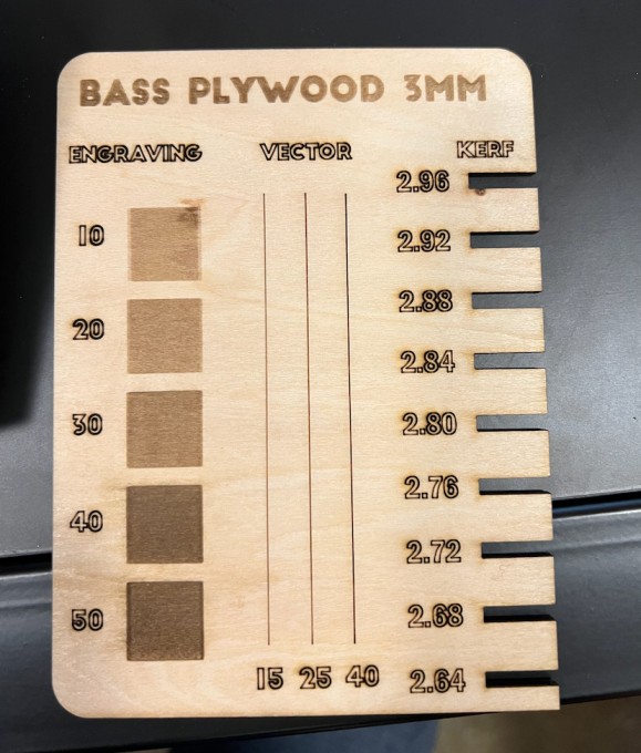
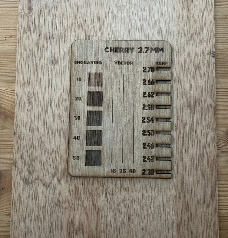 The Bass Plywood was labeled as 3 mm, but in reality, it was 2.7 mm when I used a caliper to measure.
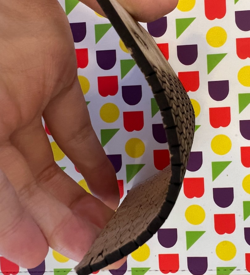
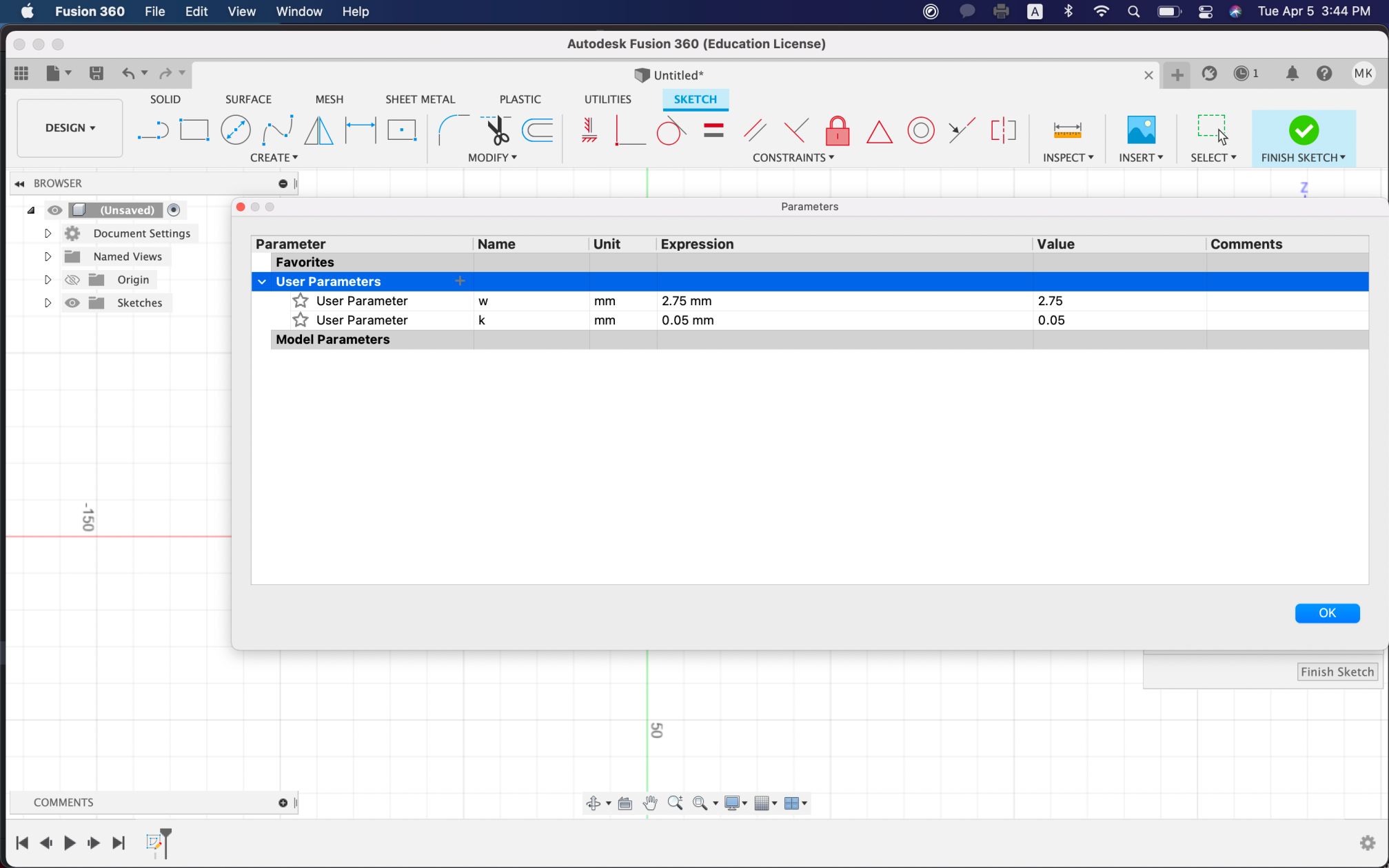
For the kerf, I had to find the difference betwen the kerf on board and the material; for mine, the difference was 0.1 mm. Since there are 2 sides to consider for the kerf (both left and right, or top and bottom, depending on the way you look at it), we divide the difference into 2, making the kerf 0.05 mm. I also experimented with kerf for bending and flexibility.

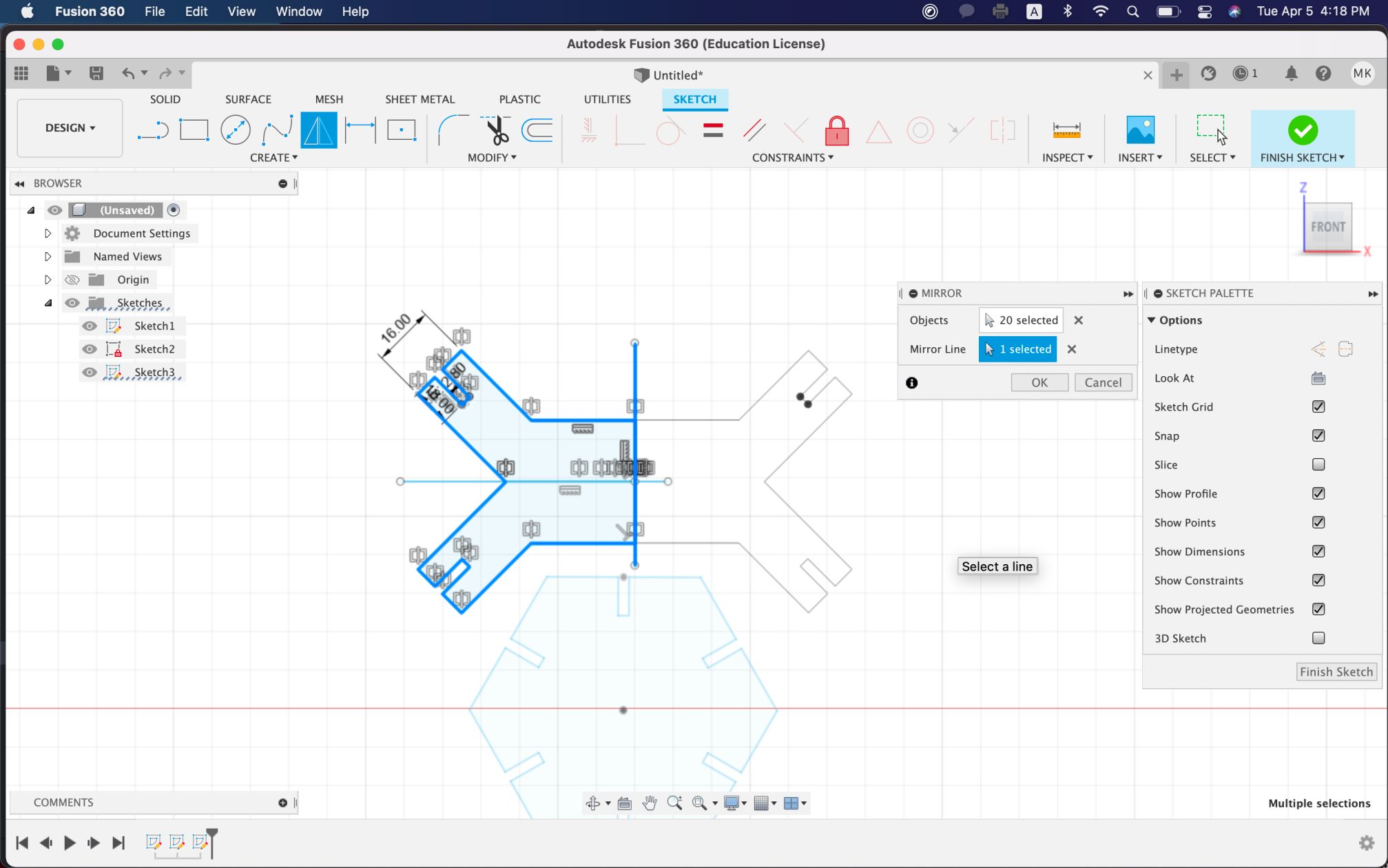
Parametric Designing
I was then introduced to parametric designing, which is the use of input parameters throughout the design without manual input. This allows for easy changes in parts of the design where the measurement changes, as certain parameters are already assigned; we do not have to manually change and find all errors if a measurement change is made. For example, parameters could be assigned for width (w) and kerf (k), so instead of numerically inputting the values, we could use w and k (such as 2-k).
I wanted to make a simple parametric design kit that was related to my interests in biology, so I decided to design the shapes of the parts into antibodies !! :) I would have antibody-resembling parts and a hexagon that would have joints so that they would fit together.
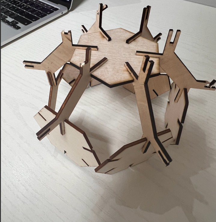
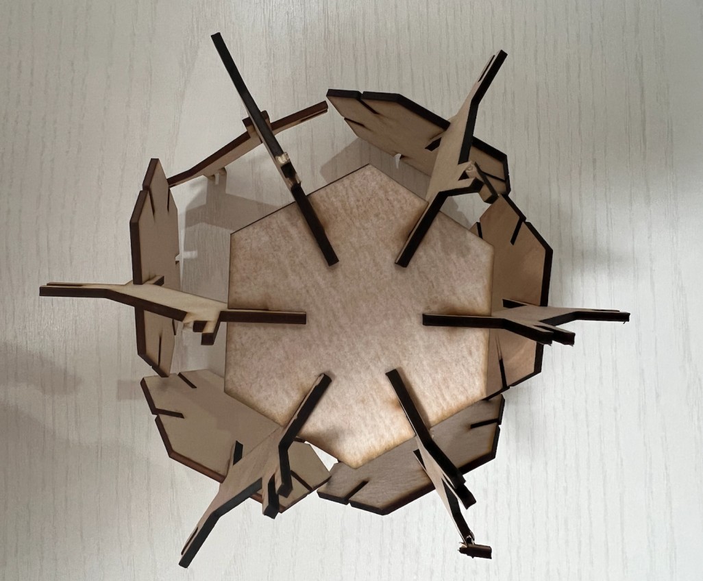
I set up my parameters for w and k for the designs so that the edges would fit together. Then, I made multiple copies for all sides that would constitute my antibody ball.
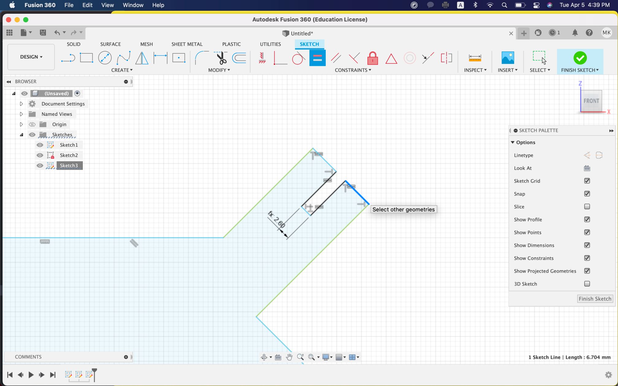 I used circular patterns to create multiple slots equidistantly.
 I then centered after making adjustments to the widths for some components - this ensured alignment.
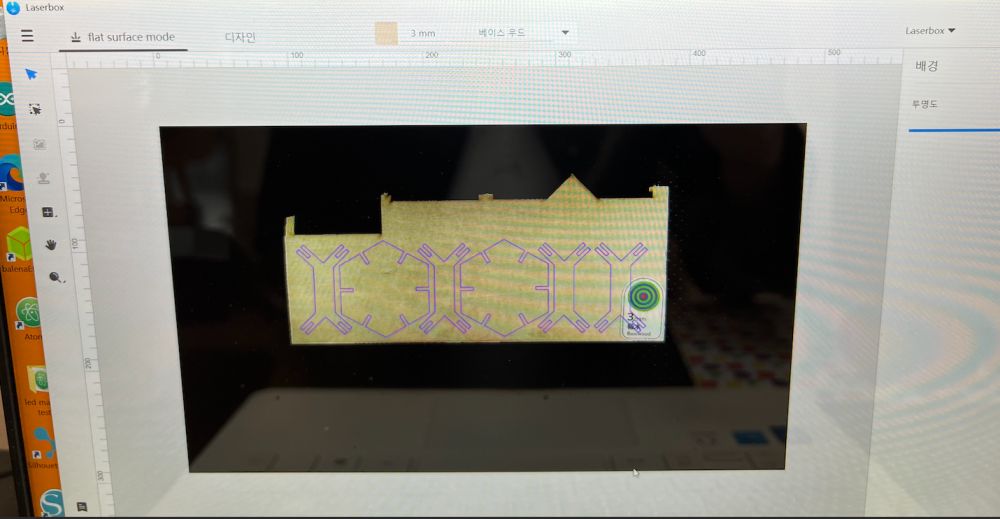
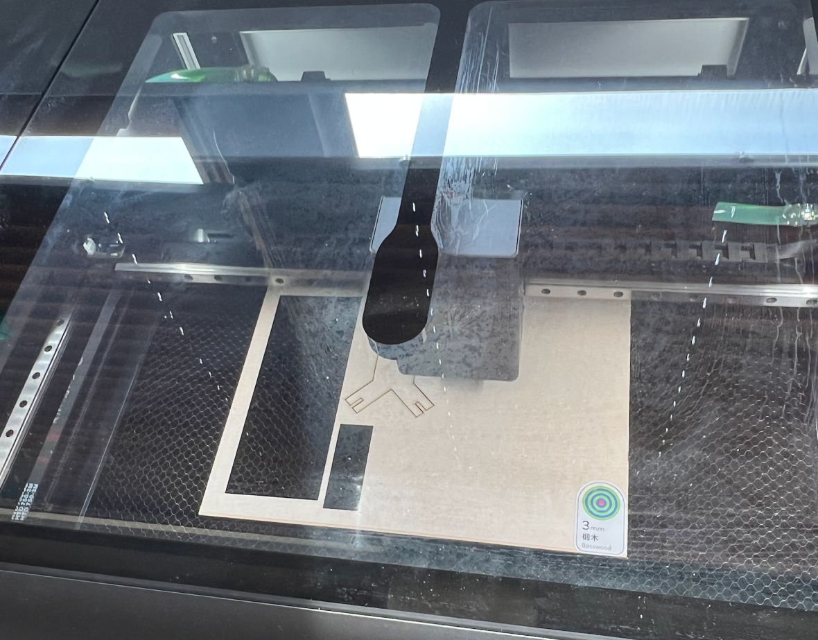
 Here is the laser cutting process!
 At first, the connections/joints were loose because I did w+k*2 which was too large, and I also did not center the slots. Also, after printing, I realized that the tips (dogbone) are too thin, which is likely to break. The slots are also long as well (10 mm), so the tips could generally be wider for future reference.
Here is the link to the file:
https://a360.co/3A8tWCR
At first, the connections/joints were loose because I did w+k*2 which was too large, and I also did not center the slots. Also, after printing, I realized that the tips (dogbone) are too thin, which is likely to break. The slots are also long as well (10 mm), so the tips could generally be wider for future reference.
Here is the link to the file:
https://a360.co/3A8tWCR
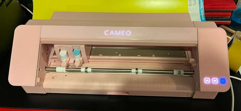
Vinyl Cutter
The vinyl cutter I used at BOLD Lab Seoul was a Silhouette Cameo 4. I never had experience using a vinyl cutter, so I was really excited to use it!
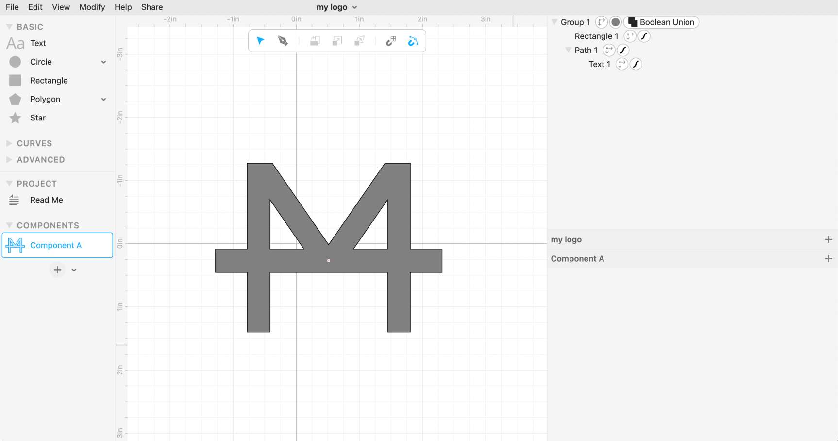
 I used a simple logo design that I created using cuttle.xyz, an online platform. This simple logo was a combination of my initials, MK; I added a text box for the M and added a line in between to create an M horizontally and an inverted K vertically. I used the align and boolean union functions.
 I downloaded the logo as a png file from cuttle and then transferred it to the Silhouette Studio app on my MacBook.
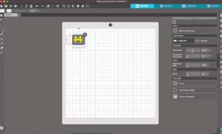
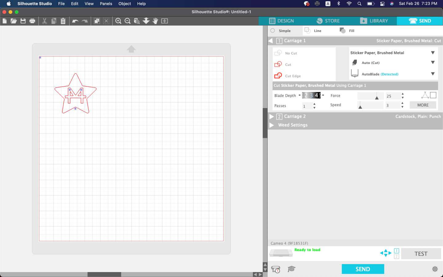
Then, I used the trace function to trace the png file and create a path. I made sure to place the trace accordingly on the grid so that I could print using the vinyl cutter correctly.
 Before sending, I took the protective film off of the mat, which was slightly sticky for the material to stick. I first chose a solid yellow colored materials and stuck it onto the mat.
I turned on the Cameo 4 and then loaded the mat onto the machine by aligning the corners of the mat with the guidelines on the machine. I then pressed the load button on the screen.
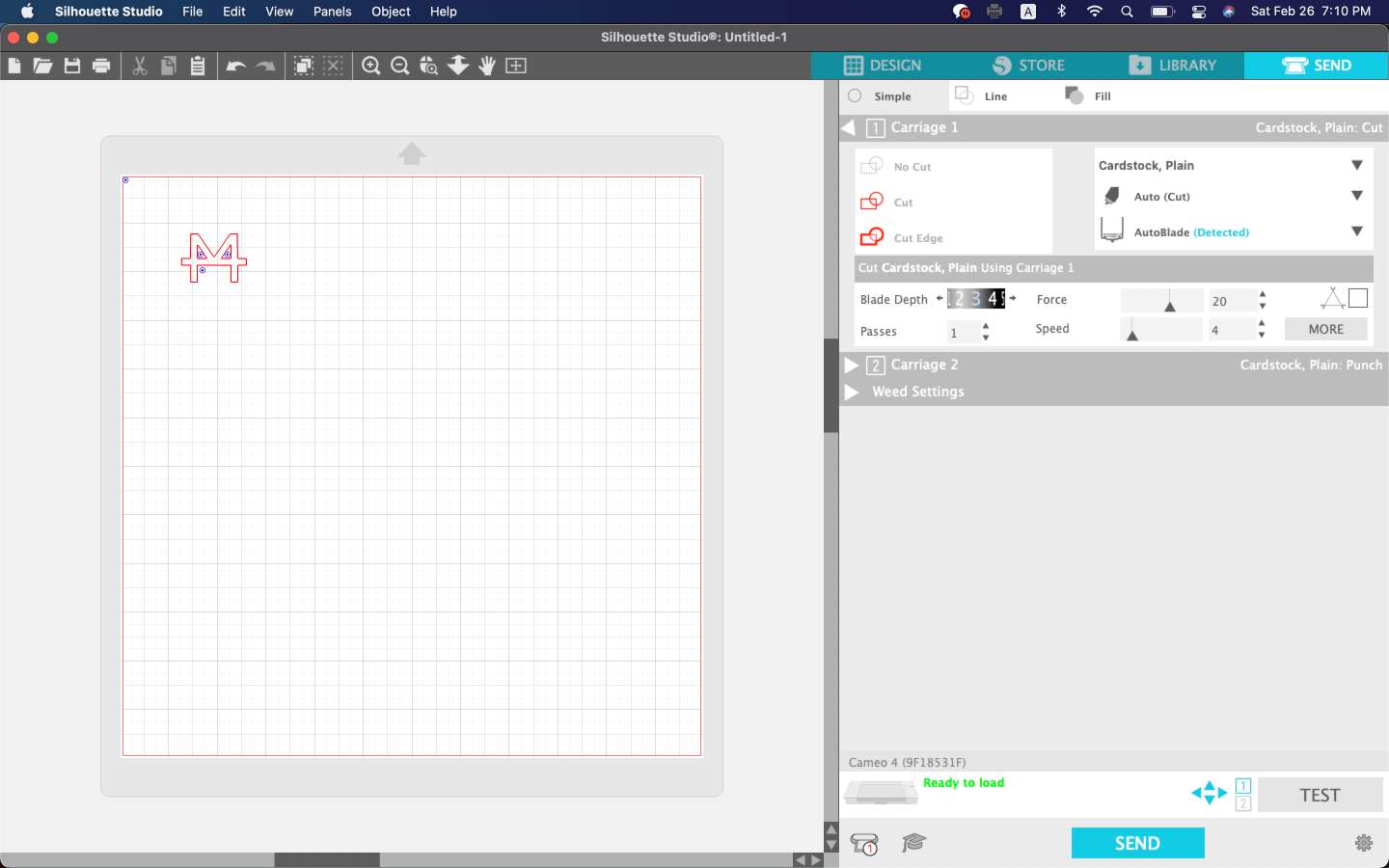
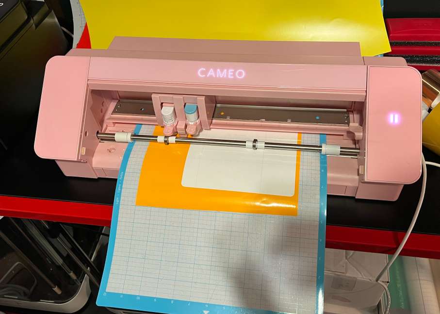 I then sent the trace from the Silhouette Studio app, and the machine started working and cutting.
My first ever vinyl cutting experience turned out successful! I removed the logo and stuck it on my laptop.
 Then, I repeated the same process but added a star around the logo to test out the use of transfer paper. Instead of using transfer paper, however, I used tape since the logo was relatively small.
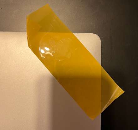
 My initial try was a failure, as the tape was too sticky; I was unable to remove the material from the tape as the tape unfortunately ripped the material…
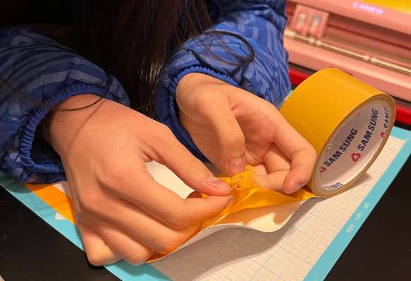
I repeated the same process, but this time used a sparkly/glittery blue material. This time, I reduced the adhesiveness of the tape by sticking it on various surfaces to remove much of the adhesive.
Once the machine cut the material, I added the tape on top of the area in which my logo was printed. Then, I pressed softly to ensure that all parts were fully covered by the tape. Then, I removed the interior with a sharp edge. Finally, I stuck the tape on my laptop, where I wanted to stick the logo onto, and carefully removed the tape.
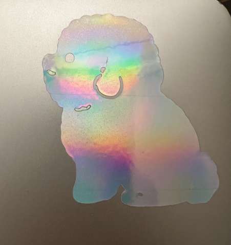
 Finally, I tried cutting a sticker that represented my puppy! I downloaded an image of a puppy online and traced it on Silhouette Studio. When traced, there were 2 paths, so I deleted one path.
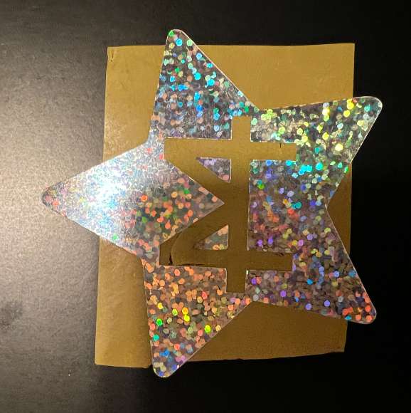
 I used a hologram material, and here is the result! The sticker looks silver, not as reflected as the picture below!
 The link for the file for the sticker is here!
- Sticker
The link for the file for the sticker is here!
- Sticker