14. Networking and Communication
Group Assignment: send a message between two projects
Individual Assignment: design, build, and connect wired or wireless node(s) with network or bus addresses
Wireless Node WIFI Connection
For this week, I had to create a wireless connection using network.
I connected the WIFI to the FTDI and changed the example code on Arduino IDE accordingly after researching online. To create the WIFI module, I used the ESP8266 board, which is a integrated Wi-Fi MCU. The code that I used is shown below.
For this week, I downloaded a new library, Adafruit ESP8266. I went to “tools”, “manage libraries”, and downloaded Adafruit ESP8266 (I could download from the arduino app without having to find a link to download the library).
The tutorial that I used to learn and obtain the code is linked here. - Link
#include <ESP8266WiFi.h>
#include <WiFiClient.h>
//ESP Web Server Library to host a web page
#include <ESP8266WebServer.h>
//---------------------------------------------------------------
//Our HTML webpage contents in program memory
const char MAIN_page[] PROGMEM = R"=====(
<!DOCTYPE html>
<html>
<body>
<center>
<h1>WiFi LED on off demo: 1</h1><br>
Click! to turn <a href="ledOn">LED ON</a><br>
Click! to turn <a href="ledOff">LED OFF</a><br>
<hr>
</center>
</body>
</html>
)=====";
//---------------------------------------------------------------
//On board LED Connected to GPIO2
#define LED 2
//SSID and Password of your WiFi router
const char* ssid = "NAMEOFWIFI";
const char* password = "WIFIPASSWORD";
//Declare a global object variable from the ESP8266WebServer class.
ESP8266WebServer server(80); //Server on port 80
//===============================================================
// This routine is executed when you open its IP in browser
//===============================================================
void handleRoot() {
Serial.println("You called root page");
String s = MAIN_page; //Read HTML contents
server.send(200, "text/html", s); //Send web page
}
void handleLEDon() {
Serial.println("LED on page");
digitalWrite(LED,LOW); //LED is connected in reverse
server.send(200, "text/html", "LED is ON"); //Send ADC value only to client ajax request
}
void handleLEDoff() {
Serial.println("LED off page");
digitalWrite(LED,HIGH); //LED off
server.send(200, "text/html", "LED is OFF"); //Send ADC value only to client ajax request
}
//==============================================================
// SETUP
//==============================================================
void setup(void){
Serial.begin(115200);
WiFi.begin(ssid, password); //Connect to your WiFi router
Serial.println("");
//Onboard LED port Direction output
pinMode(LED,OUTPUT);
//Power on LED state off
digitalWrite(LED,HIGH);
// Wait for connection
while (WiFi.status() != WL_CONNECTED) {
delay(500);
Serial.print(".");
}
//If connection successful show IP address in serial monitor
Serial.println("");
Serial.print("Connected to ");
Serial.println(ssid);
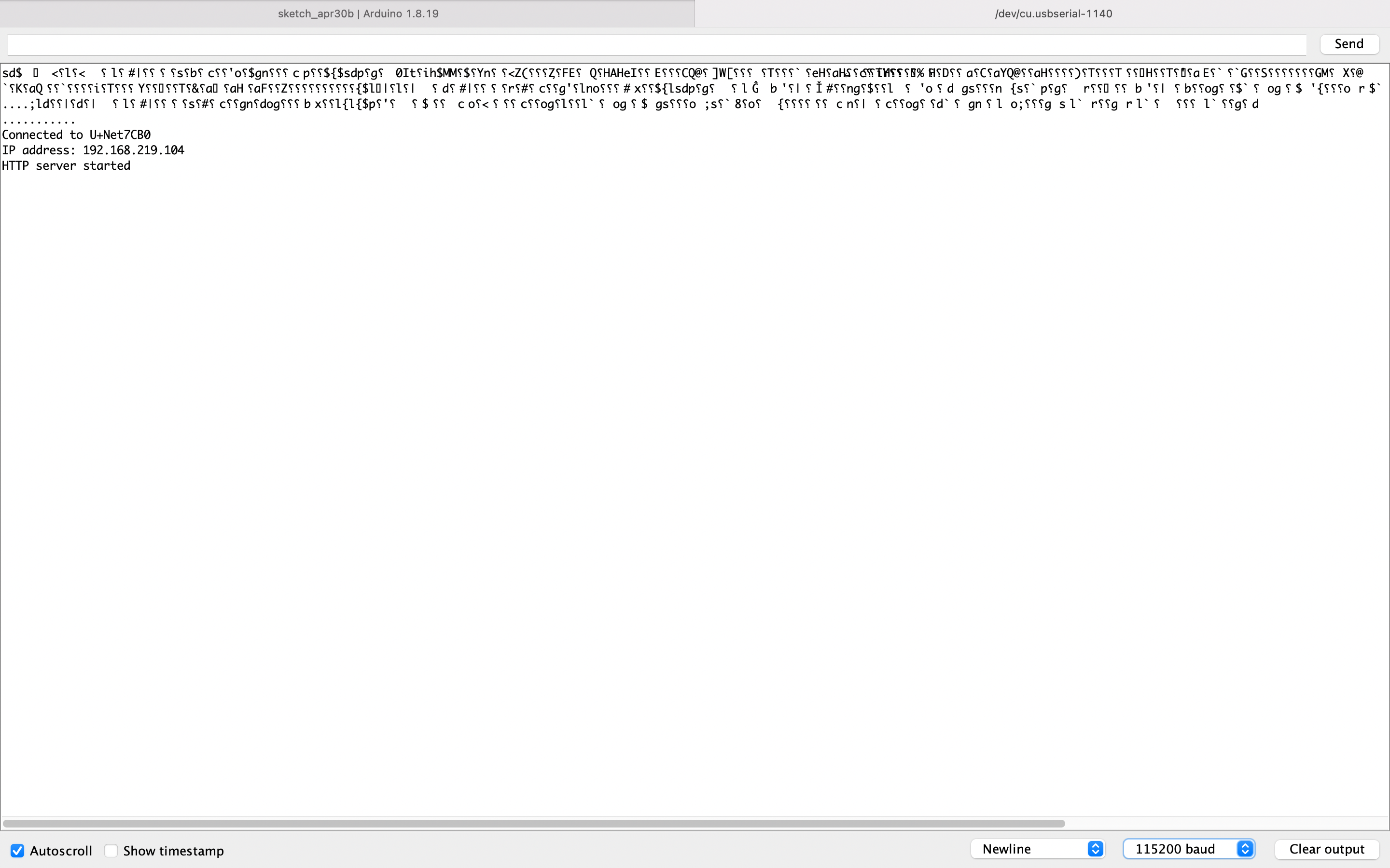
Serial.print("IP address: ");
Serial.println(WiFi.localIP()); //IP address assigned to your ESP
server.on("/", handleRoot); //Which routine to handle at root location. This is display page
server.on("/ledOn", handleLEDon); //as Per <a href="ledOn">, Subroutine to be called
server.on("/ledOff", handleLEDoff);
server.begin(); //Start server
Serial.println("HTTP server started");
}
//==============================================================
// LOOP
//==============================================================
void loop(void){
server.handleClient(); //Handle client requests
}
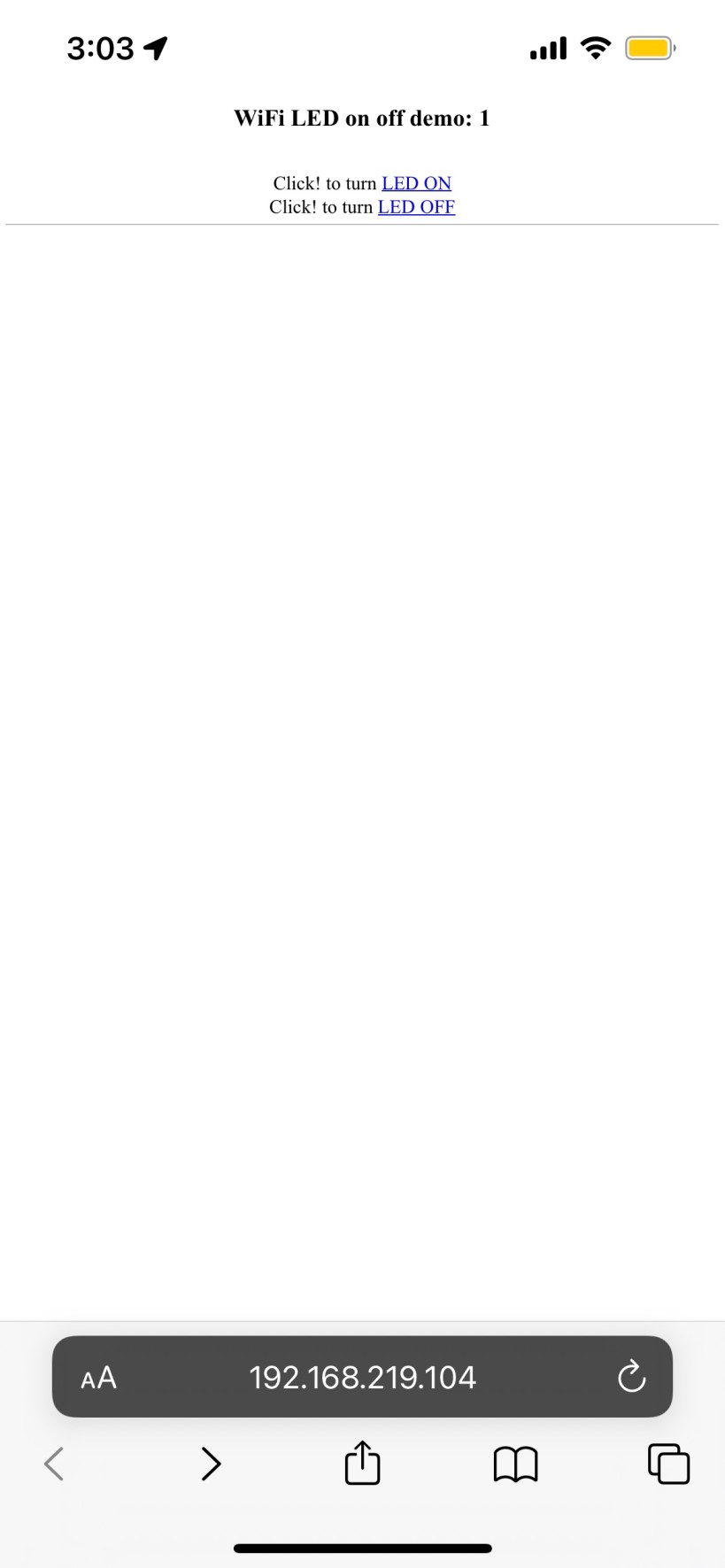
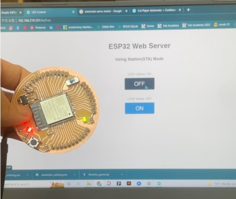
After uploading the code, I was given the IP address that I entered online, which brought me to a page that had clickable links to turn on/off the light!
 I could change the writing on the website, such as “Click!” by altering the written word in the code above. Following the code, clicking on “LED ON” turned the LED on while clicking on “LED OFF” turned the LED off.
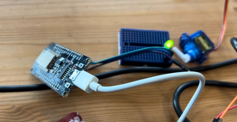
Here is another board (ESP82) using similar programming.
OLED Monitor
To deliver messages, the I2C protocol was use. The I2C protocol, aka Inter-integrated circuit, is a bus interface connection that is incorporated into devices for serial communication. Communication between 2 circuits can be established, and it is a part of the master-slave communication. Moreover, besides being used to connect multiple integrated circuits, I2C connections can be used for communication between integrated circuits that are on the same PCB.
For I2C communication, low speed application is recommended. The advantages pf using I2C communication is that the multi-master and multi-slave component allows various functions to be performed, and the simple signal lines to create connections between integrsted circuits, along with a low pin count, results in a simpler form of communication and connection.
Since the initiation of the communication comes from the master, the Serial Data wire (SDW) is then used for data transfer between master and slave.
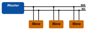 The picture above was brought from this website. More information about I2C connections can also be found here.
- Link
In order to use I2C communication for this week, I downloaded the Adafruit library online and loaded it on Arduino IDE by obtaining appropriate links for library searches on the internet. The OLED I2C tutorial that I followed, as well as the code, was from this link.
- Link
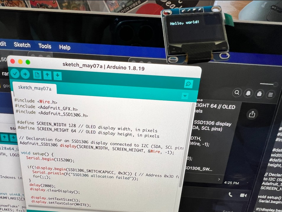
The code that I used for I2C programming is shown below. To change what you want to display on the OLED screen, simply change the phrase written inside the quotation marks in this part of the code: display.println(“Hello, world!”);
The picture above was brought from this website. More information about I2C connections can also be found here.
- Link
In order to use I2C communication for this week, I downloaded the Adafruit library online and loaded it on Arduino IDE by obtaining appropriate links for library searches on the internet. The OLED I2C tutorial that I followed, as well as the code, was from this link.
- Link
The code that I used for I2C programming is shown below. To change what you want to display on the OLED screen, simply change the phrase written inside the quotation marks in this part of the code: display.println(“Hello, world!”);
Since mine reads Hello, world!, the display will show up as Hello, world!, but can be changed to other phrases if modified.
#include <Wire.h>
#include <Adafruit_GFX.h>
#include <Adafruit_SSD1306.h>

#define SCREEN_WIDTH 128 // OLED display width, in pixels
#define SCREEN_HEIGHT 64 // OLED display height, in pixels

// Declaration for an SSD1306 display connected to I2C (SDA, SCL pins)
Adafruit_SSD1306 display(SCREEN_WIDTH, SCREEN_HEIGHT, &Wire, -1);

void setup() {
  Serial.begin(115200);

  if(!display.begin(SSD1306_SWITCHCAPVCC, 0x3C)) { // Address 0x3D for 128x64
    Serial.println(F("SSD1306 allocation failed"));
    for(;;);
  }
  delay(2000);
  display.clearDisplay();

  display.setTextSize(1);
  display.setTextColor(WHITE);
  display.setCursor(0, 10);
  // Display static text
  display.println("Hello, world!");
  display.display();
}

void loop() {

}