Week 09: Mechanical design, machine design
Assignments:
Mechanical Design (part 1 of 2):
-
Group assignment: Design a machine that includes mechanism + actuation + automation. Build the mechanical parts and operate it manually. Document the group project
-
Individual assignment: Document your individual contribution.
Basically the first part of the assignment is about thinking what our machine is going to do and design its mechanism. Work the machine without motors.
Machine Design (part 2 of 2):
-
Group assignment: Actuate and automate your machine. Document the group project.
-
Individual assignment: Document your individual contribution.
What to learn:
-
Work and communicate effectively in a team and independently
-
Design, plan and build a system
-
Analyse and solve technical problems
-
Recognise opportunities for improvements in the design
Have you?
-
Documented the machine building process to the group page
-
Documented your individual contribution to this project on your own website
-
Linked to the group page from your individual page as well as from group page to your individual pages
-
Shown how your team planned and executed the project (Group page)
-
Described problems and how the team solved them (Group page)
-
Listed future development opportunities for this project (Group page)
-
Included your design files (Group page)
-
Optionally included an aprox. 1 min video (1920x1080 HTML5 MP4) + slide (1920x1080 PNG) (Group page)
DOUBT: Do we have to design new boards for this? Answer: No. You can use the gestalt or other existing commercial boards.
DOUBT: I’m the only student in the lab, can I complete the assignment by building the machine alone? Answer: No. You need to collaborate with someone. This is a team effort.
DOUBT: What is the recommended size of the team? Answer: Optimal size of the group is three to five students per machine building project.
DOUBT: Can we use off-the-shelf software? Answer: Yes.
MECHANICAL DESIGN NOTES:
Mechanical design is the design of the elements(components/ parts/ systems) of a machine, like for example shafts, bearings, gears, and fasteners. This is a very handy book on mechanical design, which explains the different basic elements and properties for mechanical design.
Vendors for mechanical parts:
-
Amazon Industrial: has bought to other vendors.
-
Misumi: has a number of industrial product.
Principles for mechanical design:
Stress-strain: in this link it explains how to calculate stress-strain.
-
Stress: is the measure of internal resistance in a body when an external force is applied to it.
-
Strain: is the measure of deformation in a material when stress is applied to it.
Stiffness vs Strength vs Hardness are related properties but have differences between them:
-
Stiffness: is the tendency for an element to return to its original form after having a force applied to it.
-
Strength: measures how much stress can be applied to a body before it deforms permanently.
-
Hardness: measures a material’s resistance to surface deformation, we want to stay in the elastic limit.
-
Moduli: measures the resistance of the material to elastic—or “springy”—deformation.
-
Friction: force that resists the sliding or of one solid object over another.
-
Spalling: the flakes that are separated from a larger body of material (due to corrosion, weathering, friction, etc).
-
Hysteresis: deadzones in the coupling between 2 variables, it is one of the worst things for the machine because you want to come back where you started from. I tried to understand this term through this link. Coupling: A coupling is a device used to connect two shafts together at their ends for the purpose of transmitting power. The primary purpose of couplings is to join two pieces of rotating equipment while permitting some degree of misalignment or end movement or both.
-
Force loops: “Motors contain loops of wire in a magnetic field. When current is passed through the loops, the magnetic field exerts torque on the loops, which rotates a shaft. Electrical energy is converted into mechanical work in the process.” Explanation from here
-
Elastic averaging: if you over constrain a tool you reduce the error
Materials for mechanical parts:
-
Plastic: we use high density polyethylene, good structural properties for a machine. HTPE.
-
Metal sheets to do stiffer machines.
-
Rubber: to be dissipative, to absorb vibrations in machines.
-
Garolite: it is a natural fibre composite, you can machine it, allows you to make really stiff material parts, but it is easier to use.
-
Wood: it is used in beginner machine building, but it is not really recommended because it changes over time, humidity, etc.
-
Cement: good working properties.
-
Ceramic: for parts of the machines where you need hardness (not stiffness).
-
Cardboard: cheap machine building, quick easy way to prototype a machine.
Adhesives for mechanical parts:
Fasteners to join 2 or more mechanical parts:
-
Washers: very important.
-
Heat-set inserts: to spread the load from the head of the bolt or it will deform the material.
-
Rivets: irreversible but it is a handy way of joining things.
-
Pins: multiple uses, to hold things from flipping away from the pins.
Framing your machine
-
Metal extrusion: for example in the Shopbot the structural beams are metal extrusions, they vary in sizes, stiffnesses, …
-
Plastic: you can also get plastic extrusion.
-
T-slot: to join parts of the machine together.
How to drive the mechanical parts?
-
Planetary: Pair these speed reducers with stepper and servo motors in position- and speed-control applications.
How to guide the movements of the mechanical parts?
Couplers: element that transmits power between two rotating mechanisms or a rotating part and a reciprocating part
-
Shafts: your motor might not be exactly aligned with machine, these are designed to be very stiff
Bearings: to allow surfaces to roll to each other
-
Linear: that move along a shaft.
-
Pillow blocks: mounted.
Rotary elements to move mechanical parts:
Lubricants for mechanical parts:
- Different types:. “Machine reliability relies on the right methods of lubrication, the right quantities and formulations of lubrication and the appropriate application procedures and intervals – and a vigilant machinery operator will be able to maximise the performance and the operating life of the equipment by adhering to a well-planned and appropriate maintenance programme.” -Source
To organise/attach cables:
To pass through liquids:
Conveyors to move objects around:
Springs: to load things against backlash so that the motor is pushing against the spring. They are used when wanted to make elastic joints.
Different types of mechanisms:
-
Flexure: check page 45, this is shown in the following link, Stage:
-
Linkage: whole library which shows different types of mechanisms of how to connect one kind of motion in one direction to another type of motion in another direction
-
Whippletree: adds forces while allowing its position to change
-
Deltabot: some kind od 3D printing geometry.
-
Hexapod: multi-axis systems because they allow a user-defined center of rotation, or pivot point, for all six axes of motion.
-
CoreXY: neat mechanism based on stationery motors
-
Hoberman: master of mechanism, architectural scale, whole buildings with these sort of mechanisms. They specialise in transformable design—the design and development of products, structures, and environments that change their size and shape. Amazing!
-
Strandbeest: inventor of mechanisms to make creatures that move, very creative!
Basically the first part of the assignment is about thinking what our machine is going to do and design its mechanism. Work the machine without motors.
MACHINE DESIGN NOTES
Machine example projects:
-
This example which is also explained in this video also shows how to build different machines by having individual motion axis which can be assembled in different ways.
-
This essay by Nadya Peek talks about how we should build machines that build machines.
-
Link to structural loop and error budget guidelines for effective machine building.
Aspects of machines:
- End effectors: are what goes on the machine to do something. This project called POP FABLAB shows it perfectly.
For this week we will be given motor controllers but in the coming weeks we will learn how to actually make motor controllers. In the following weeks we will also learn further in aspects that can also be integrated within machine building:
-
Power electronics(special components to switch power): in the fab inventory from Digi-key we have power transistors(which let us switch large current and voltages) and we also have motor drivers (h-bridges and triple half bridges)
-
Real-time networks: wired and wireless networks which let us communicate easy at megabit data rate between processors, huge change in machine building because it has allowed machines to not have to have a controller which controls its axis and motors but rather these being connected and communicate by networks.
-
Motor control is moving a motor.
-
Motion control is moving multiple motors to solve a problem. These have control loops which can be open: to send a command to motor and it makes steps, or closed: you send a position and it uses feedback to do it, for example it will tell you if you are cutting too deep or too fast.
-
You need a path for the machine and these can be static or dynamic which means you have to plan the path taking into consideration the deformation of the tool.
-
Control theory: turning things on and off is a terrible idea you need some time of current control to move the motors smoothly(motion control). There are various types: bang-bang(on off, terrible idea, you need some control to move it smoothly), PID acceleration(analog), model predictive (you use a model of the machine), online optimization. Bible to control theory.
-
Timing, if we have a machine with 3 axis and 3 motors and we want to move them you need to coordinate the motion of all of them. Framework from Nadya and Alan developed as an example. One way to do it is handshaking(a line that goes to the all the motors and each motor tell you what is done), broadcasting(tell all the motors go now and then you tell them stop), time-stamp(you send a bunch of messages to motors in advance to tell them what to do at certain time), back-pressure(you send messages out and motors pull messages when they are done with the job).
-
Machine control: this framework lets you build virtual machines, thesis on dataflow, building parts of the machine with a timing belt. In software making graph of the logic of the machine, like MODS but for machine control, software graph talking machine graph used to move machine,
-
File formats: to communicate with the machine, g-code is a standard format, G-code to machine and machine will interpret it. You don’t need this if you are making a real time machine network. This is a classic interpreter, takes g-code in and has motors controllers out, uses this to run machine. The problem is that inside the interpreter it has to know the axis, step, everything about the machine,.. and if you change anything on the machine you have to change everything inside the TinyG. By eliminating these and using the machine network you just have to change the software driving the machine but not the configuration inside the machine.
-
User interface: one step further is building a user interface. Classic user interface
-
Path planning: we have been using MODS, mods has a series of modules, when you read the image, you can open each of these and read the code in each module to see what they are doing, you need something like this, you can use MODS or you can build one from scratch.
-
Design representation: functional are much more powerful ways to represent a design.
Interesting vendors:
-
OpenBuilds: sells all the things you need for parts of the machine +
-
RobotShop: has all kinds of parts for robots
-
Pololu: vendor that makes little kits for electronics, in particular they have motor controls with reasonable prices to assemble machine control
-
Synthetos: combine g-code interpretation with motor control (more expensive)
Motor vendors:
-
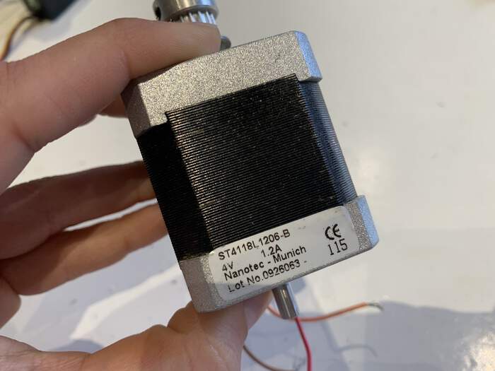
Stepper Online: for the stepper you care about the step angle, the holding torque is the force beyong you will beat the motor, the current and voltage to drive it.
-
Just Motion Control: it is very cheap to order custom projects.
-
Oriental Motors it is quite cheap to order custom motors
Basically the second part of the assignment is about putting into motion the moving parts and automate these movements too
STARTING GROUP PROJECT
The three parts to this machine design assignment are:
-
To have moving parts in the machine (part 1)
-
These moving parts have to have actuation which means to put into motion something (move the moving parts), this does not mean it necessarily needs a motor. (part 2)
-
The machine has to have some control of automation automated which means you have to reduce human intervention to make these moving parts actually move. (part 2)
Types of motors:
Nearly all mechanical developments have an electric motor. Electric motors make the machine do something (machines can also move without an electric motor). This week our assignment is to create a machine with moving parts. Motors take electrical energy and produce mechanical movements. On Friday we were introduced to different electric motors:
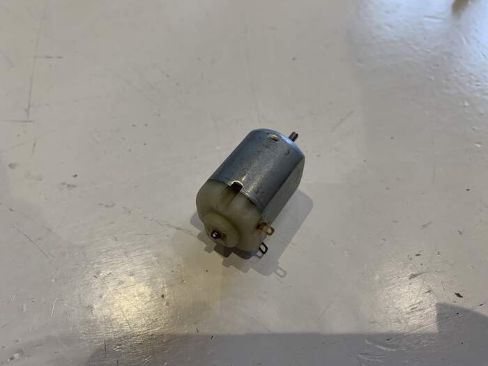
Dc motor: it has two legs.
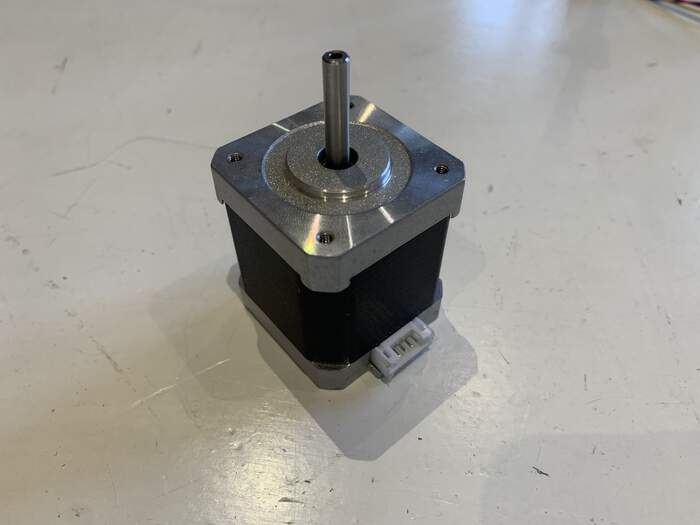
Stepper motors: are usually used in automation systems. We were introduced to the Nema17 which goes in steps of 1.8 degrees, to make a complete rotation (360 degrees) it would take 200 steps. The shaft connected to the rod can turn clockwise or counterclockwise. If you do PWM (Pulse Width Modulation = controls the amount of motor) the motor can do 32 micro steps within each step (microstepping) which would be 6400 steps/circle.
-
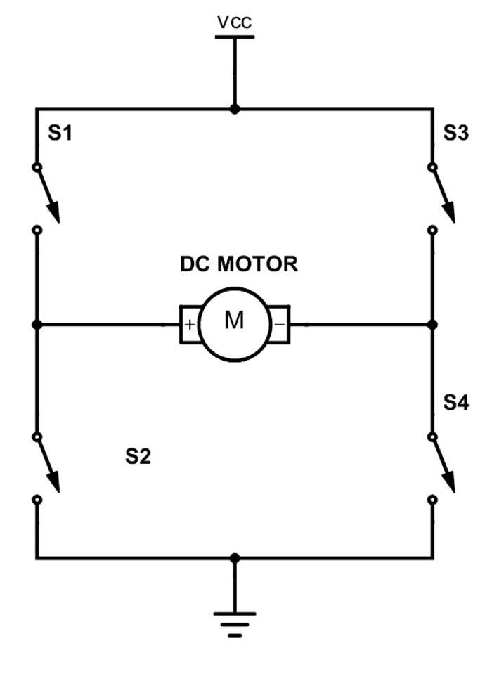
These motors require drivers or controllers so that they work. In order for them to work with a micro-controller, they also need a h-bridge. The h-bridge (which are connected to the Arduino) controls VCC and GND(they can be turned around so that the shaft can turn clockwise or anticlockwise) and the amount of current(stepping). I found a very useful link which explains the h-bridge. “The h-bridge is a simple circuit that lets you control a DC motor to go backward or forward. Your normally use it with a microcontroller, such as an Arduino, to control motors. When you can control two motors to go either forward or backward – you can build yourself a robot!”
-
Here’s is the simple circuit H-bridge:
-
“A DC motor spins either backward or forward, depending on how you connect the plus and the minus. If you close switch 1 and 4, you have plus connected to the left side of the motor and minus to the other side. And the motor will start spinning in one direction.”
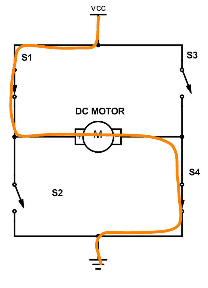
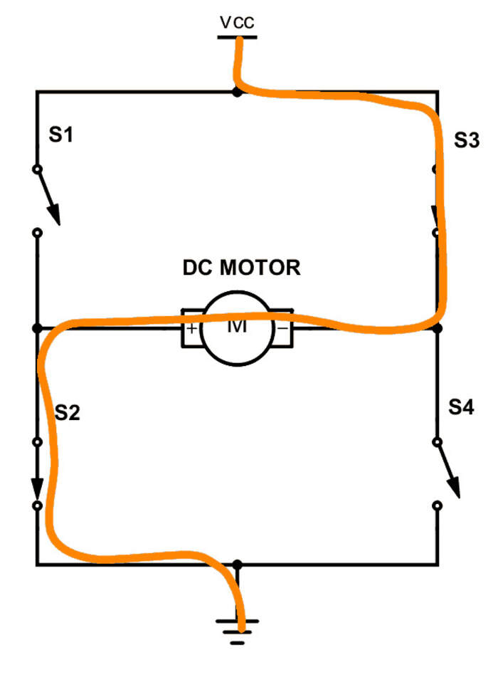
-
“If you instead close switch 2 and 3, you have plus connected to the right side and minus to the left side. And the motor spins in the opposite direction.”
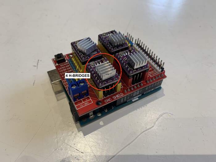
-
These h-bridges(ICs) are placed in the CNC shield for the Arduino with a fan as they handle 12V and they get heated up quite quickly. The CNC shield has four connections for stepper motors.
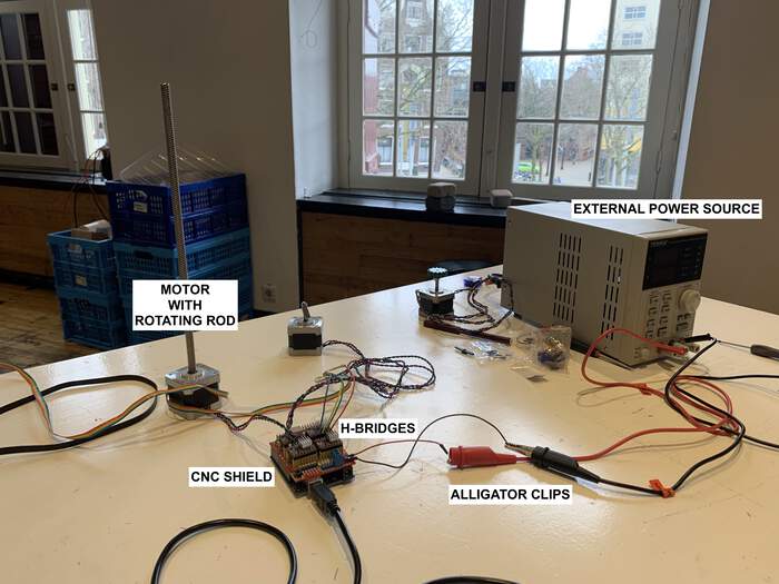
-
Henk did a small introduction of how to connect the CNC shield to a power external source which made the motor move!
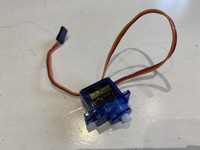
Servo motors:
-
This is a small servo motor of 180 degree, 100 steps.
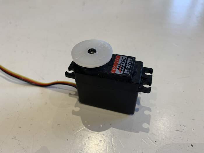
-
This is also a bigger servo motor which has more force:
If we are going to make something we have to keep in mind we need a power source, different power sources or a power source that can be regulated.
First machine brainstorming: pros and cons of ideas
PANCAKE MAKER: Pros: - very nice to have it and eat them - dutch culture
Cons: - it has to flip, heat, pour, too many movements for the time constraints we have. - heat problem, it might melt - material properties can be difficult to avoid food poisoning - end of process = undefined, if we don’t finish it we will have just bits and pieces.
TOFU/ CHEESE PRESSOR: Pros: - it is very makeable - it is quite simple, not a lot of machine process
Cons: - Supports have to be strong, how do you handle pressure?
M&M SORTING: Pros: - Can be used for easter eggs (color)/ chewing gums/ knickerballs = different disk size depending in what you are putting in it. - Sorting colors -> move on a track/ swirl (inspiration Didi Vardi) before it goes to you - It is very compartimental, everyone can work on a part. - Quite duable and manageable for the amount of time we have.
Cons: - Nice but useless - It is not very original because there has been other projects with similar mechanisms.
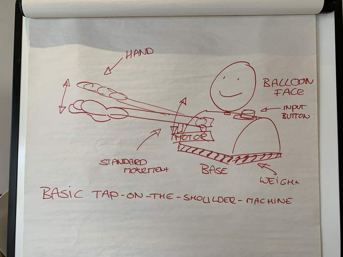
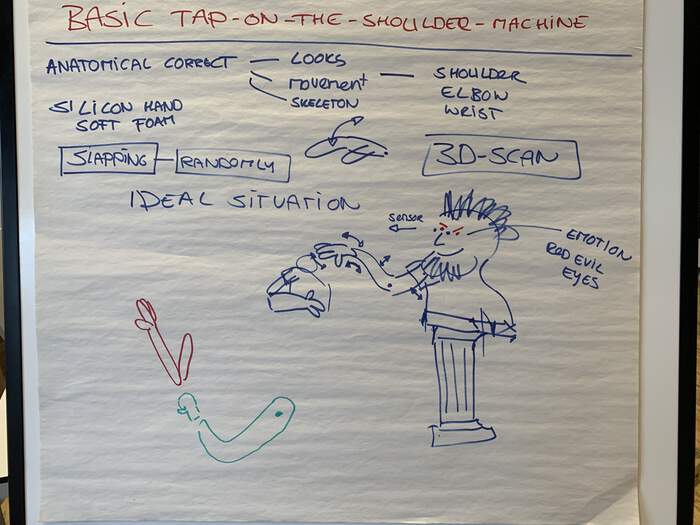
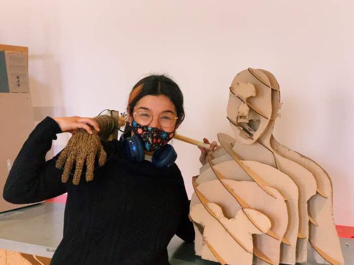
PATTING MACHINE:
This machine is about making a machine with Henks’ appearance (our tutor) which pats you in the shoulder for work motivation in those stress times everyone has in the FabAcademy.
Pros: - Makes you smile
Cons: - Useless.
Second machine brainstorming: deciding on an idea and starting to brainstorm for it
We finally decided for the patting machine as we thought is was not the cartesian(x, y, z axis which you normally imagine as a machine). We started encountering different questions and challenges:
-
¿2D or 3D? We could scan Henk or look for sites that make a a 3D from a 2D image.
-
Make it very simple, very mechanical, and then add complexity with different types fo sensors(speed of patting,… from pat or spat, height of the person to pat correctly,…we could even add sound output with very simple sound devices that you can send output 1, 2, 3, …
-
The first arm mechanism we thought of was an arm coming down, when it touches shoulder and feels resistance, it will start the patting just like the Prusa motor
-
How heavy it is going to be, how much force we need to lift it? How powerful is the gear we have?
-
The first spiral we designed for the mechanism of the arm was something like this: First arm moves up and down, second it can move up and down, moves wrist (pulses for the patting), third; the wrist can rotate.
-
Hand and arm different material so that the hand is lighter?
-
Arm can be done in slices to add the anatomical look.
Third machine brainstorming: looking at some inspiration projects
Some of the inspiration projects I looked initially for the arm and hand were:
-
This example which gave us the idea of connecting the motor to strings which would then move the arm parts.
-
This arm example shows an arm done with four degrees of freedom which was kind of what we had been talking about.
-
This paper mache structure opened the option of making the whole structure of this to make the arm as light as possible (because the motor was already going to be most of the weight).
-
This hand project seems far too complicated but I like the idea of 3D printing hand parts which we could flexibly attach somehow? so that the hand “adapts to the shoulder when patting”.
-
This example shows how we could also mould the hand with silicone, but we decided that with the time constraints we have this takes too long.
-
This hand project shows a cardboard hand with movement.
Fourth machine brainstorming: motors and electronics
We also talked about that if we wanted the wrist to move, the moving parts should as precise as possible. For this there were two options:
-
Wrist motor in wrist or in elbow? or in shoulder?
-
Arm with springloaded (makes hand wobbly, minimizes direct contact, motors on/off)
Options for motors: - A DC motor expects an h-bridge, motor is fixed, nut moves the rotation makes the arm move. This is a very nice intro into the different motors and how to control them.
-
Steppers: A stepper expects steps (a bit-pattern)
-
A servo expects a voltage level (or pwm (analogWrite) output).
For the electronics Erwin initially said we did not need any fancy electronics that we did not have at den Waag so this was good. We also had to thought of sensors/ switches to make the hand pat the shoulder.
Fifth machine brainstorming: basic product and product without limits
To clearly delimitate our project we did two lists:
The first list is the basic product list with very basic input and output, two motors and one button.
-
Structure with an arm which moves up and down with a motor from the shoulder, lower it, when it reached resistance, wrist starts moving through a second motor.
-
Input: tap him on the shoulder (button) for the arm to move
-
It has a mechanism to move arm, our main inspiration for the mechanism is this lamp mechanism at out lab:
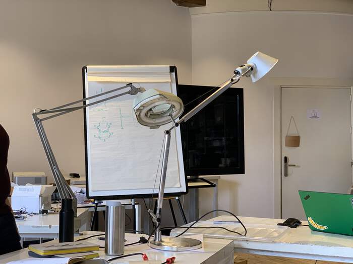
- The arm sticks out.
The end product without limits is a list of things we could add spirally once our basic product is done:
-
Arm anatomically looking good but also move it anatomically.
-
Have a shoulder, elbow, wrist.
-
Have a soft hand, foam? silicon hand?
-
3D scan of head + body
-
Where is the starting point of arm? resting? up? Safety wise it is better that the arm comes down.
-
Option of slapping (rotating wrist)
-
Sensors: red light eyes when slapping
After this realistic vs utopian list of the design of our machine we decided for spirals option 2: OPTION 1:
-
SPIRAL #1 Arm with a flexible structure that can move up and down.
-
SPIRAL #2 The same flexible arm structure that can extend up and out.
OPTION 2:
-
SPIRAL #1 The same flexible arm structure that can extend up and out
-
SPIRAL #2 wrist moves up and down
Sixth machine brainstorming: dividing tasks
Our machine has basically 4 parts which we divided into the four of us and some extra ideas we added:
-
HAND and WRIST: (Phil)
-
Casting of the hand and mechanism of the wrist.
-
3D printed hinges to join the parts?
-
ARM: (Lucia)
-
Mechanism of moving arm.
-
How fast can the motor go and how much strength does it have?
-
TORSO + HEAD: (Paula)
-
Make the torso and head of model, sturdy enough to handle the weight.
-
Give it an anatomic look
-
Possibility of attaching motors or storing cables from arm
-
Give an anatomic look to the arm too.
-
ELECTRONICS: keep them all in the same part of the structure. (Erwin)
-
Software-programming: steppers, motors, tasks, and how they are programmed. Motor on the arm somewhere. Motors + electronics.
STARTING INDIVIDUAL PART OF GROUP PROJECT:
Open day session
Before starting with my machine assignment planning I attended the saturday open day with Lucia and we got really helpful notes:
-
Search datasheet of motors to check the force.
-
The lighter we make the arm, the faster it can go.
-
Wood and paper mache are good materials for what we want.
-
Talk to Cecilia in textile lab for this type of hand
-
Adrian showed us a gripper with soft robotics
-
Usually servo motors are used for robotics instead of stepper motors with the highest torque possible
-
For automation we can use n stops or sensors to stop at a certain point.
-
I also learned that cartesian machines have x, y, z axis (or more) and non cartesian machines don’t have axis, they are more lyrical machines like for example a hand that waves.
First brainstorming: What do I have to do?
When we divided the parts I was assigned the task to make the torso and head of our machine. I don’t have much experience in casting hands/ electronics/ motors or structure building, apart from previous assignments so I really did not have a preference, everything would be a new world for me to discover. I knew the structure had to:
-
be sturdy enough so that it would not fall sideways of forwards when the hand moved.
-
it also had to have some sort of openings for cables to pass through and the possibility to place the axes and motor within the torso and not within the arm (we are still deciding on this). I will work closely with Lucia as she is in charge of the arm and also with Erwin as he is the electronics guy of the group. Philip will be doing the hand and I will have to check if any cable have to be stored within the torso too.
The questions that arised within my task development were:
-
How to make the structure in order to store cables and axes if necessary?
-
What material suits best to make it sturdy enough to handle all the weight?
-
How to move the mouth? In case we want our mouth to move up and down there has to be flexibility enough within the head structure (further spirals)
In the following first draft I try to look for solutions for the three of them:
TORSO MATERIAL AND STRUCTURE IDEAS: 1. Wood - 3D Multi Layered; it is robust enough, we would have to add weight somehow. It gives the option of inserting an axis structure within the different layers (by leaving spaces). The inspiration for this type of structure came from this shape
- Wood - 3D model (we can download them from Thingiverse) -> to sliced layers which can be cut in the laser cut. This can be done with the slicer tool: https://www.youtube.com/watch?v=a1MKnQkca3Y&ab_channel=JoelHall
My main inspiration also comes from this image I found from a robot made in Tokyo for retail called D+ropop, I am still working in all the details but I think it is a good idea as we can make the holes for axes/ cables we want, depending on what we decide in the end, so it is quite flexible. I am still thinking how to make it sturdy enough (also important to know how heavy the arm will be too). This is also a similar example of what I was planning to have.
I also looked into Lorena’s project of cutting on CNC a wooden human model which helped me a lot in the development of my individual task.
How many mm of wood thickness? 15 mm birch plywood is was Lorena used and it looks quite sturdy and it holds her mannequin so it should work. I will probably go between 12-15mm.
Wood type? - Plywood?
-
Medium Density Fiberboard (MDF)
-
Medium Density Overlay (MDO)
-
Oriented Strand Board (OSB) finishing
Machine? CNC if the wood is this thick.
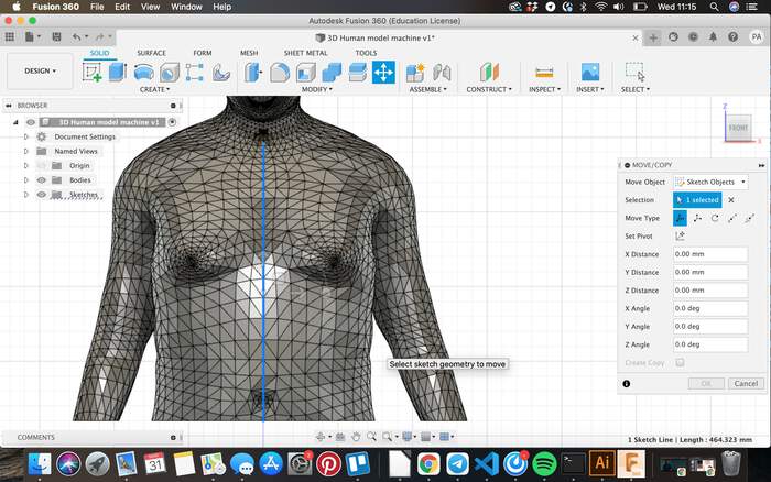
How to make 3D models of a human body? - From Lorena’s documentation I learned how to make human models through this software. Here.
- I also found some already 3D model done for full body and head and torso shape in case the software did not work.
HEAD MATERIAL AND STRUCTURE IDEAS:
I gave up on the idea of having a 3D model of the head with casting and moulding as it would not have the flexibility to allow us to move the mouth if we wanted in the future. Some ideas I found were this one in Instructables. I also found model heads in thingiverse like this one and this one. This example also shows the possibility of making an opening-closing mouth which then made me think of the muppet mechanism which could be an option to further develop this.
Wood type? Plywood? Wood thickness 9mm? Machine? Laser cut or CNC (depending on the wood thickness)
Group dependencies: what do I depend on from the rest of my group mates?
| Group dependencies | What | Description |
|---|---|---|
| Arm/ wrist electronics | Location and size of motors | Depending on the number of motors and their location I should make more or less spaces for them to be placed. |
| Arm | Measurement of the start of the arm (shoulder). Diameter of wires being used move the arm. Weight of the whole arm. | I will need to know the diameter of the arm as well to create the arm hinge which will attach the arm to the torso, as well as the diameter of the different wires passing through it (in case they need to be attached to the torso). |
| Hand | Weight of the hand. Location and size of motors and wires((in case the wires have to be allocated in the torso) | It is important to know the weight to know if the torso structure will be sturdy enough to hold it. |
Things yet to solve:
How to modify the slices depending on the axes/ cable holes, cause the motor might be placed inside the torso with a shaft across it to move the arm?:
How to calculate the weight necessary for it not to fall?
How will the arm be attached to the torso? Design hinges.
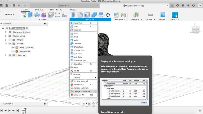
How do I make the whole body parametric?
Working on project (Tuesday)
Today I will meet Philip and Lucia at den Waag and I will try to discuss the following points:
-
Explain the different options of my proposals and go for one.
-
Solve Arm-Torso hinges
-
Choose location of motors
-
See how to calculate the weight necessary for it not to fall?
-
Try different materials to choose the right one.
-
Make a plan of all the things I have to do and plan the week
Where should we place the motors?
-
Choosing from pivoting arm and pivoting elbow.
-
With the pivoting elbow we can spiral to move elbow-wrist-arm, with the other one we can only have two spirals: arm and wrist. The motor in the elbow is less weight of movement.
Weight?
- Weight will be practice driven we will have to see when we build it up.
Hinges?
- Make opening of shoulder parametric! So we can adjust different hinges to it?
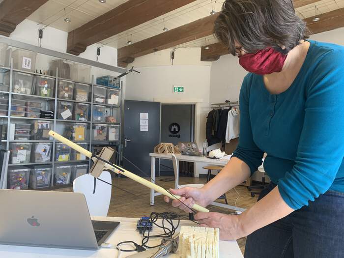
First tryout of anatomical arm:
Make a 3D model of an arm so we can try out different things out with Slicer.
-
I downloaded Make Human from here. This software is to model, configure postures and render human figures of various characteristics, ages and gender.
-
I ran into the following issue and solved it as explained on the downloading website: “The first issue you are likely to run into, is that you might get an error message saying the application cannot be scanned for malicious software. This is because it isn’t signed with a commercial certificate (which we don’t have since we’re a volunteer project without much of a budget). To get around this, see this very helpful link.
-
I started modifying the human model in MakeHuman:
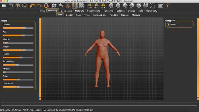
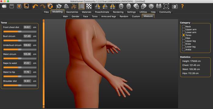
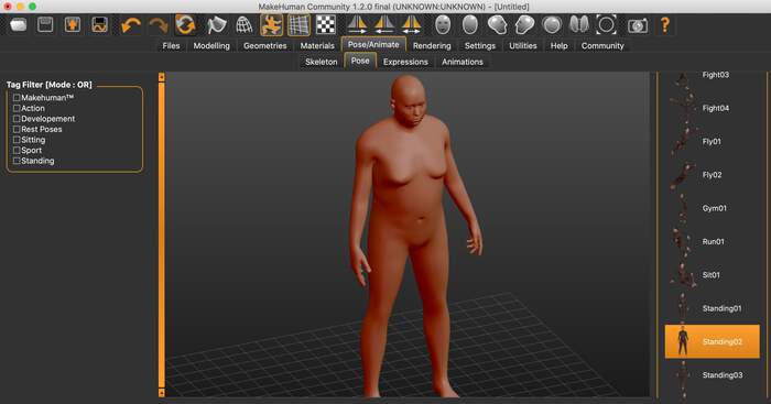
-
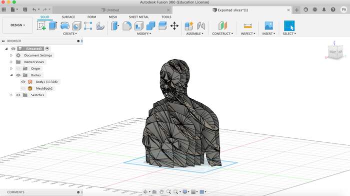
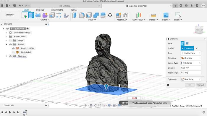
I then exported it as obj and imported it into Fusion360.
-
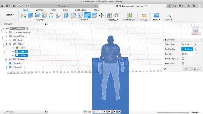
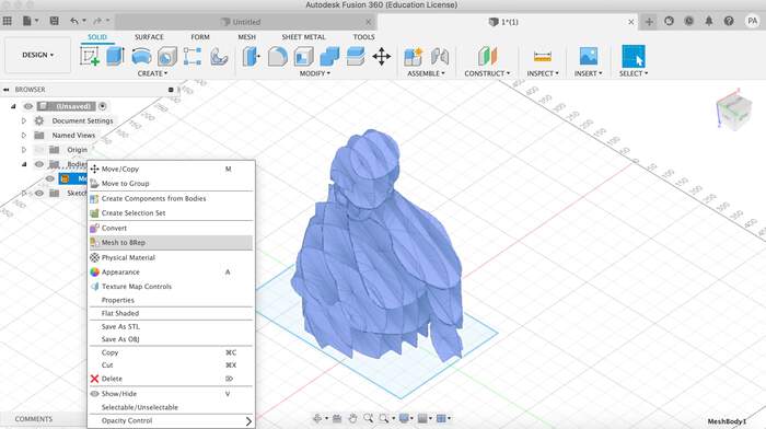
To cut off the legs I made a cube and then used the combine option. This did not work because the body was a mesh. So I had to convert the mesh by changing it to BRep format.

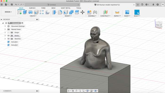
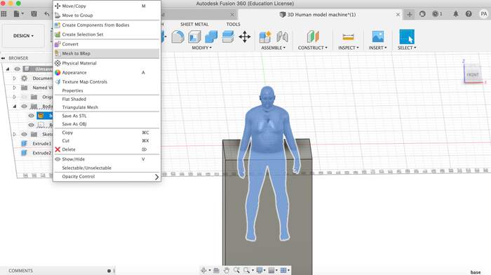
-
This made Fusion360 go very slow but it worked:
-
Lucia made a first tryout for the mechanism so I decided to make the first try of the anatomical look:
-
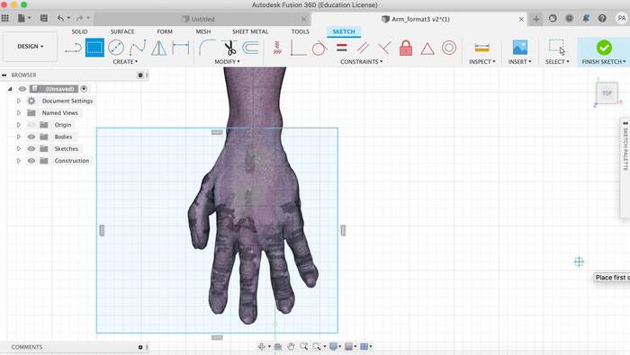
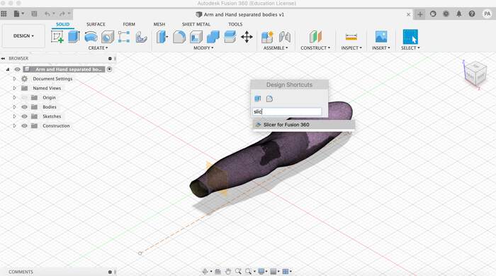
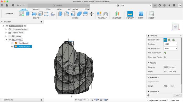
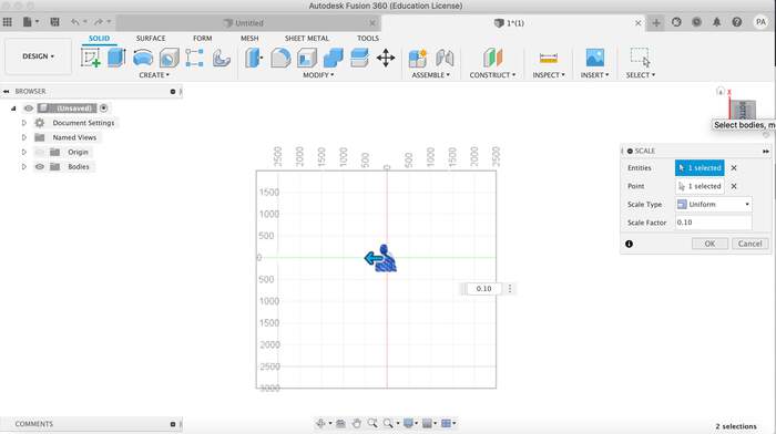
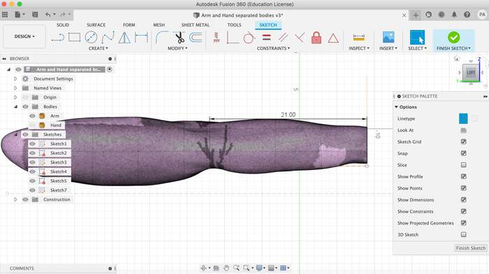
Phillip found an arm and hand model which looked fairly like what we wanted from CGTrader. I opened this in Fusion 360 and realised the arm was 700cm(too big!). I now have to scale it.
-
I open the STL file of the arm. With Philip we scaled so it would be 71 cm and drew and drew and offset plane between the arm and wrist. Now we went into mesh and did a cut (I separated arm and hand in two body parts):
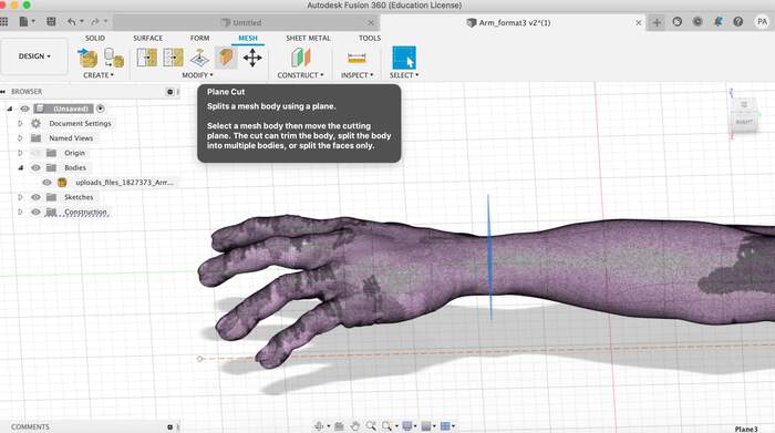
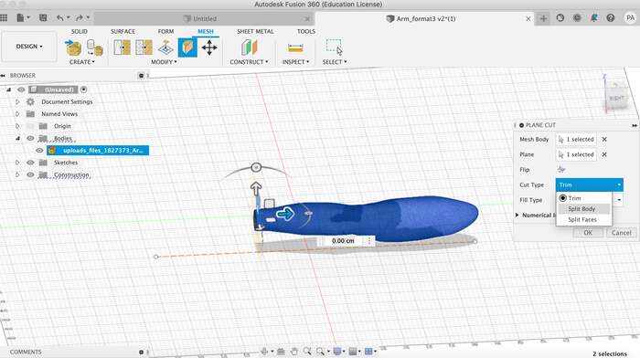
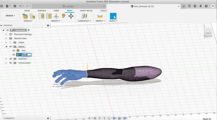
-
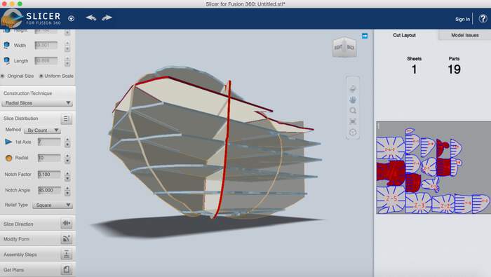
I hided the arm and looked for the Fusion360 Slicer plug-in
-
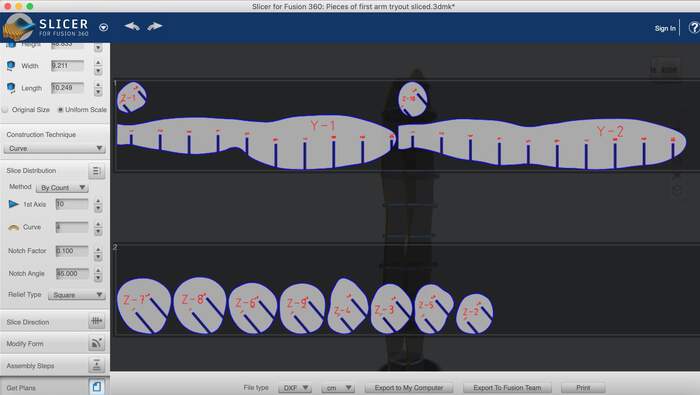
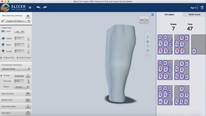
I opened the arm with the slicer tool by searching it in Fusion360 and then opening the arm in the Slicer tool. This plug-in has many different ways of slicing the arm. It is a very handy tool I will use more!
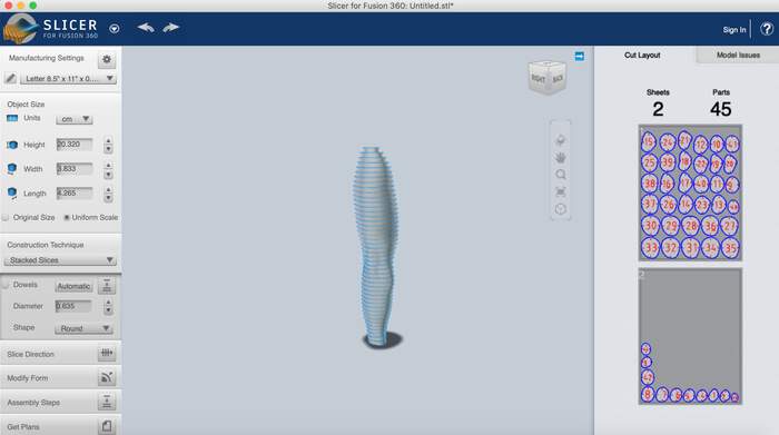
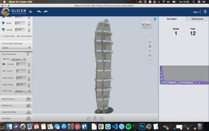
We will be testing two ways of slicing it:
- Stacked slices
-
Curved slices
-
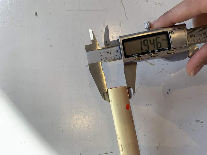
In both cases the PVC pipe will have to go through it so I measured the diameter and changed the diameter douwel:
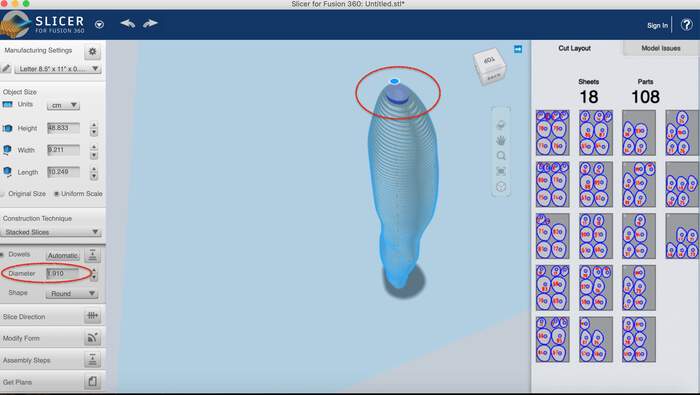
-
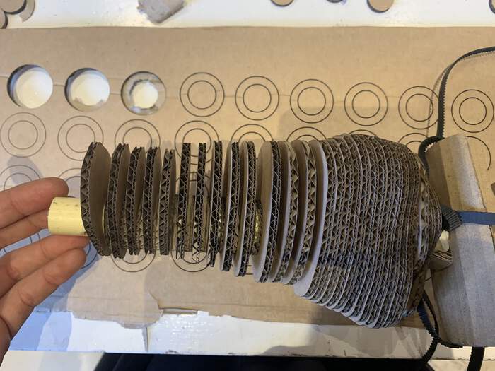
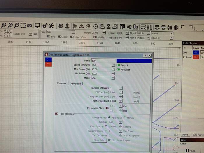
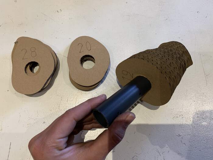
The cardboard thickness is 3.85mm, I changed the thickness un Fusion Slicer 360 to 0.77mm so it would give me less pieces (this was only to see the look of it so I tried to saved material for the first test). I saved is as DXF and sent it to the laser cutter.
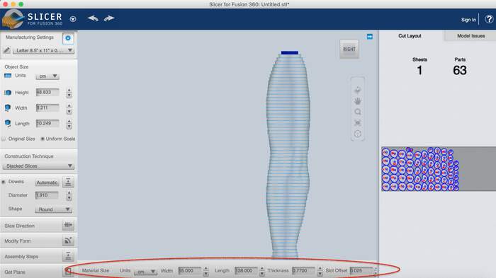
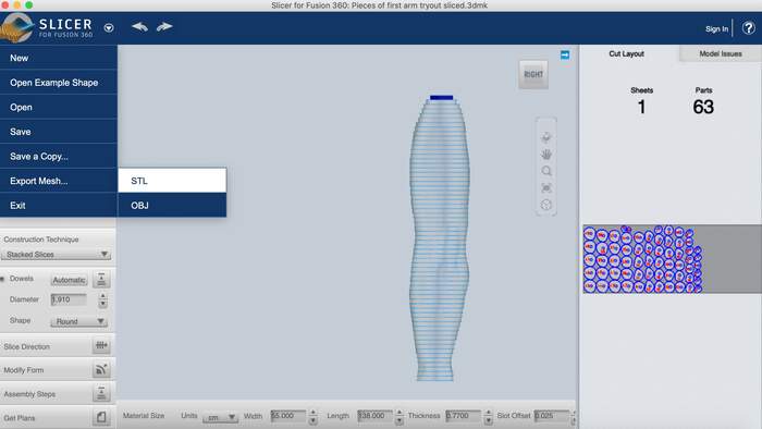
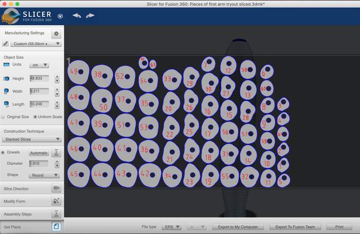
-
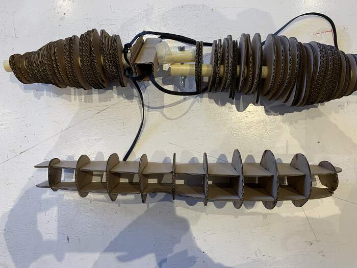
The look of the stacked slices:
Second tryout of anatomical arm:
-
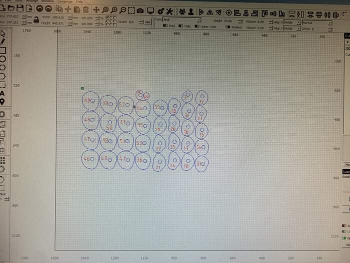
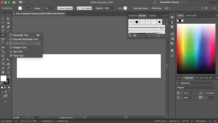
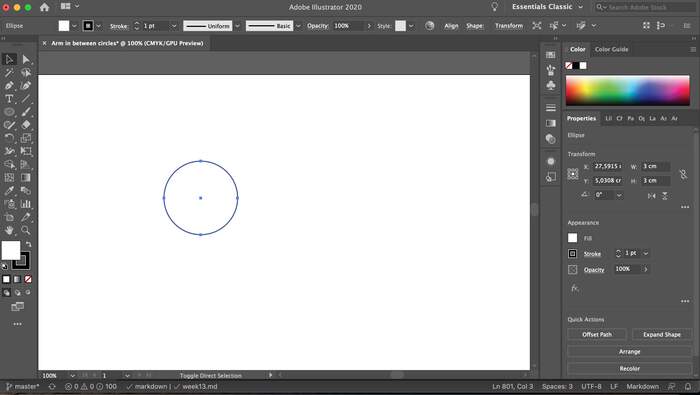
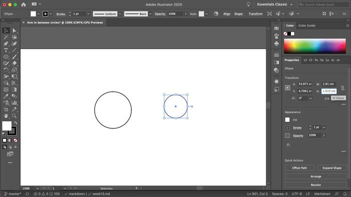
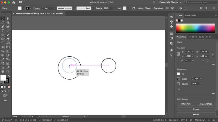
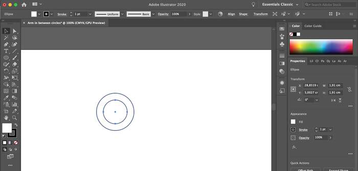
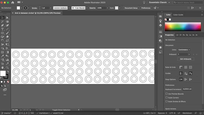
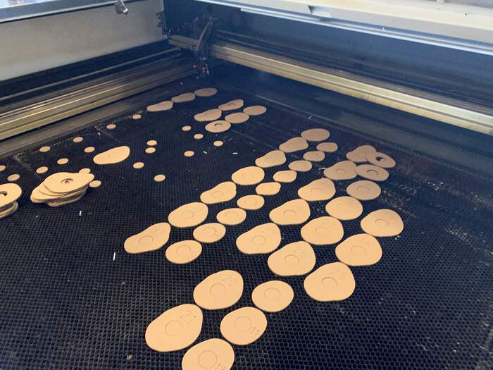
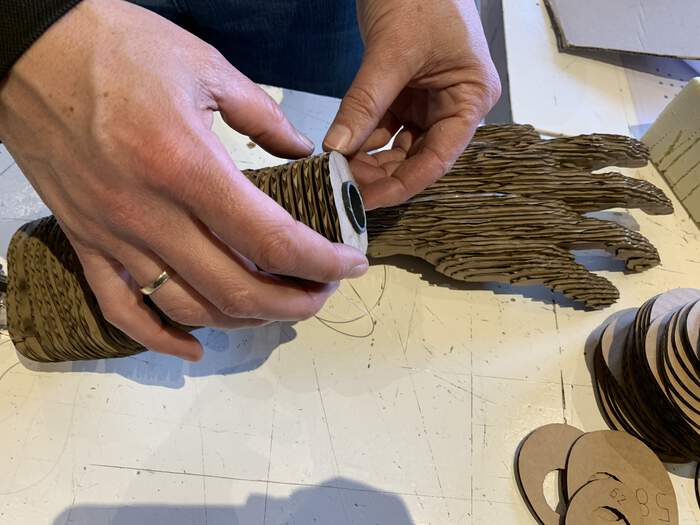
As Phillip was doing the hand with stacked slices format I decided to go for the stacked slices arm. I had doubled the cardboard thickness but the pieces did not stay in place so I decided to do circles in between the pieces to hold them in place with Illustrator. The other option would be to do the 120 pieces of the arm. I had to cut out with the laser cutter: 62 circles with a diameter of 3cm and a douwel circle inside of 1.910cm, leaving 0,5 cm on both sides.
-
Process of Illustrator:
-
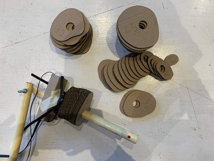
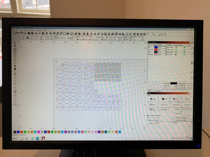
I cut this in the laser cut and it looked like this:
-
My final opinion was that I would do the stacked slices with circles in between because we were more happy with the end design overall.
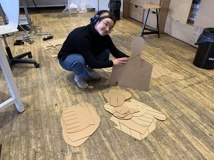
First tryout of torso anatomical look: cutting cardboard in the laser cutter
-
For the torso it is important to note that the torso needs some space to place an arm shoulder motor, probably it will need some areas to cable storage and it will also have to have some kind of shoulder opening to attach the arm hinges to it. For this, I have decided to first do a cardboard prototype to test all these aspects physically.
-
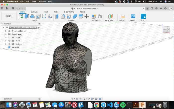
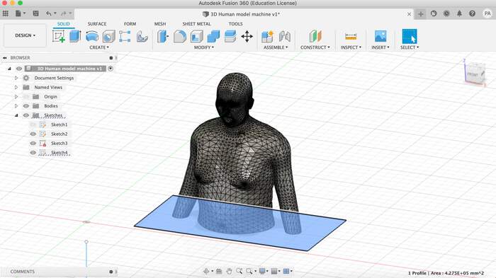
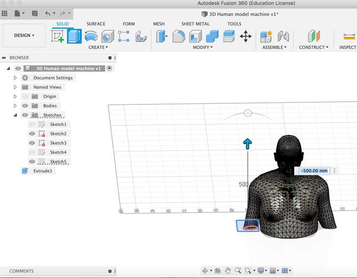
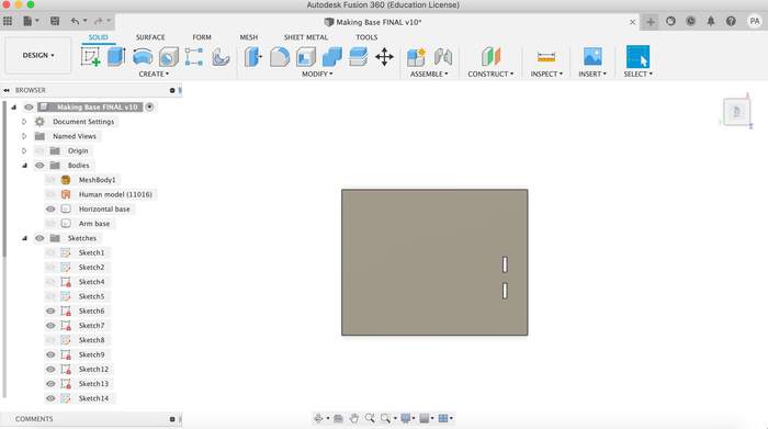
I had already modeled the Human body with Make Human in the previous step so I had my body in Fusion (with the legs cutout because we don’t need).
-
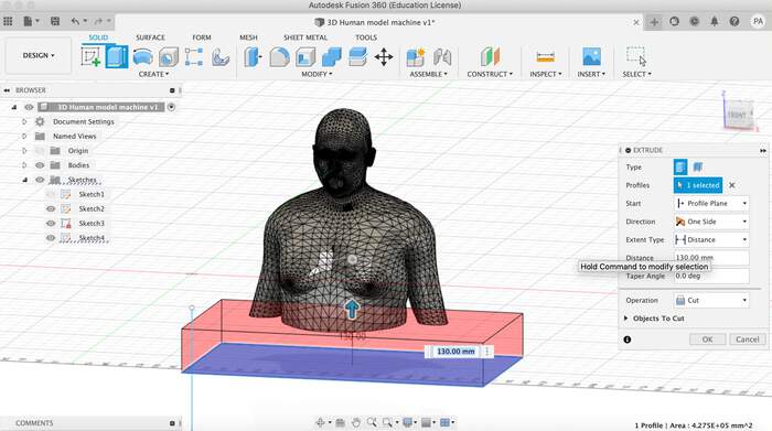
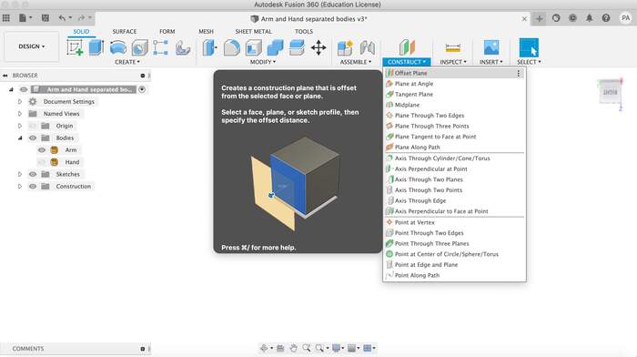
I will remove one of the arms to the model and separate the head for the cardboard tryout by creating a rectangle and extruding with the cut type.
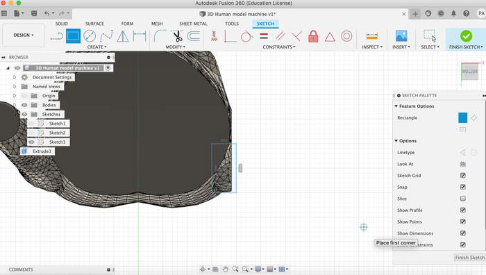
-
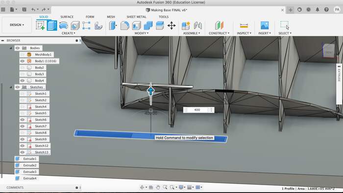
The radial sliced option in Fusion 360 Slicer seems like the best option as it as these spaces to store cables and also somewhere where to attach the arm.
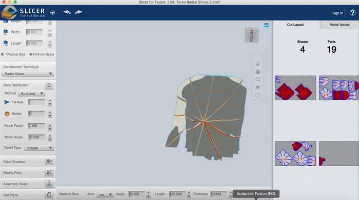
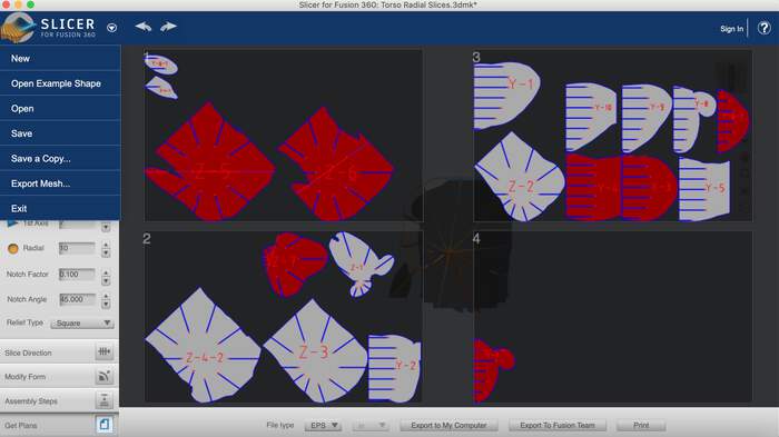
-
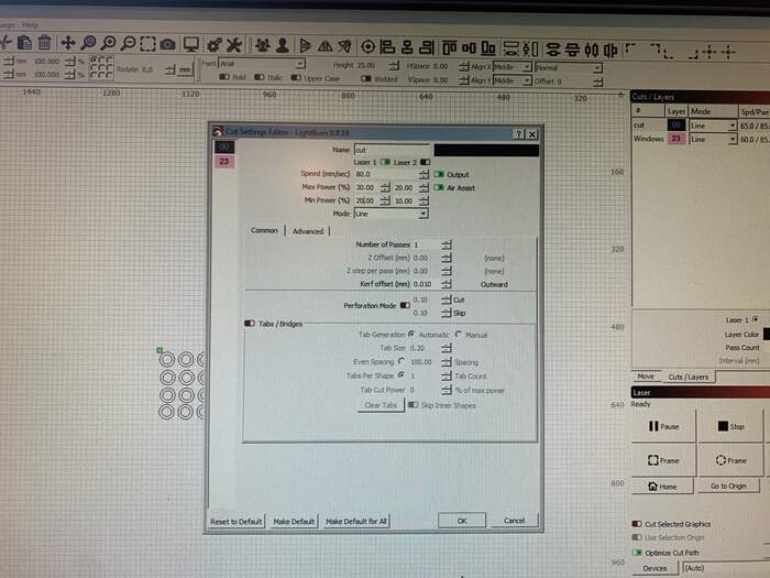
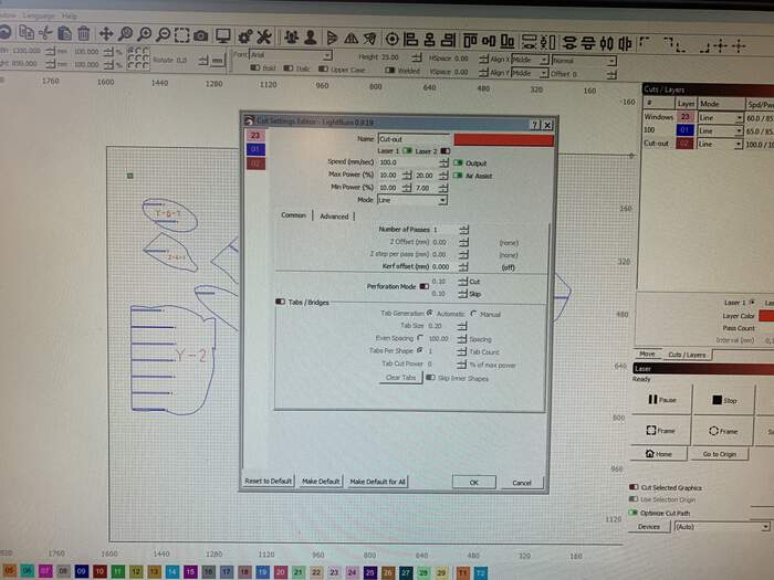
I rotated the spaces so they would somehow leave a space for the cables and possible storage of the motor. I measured the cardboard pieces thickness which was 3.80mm. From the laser cutting week I picked the kerf values as it was the same thickness and did the same calculations to be able to press fit the pieces.
3.80mm - 0.152mm -0.2 = 3.448mm
-
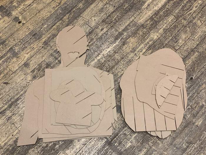
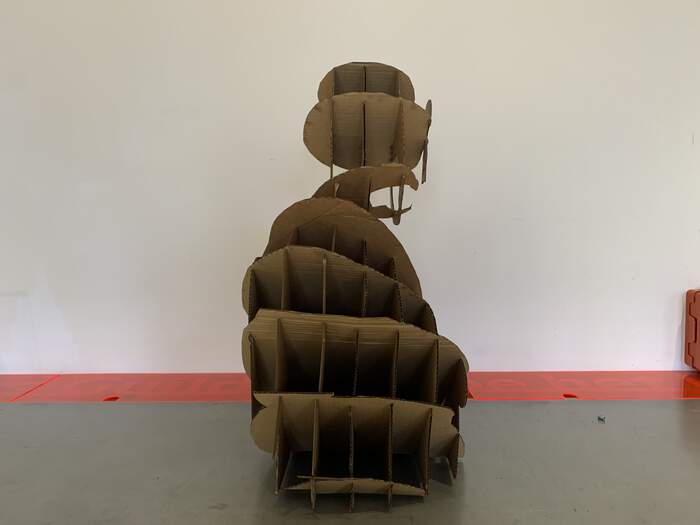
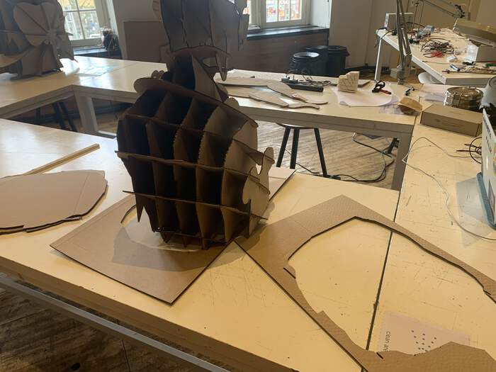
After cutting the pieces in the laser cut and assembling the pieces we could have a closer look at how to assemble the arm and the torso together:
-
I then realised I had taken off the wrong side of the arm:
-
Reflections: I had to go back in Fusion and extrude the other arm instead. I also realised the torso was too high so I extruded the bottom part of the model (leaving it 35cm-40cm tall without the head). After realising how hard it was to press fit the different slices I thought that making the torso with wood was a very difficult option and it would be better to leave it with cardboard and make a wooden sturdy base instead. This base would have a bottom base and a vertical piece of wood attached to the base to attach the arm to it. This would also be cut with CNC.
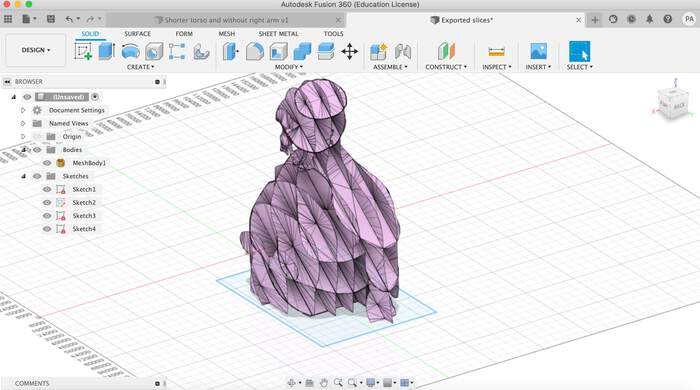
Second tryout of torso anatomical look: slicing the opposite arm and making it smaller.
-
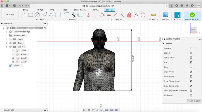
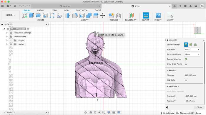
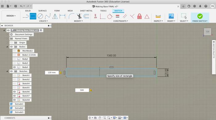
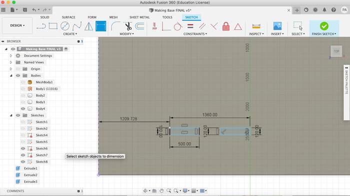
I reopened the model in Fusion360. I removed the opposite arm and reduced the height of the torso as the table we will be placing is quite high. I measured that the torso - neck had to roughly be 35-40 cm tall, so I made it 37cm.
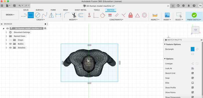
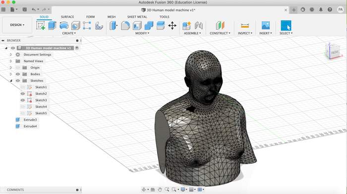
-
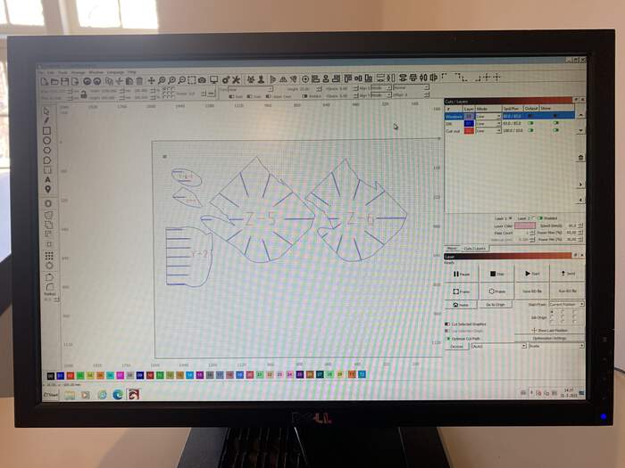
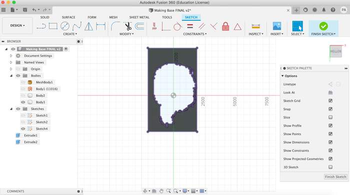
This time I decided to slice the head and the body at the same time so the model would be more stable. I also left the mouth open just in case in the future we would like to do something with it.
-
I calculated the average thickness: 2.62mm - 0.152mm - 0.2 = 2.27 mm and cut the pieces in the laser cutter:
-
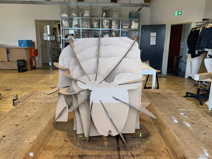
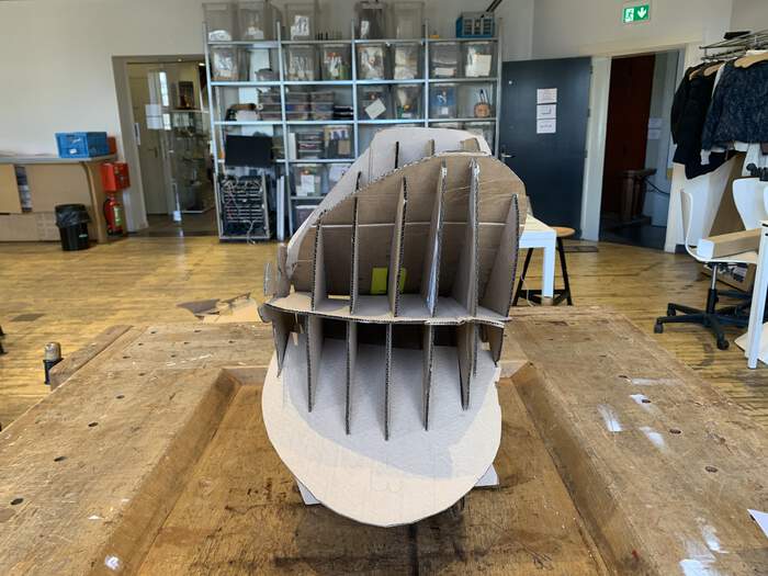
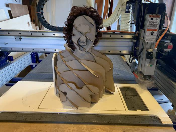
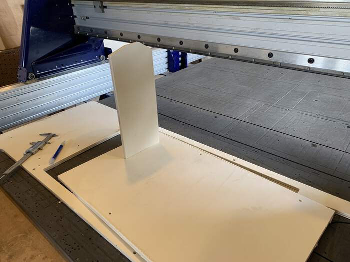
After assembling all the pieces it looked like this:
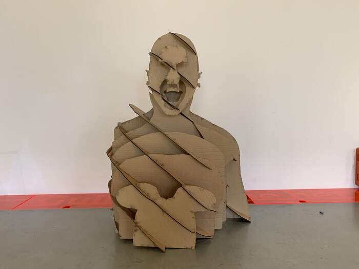
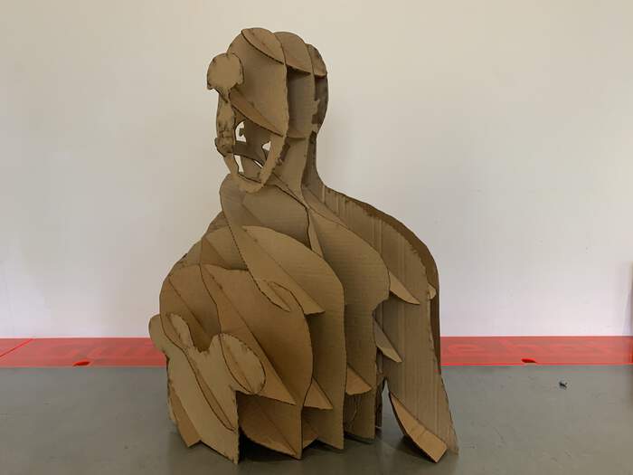
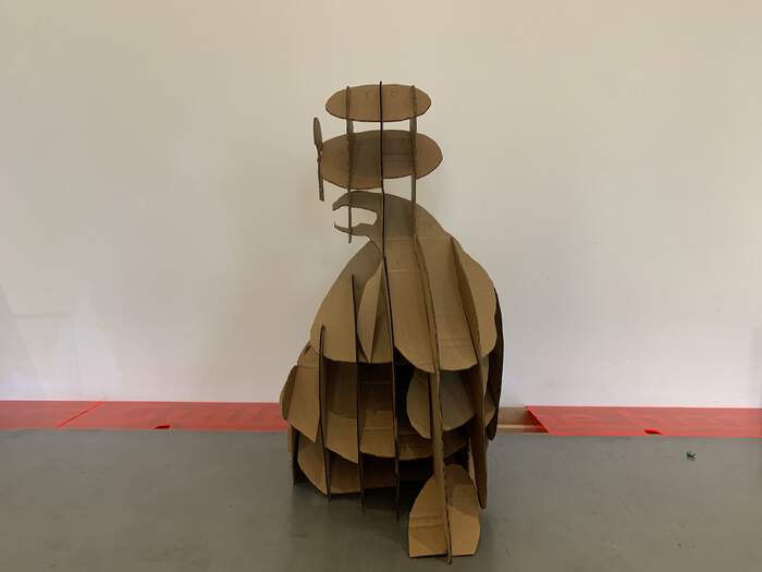
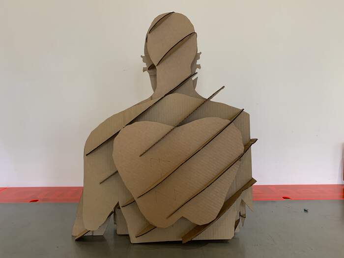
-
Torso and head are done!
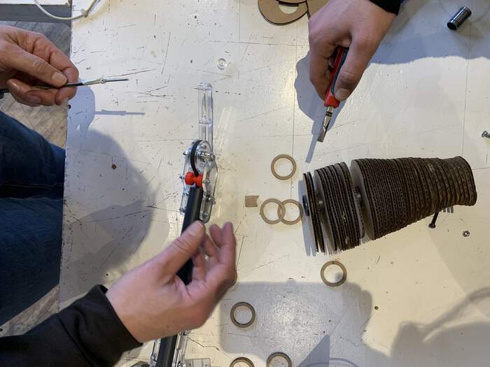
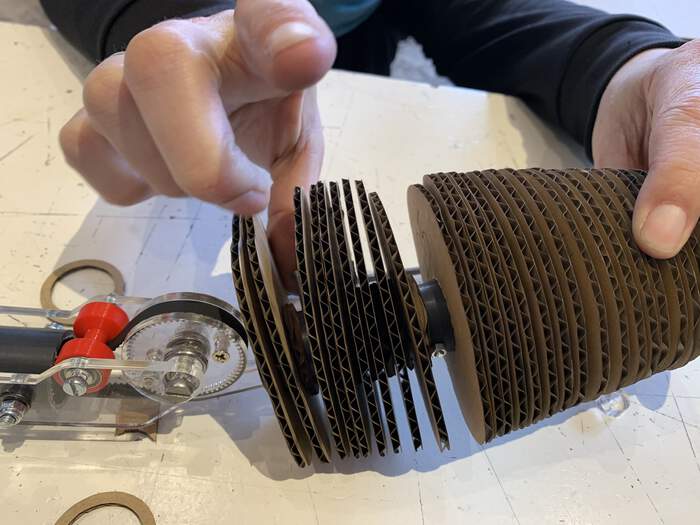
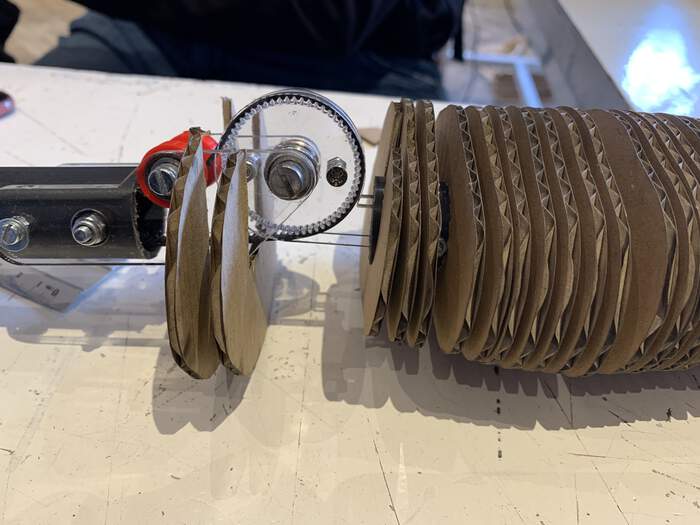
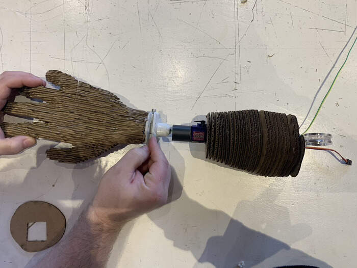
Second tryout for the arm:
-
As Lucia changed the pipe for mechanism I had to recut the whole arm again in the laser cutter with new douwel holes (the pipe had a 25mm diameter). So I opened the previous file I had for the arm in Fusion Slicer 360 and changed the diameter of the douwel to 25 mm and also the thickness of the cardboard.
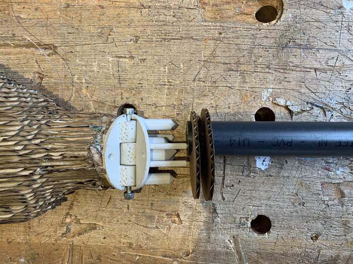
-
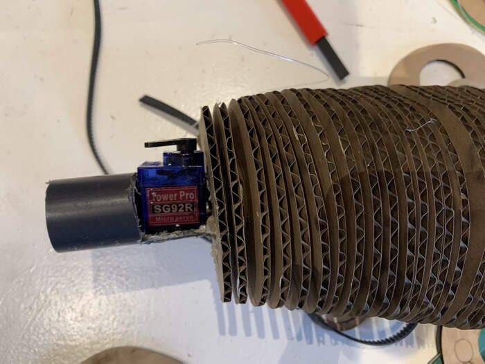
The pieces of the arm fit but I have to wait till the whole mechanism(belt) and cables for the motor are assembled inside the pipe until I place them on.
First tryout for the base of the torso
-
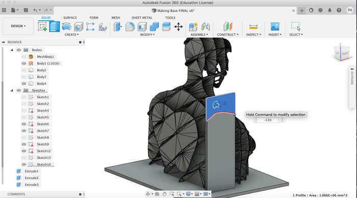
As I finally decided to make the torso and head of cardboard I had to create the base to attach the motor to it. My initial plan was to loosely “press-fit” the base of the torso to the wooden base by combining the base and the torso in Fusion360 and creating the holes for it.
-
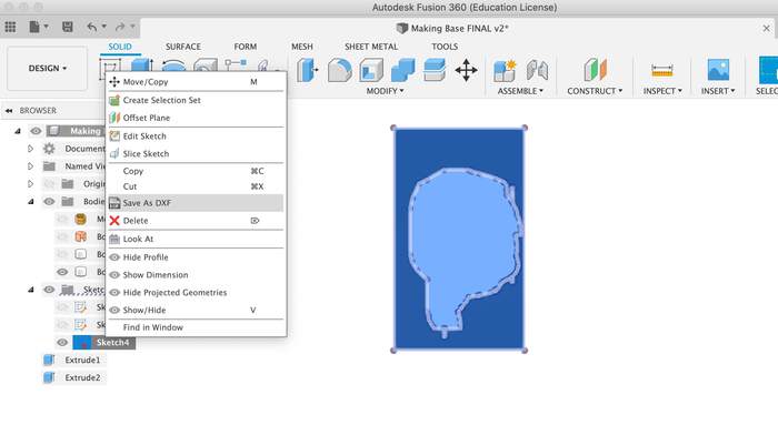
What I did was open the stl file model of the torso and head sliced in Fusion360.
-
I started by creating the wooden base under the model:
-
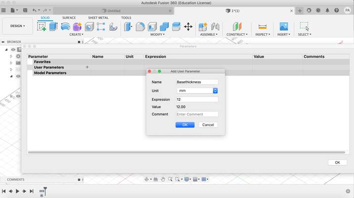
I wanted to create a parameter for the thickness of the wooden base but Fusion360 did not gave me the option.
-
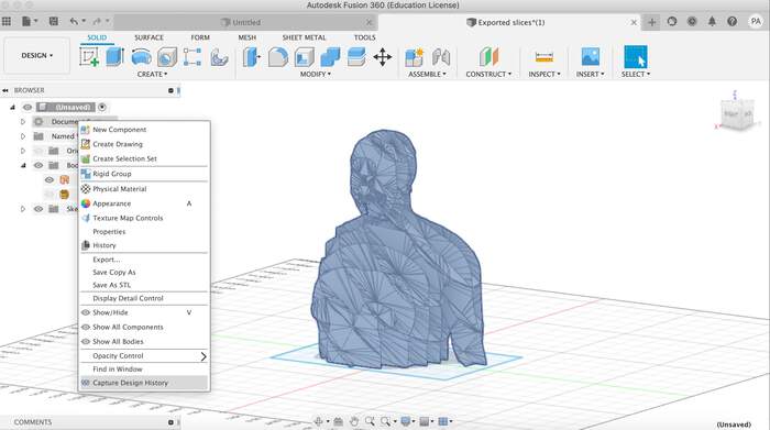
I realised that it was because I was working with mesh so I changed the mesh to BRep so I could actually work with it with other bodies.
-
I still did not have the parameter option so I operated the design history and wala! I had parameter (not really sure why this is connected like this)
-
I created a parameter for the wood base and drew the base:
-
When I did this I realised the body was too big so I had to scale it down:
-
Then I tried combining both pieces: the model and the base but it would not work so I created points around the base of the model, connect them and cut through the base:
-
I laser cutted this on cardboard to see how it worked but it was too big:
Second tryout for the base of the torso
-
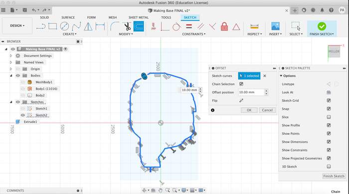
I tried drawing around it more precisely and then offsetting it but after cutting it I realised it had a similar output.
-
So I decided to make a straight base and just press fit the arm piece to it.
Third tryout for the base of the torso
-
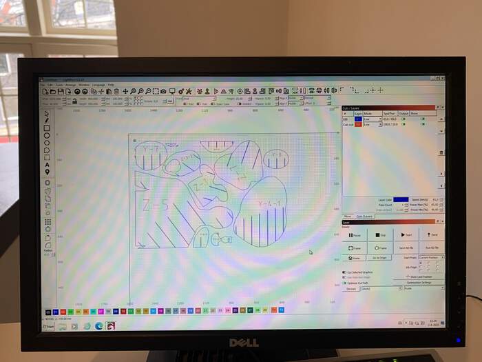
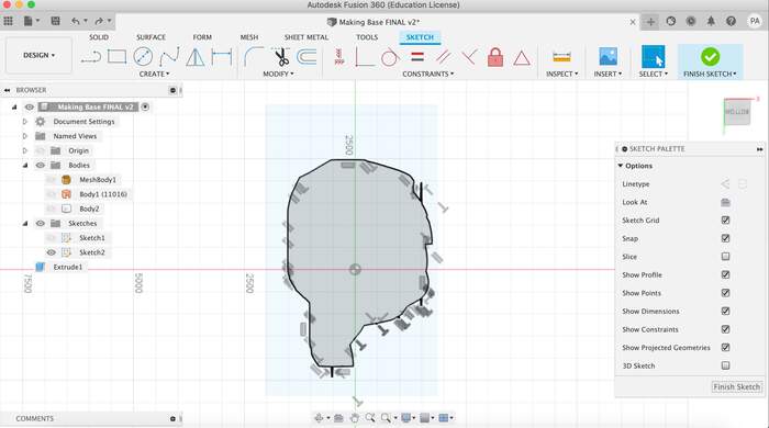
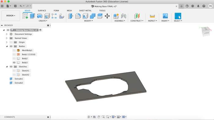
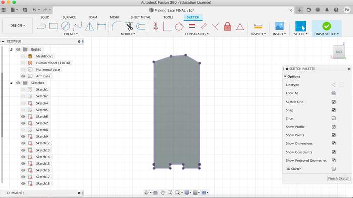
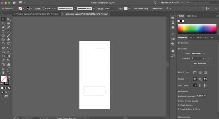
I drew both structures:
-
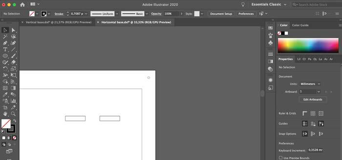
Projected them and exported them to Illustrator:
-
I then added the drew holes, and modified the units and artboard:
-
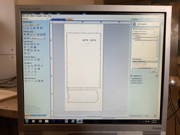
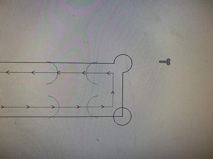
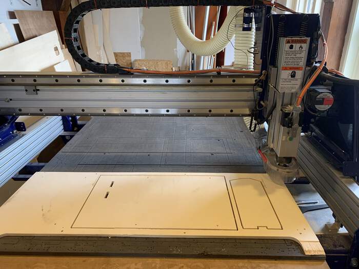
I sent this to V-carve and followed all the steps from the CNC week assignment. Made all the toolpaths and sent it to the CNC.
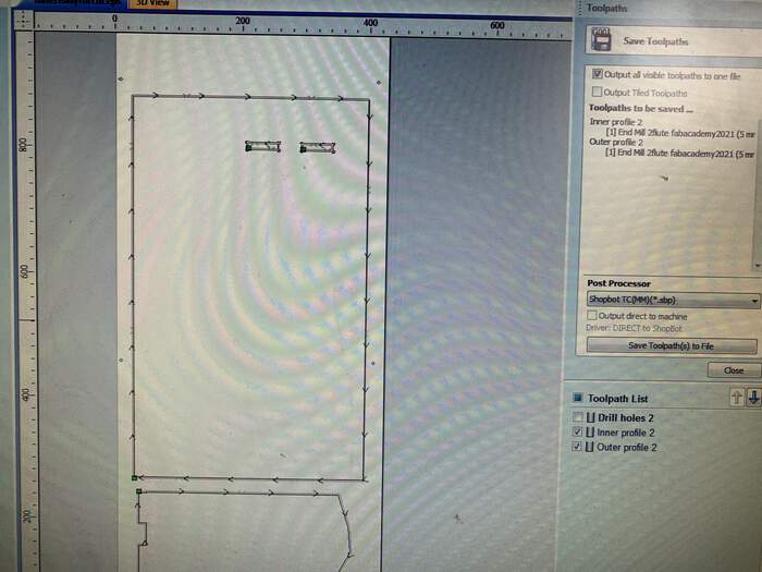
-
The third try did not cut through the wood and I had a problem with the x and y axis (I did not get the coordinates correctly) so I had to unscrew and screw again a second wooden board.
Fourth tryout for the base of the torso
-
I screw another board.
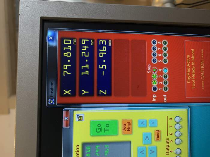
-
Made sure I had the x and y coordinates in case anything went wrong:
-
I also added dogbones directly in v-carve:
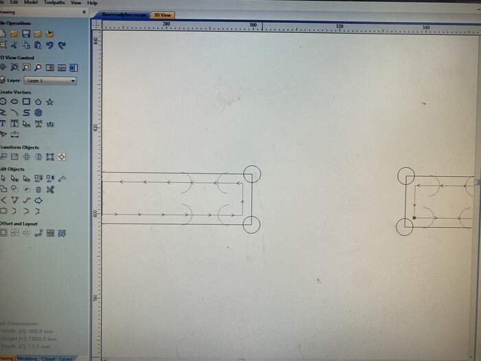
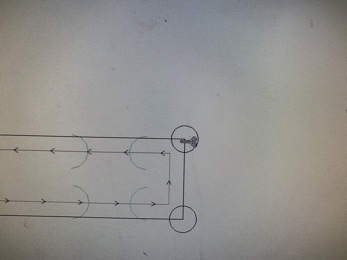
-
I also added 0.60 mm to the cut depth. This time it all went good:
-
Until I realised the press-fit did not work by 1mm:
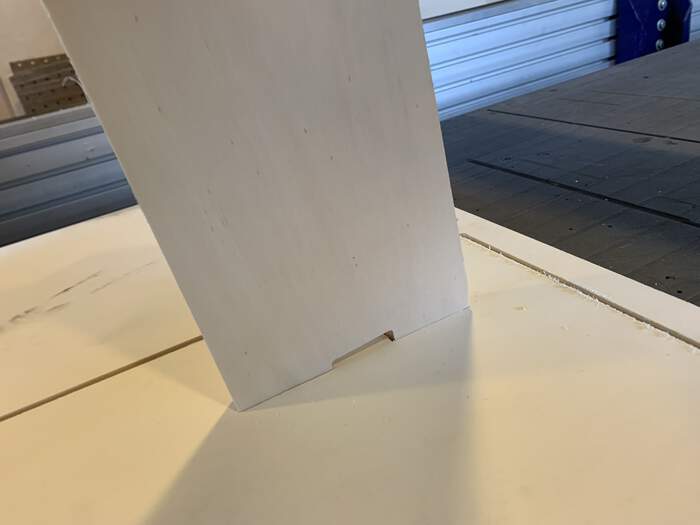
-
So I sanded the border and it worked:
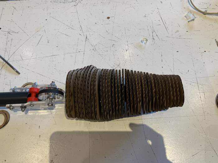
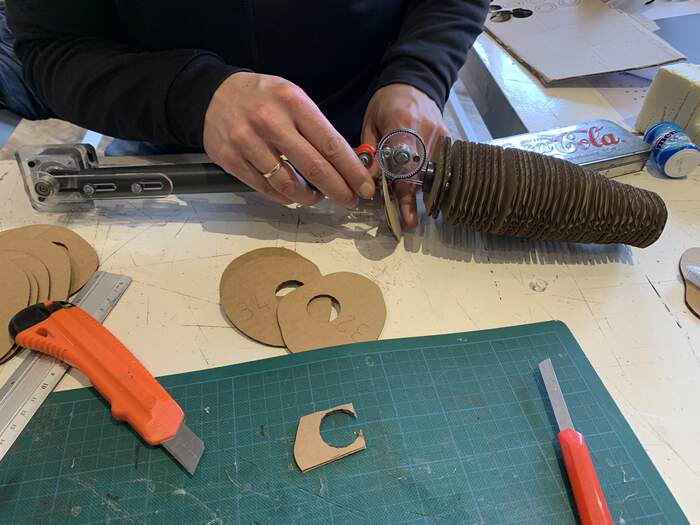
Third tryout for the arm:
-
We realised that the forearm was not aligned with the wrist hinge:
-
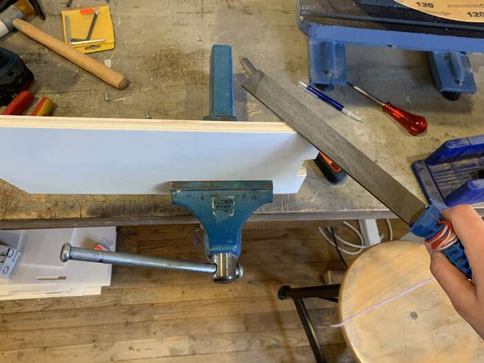
To solve this I re-printed the forearm and changed the douwel slightly more in the center, for this I had to cut the forearm as I had done with wrist and arm:

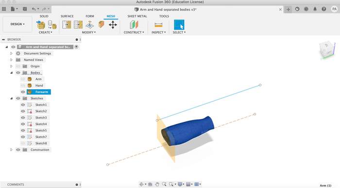
-
This now worked perfectly and did not affect the overall design:
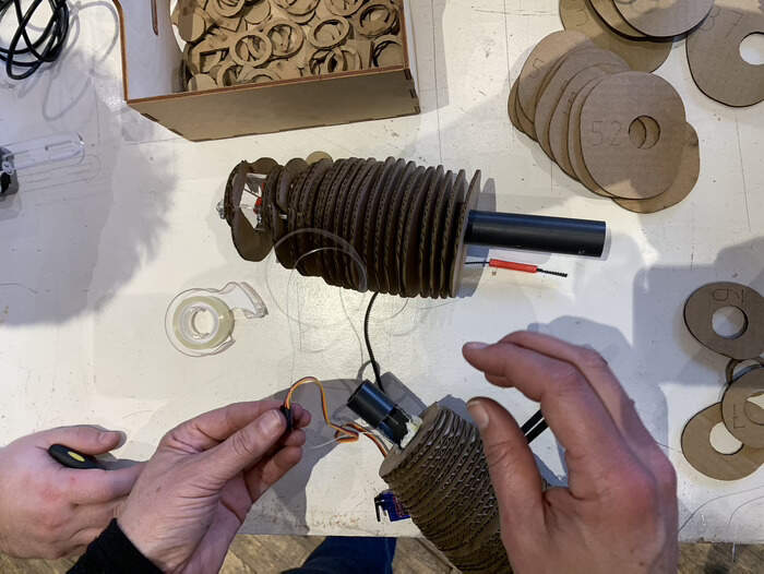
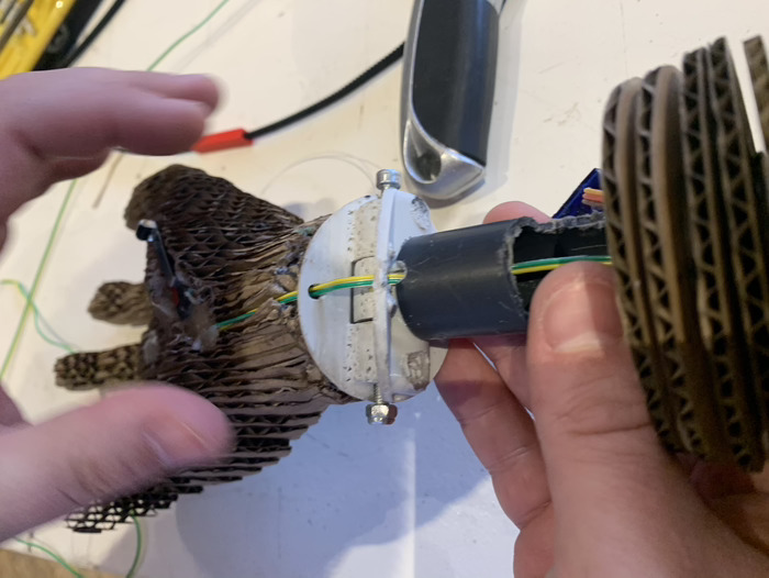
Final adjustments:
-
The final adjustments were all about working out the different parts and assignments together, for this I did extra cuttings in the laser cutter, stuck parts with super glue, did openings for the different motors and cables:
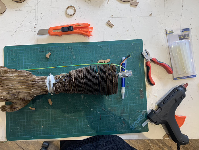
-
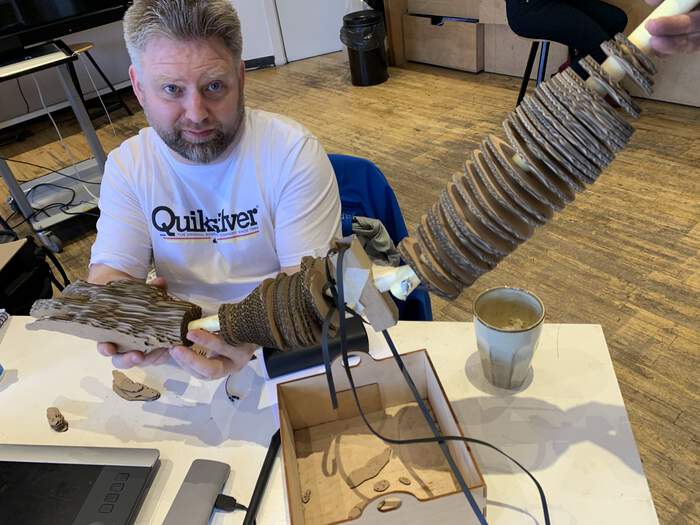
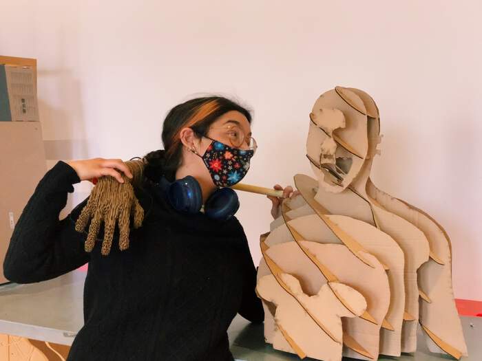
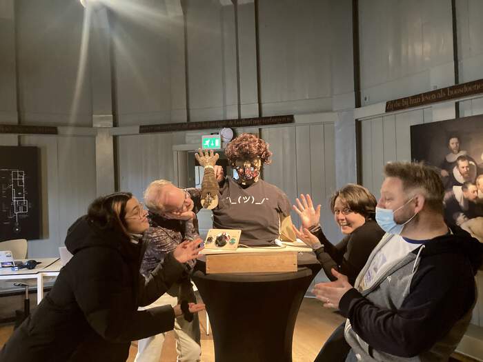
This is our final result:
-
You can learn more about the different tasks my other colleagues did: Lucia’s arm mechanism, Phil’s hand and video editing and Erwin’s electronics and motors.
-
For the final presentation we also had to do a video, Phil did all the video planning, filming and editing. You can see what our machine is, what does it do and we made it here. You can also download the design files from there too!
These two weeks were quite a lot of work. I really worked and understood better how to make press fit pieces, work with laser cutters and I loved the slicing tool I discovered which can become really useful for the future. I would have improved our overall communication as a group to know which things I could have incorporated better to my design part (leaving corresponding spaces and adjusting parts together better).