Week 03: Computer-controlled cutting
Assignments:
-
Group assignment: characterize (describe/understand the nature and features (of your particular laser cutter)) your lasercutter’s focus, power, speed, rate, kerf, and joint clearance, document your work (individually or in group)
-
Individual assignment: design, lasercut, and document a parametric press-fit construction kit, which can be assembled in multiple ways. Account for the lasercutter kerf. Cut something on the vinylcutter.
What to learn:
-
Demonstrate and describe parametric 2D modelling processes
-
Identify and explain processes involved in using the laser cutter.
-
Develop, evaluate and construct the parametric construction kit
-
Identify and explain processes involved in using the vinyl cutter.
Have you?
-
linked to the group assignment page
-
Explained how you parametrically designed your files
-
Documented how you made your press-fit kit
-
Documented how you made your vinyl cutting
-
Included your original design files
-
Included your hero shots
DOUBT: What is valid for a construction kit Answer: something more than a finger joint box that you can assemble multiple ways.
DOUBT: Is it compulsory to design my own file in Vinyl cutting? Answer: No, but you must acknowledge where you found it.
Steps of this week assignment:
Step 1: Group assignment
Characterize (describe/understand the nature and features (of your particular laser cutter)
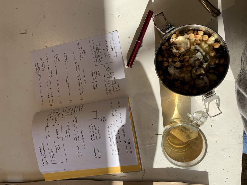
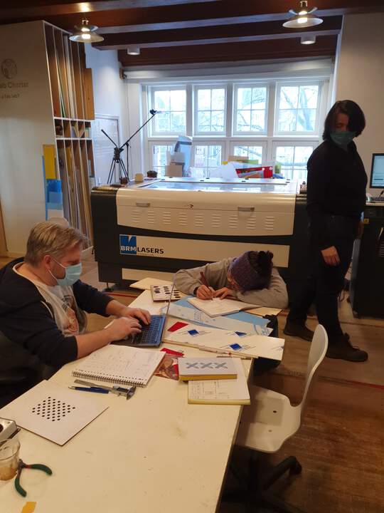
On Thursday we met at the Fab Lab, after two weeks of online working due to corona rules. Our instructor, Henk, showed us around the Laser-cutter. This is a small sketch I did around the main features of the machine we have at den Waag (BRM LASER)
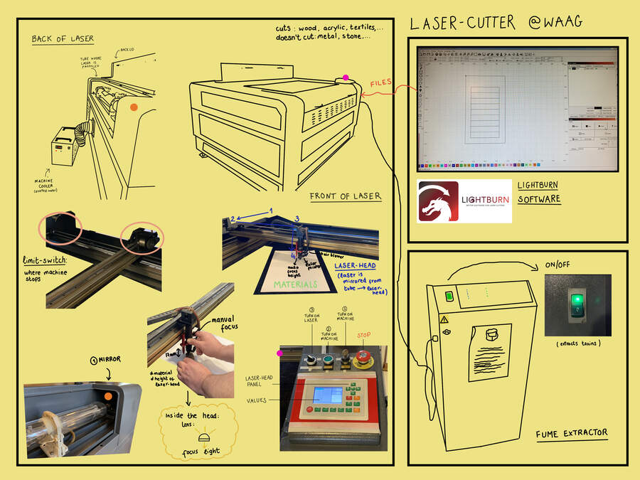
Additional info:
-
It is a CO2 laser
-
It is a 100 watt laser
-
It has an x axis and y axis (the z axis we only use it to focus the laser-head on the material)
-
In the laser language: lines stand for cutting and filling stands for engraving.
-
Keep the lid closed at all times, unless loading material with the laser button number 3 turned off.
Understanding speed and power
-
Different material, different variables of speed and power so you get a perfect cut
-
If you reduce speed there is more energy concentrated in 1 point so it cuts more through the material
-
The power from the lines = travelling power(max.power) differs from the power of the corners(max.powers) so you also have to play around within these values.
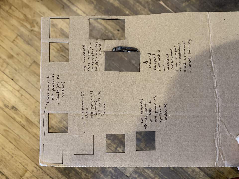
Our instructor, Henk, showed us briefly how the material cut is different if you modify speed and power:
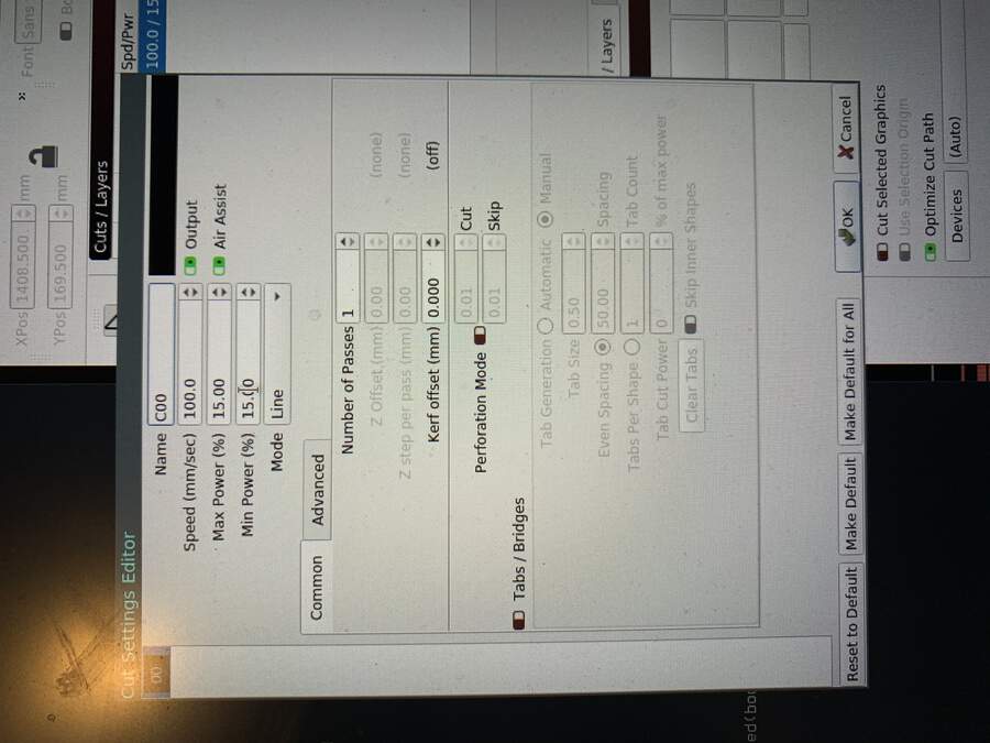
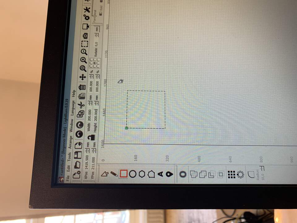
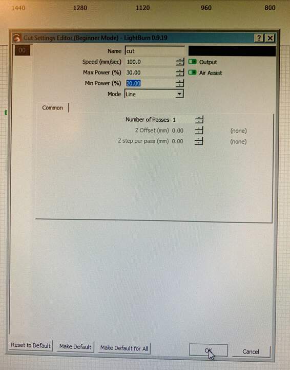
To change this you adjust the values in editor settings in Lightburn (see below):
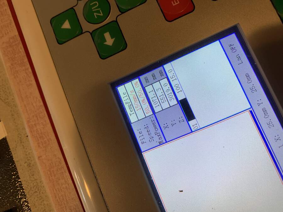
This is also shown in the value panel in the laser-cutter machine:
Understanding Lightburn settings while having lunch :)
As a group, with Lucia and Philip we did a simple shape test to test the power and speed and discover which were the best machine settings for different materials.
We started drawing a square in Lightburn which we will would then cut out in different materials:
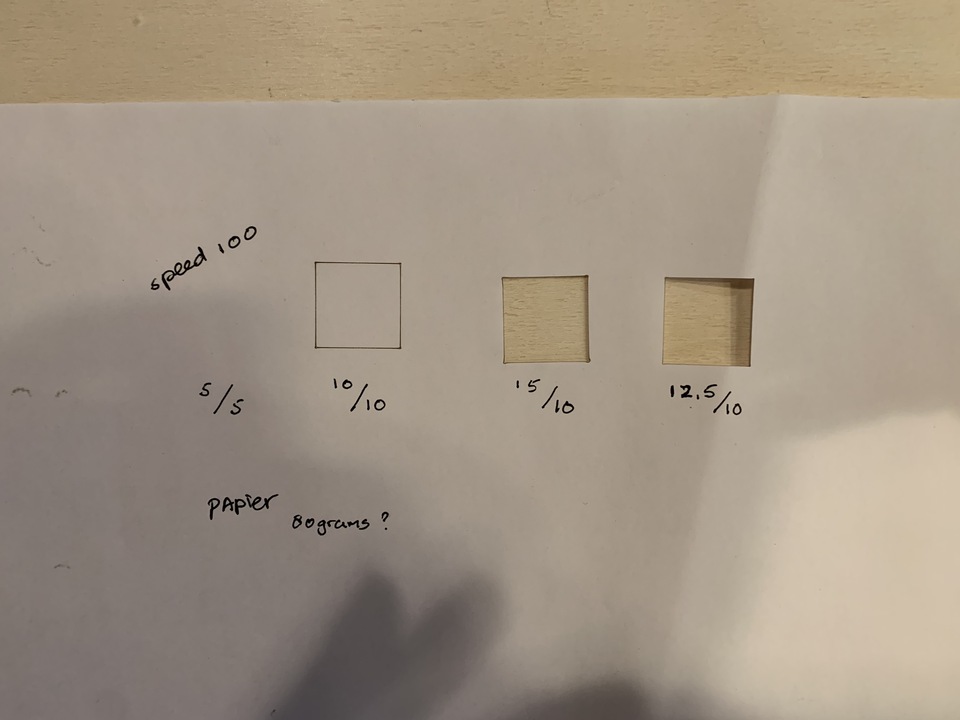
Test 1 speed and power: Paper
-
We place paper in laser-cutter and adjust manual focus with laser-head
-
Open Lightburn in computer
-
Make square 2cm x 2cm
-
On machine panel press power button 1, press power button 2
-
Place laser head at origin
-
Press frame button to double check the laser will draw the shape within the material placed
-
Turn on Air Extractor
-
Adjust speed + power parameters:
| Speed | Max. Power | Min. Power |
|---|---|---|
| 100 | 5 | 5 |
| Did not work. So we change the settings again. Like this till we find the perfect machine settings to cut paper. |
| Speed | Max. Power | Min. Power |
|---|---|---|
| 100 | 10 | 10 |
| Cuts but it does not cut through. |
| Speed | Max. Power | Min. Power |
|---|---|---|
| 100 | 15 | 15 |
| Cuts through but a bit burnt so we lower the min.power. |
| Speed | Max. Power | Min. Power |
|---|---|---|
| 100 | 12.5 | 10 |
| Optimum cut. |
Test 2 speed and power: Corrugated cardboard (1)
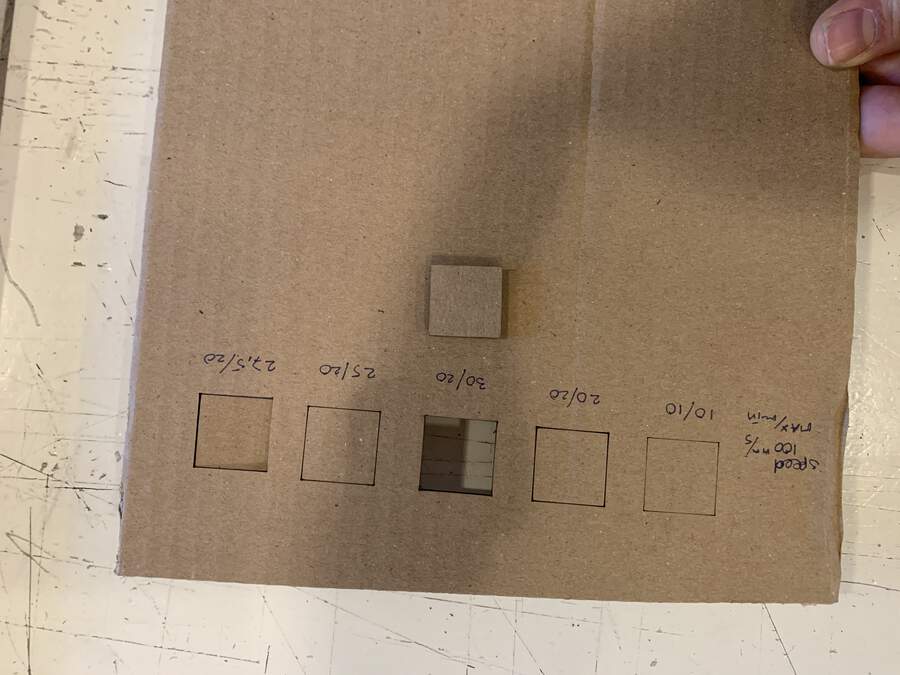
Material thickness: 2,75 mm
| Speed | Max. Power | Min. Power |
|---|---|---|
| 100 | 10 | 10 |
| Cuts slightly top part |
| Speed | Max. Power | Min. Power |
|---|---|---|
| 100 | 20 | 20 |
| Cuts lines on top and corner to the back. |
| Speed | Max. Power | Min. Power |
|---|---|---|
| 100 | 30 | 20 |
| Optimum cut. |
Test 3 speed and power: High density cardboard (2)
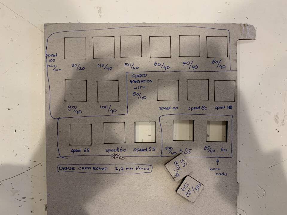
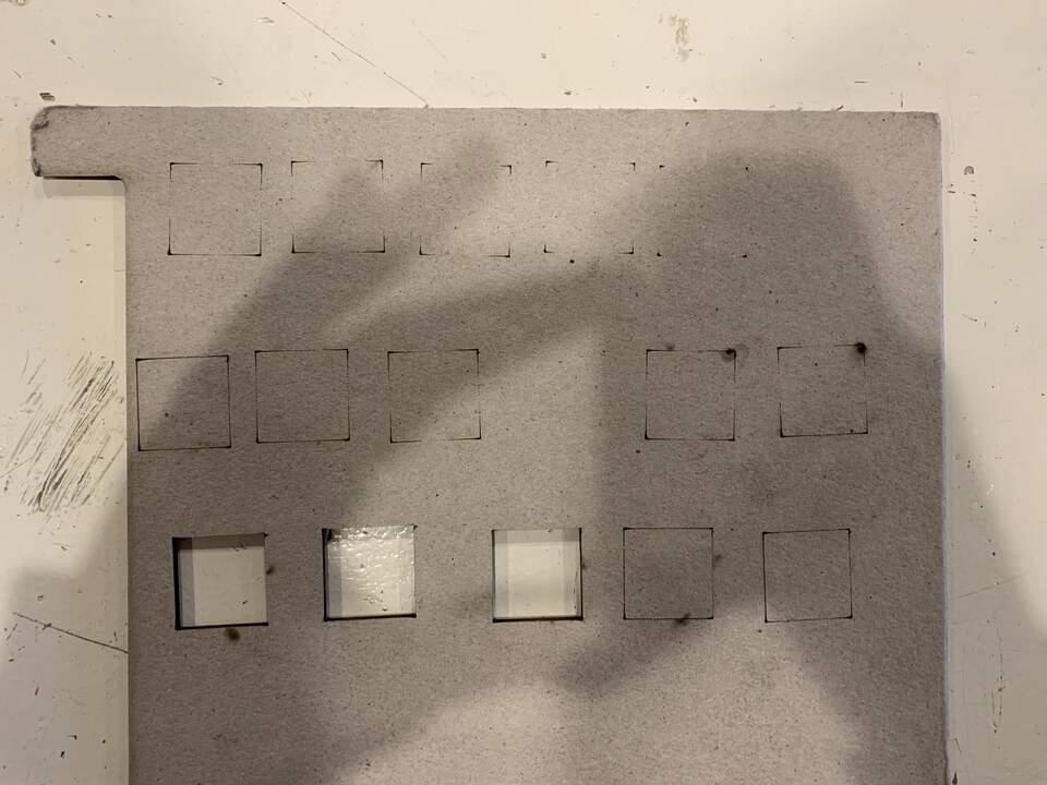
Material thickness: 2,90 mm
| Speed | Max. Power | Min. Power |
|---|---|---|
| 100 | 30 | 20 |
| No cutting through |
| Speed | Max. Power | Min. Power |
|---|---|---|
| 100 | 40 | 40 |
| 100 | 50 | 40 |
| Corners getting through |
| Speed | Max. Power | Min. Power |
|---|---|---|
| 100 | 60 | 40 |
| 100 | 70 | 40 |
| 100 | 80 | 40 |
| 100 | 90 | 40 |
| Corners bigger, lines not enough |
| Speed | Max. Power | Min. Power |
|---|---|---|
| 100 | 90 | 40 |
| One corner a bit burnt |
| Speed | Max. Power | Min. Power |
|---|---|---|
| 100 | 100 | 40 |
| Did not cut yet, so we will have to slow down the speed from 80/40 because this one did not have the burning effect |
| Speed | Max. Power | Min. Power |
|---|---|---|
| 90 | 80 | 40 |
| Nearly there |
| Speed | Max. Power | Min. Power |
|---|---|---|
| 80 | 80 | 40 |
| Lines at the back more defined |
| Speed | Max. Power | Min. Power |
|---|---|---|
| 70 | 80 | 40 |
| 65 | 80 | 40 |
| 60 | 80 | 40 |
| 55 | 80 | 40 |
| Pieces stuck but already had cut through |
| Speed | Max. Power | Min. Power |
|---|---|---|
| 60 | 85 | 40 |
| We change the max.power to 85, cuts through but has burnmarks, depends on your choice |
or:
| Speed | Max. Power | Min. Power |
|---|---|---|
| 65 | 85 | 40 |
| Some hanging fibres which you can cut out with a knife, and moves if we push. Optimal for me |
Test 4 speed and power: Wood 1
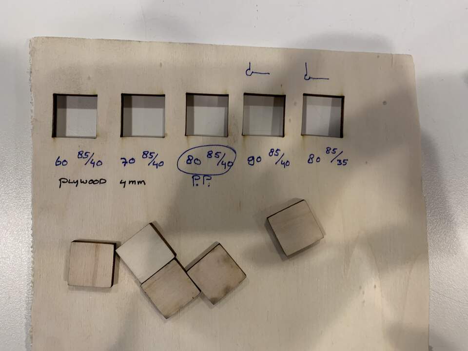
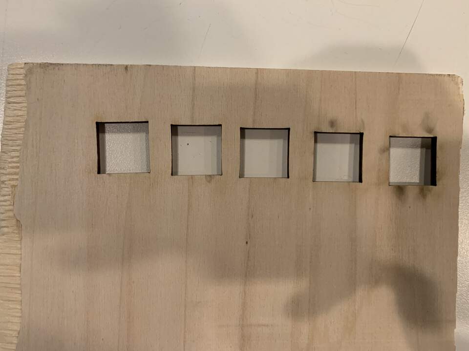
In order to hold your material flat when cutting we placed some weigh on top of it so it would flatten, as shown below:
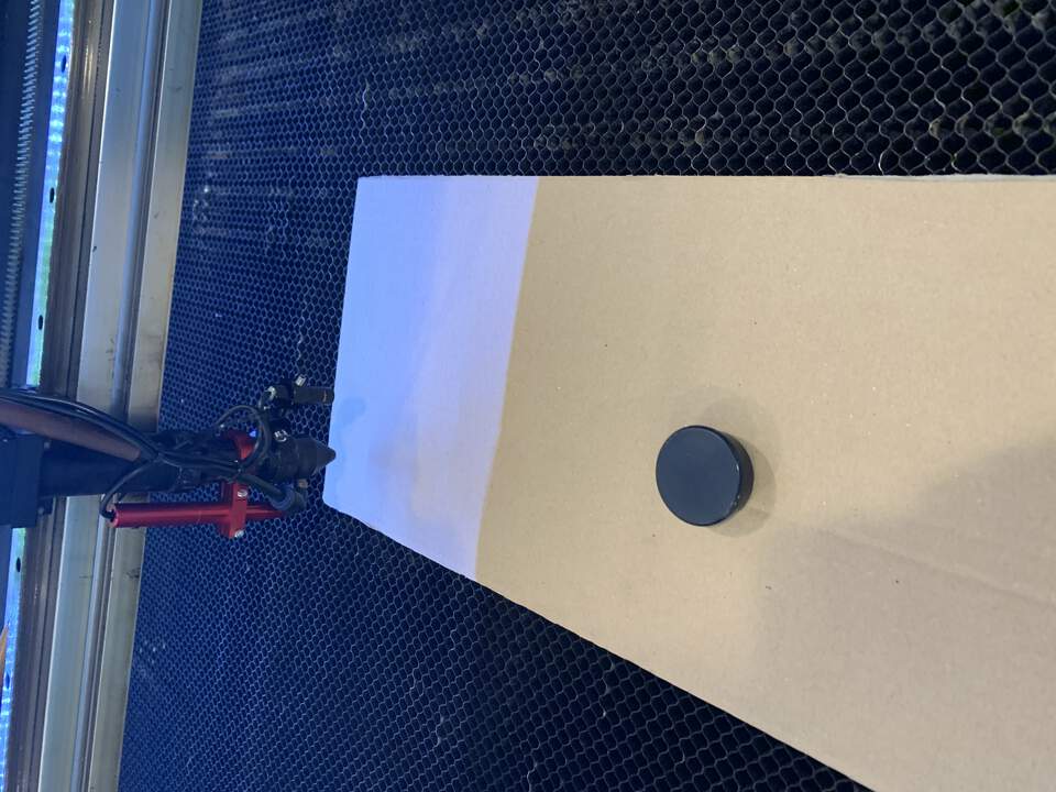
Material thickness: 3,91 mm but wood has more air in between.
| Speed | Max. Power | Min. Power |
|---|---|---|
| 60 | 85 | 40 |
| 70 | 85 | 40 |
| Cuts through well with some burnt marks at the back |
| Speed | Max. Power | Min. Power |
|---|---|---|
| 80 | 85 | 40 |
| Pretty perfect |
| Speed | Max. Power | Min. Power |
|---|---|---|
| 80 | 85 | 35 |
| Perfect, with better corners |
Test 5 speed and power: Wood 2
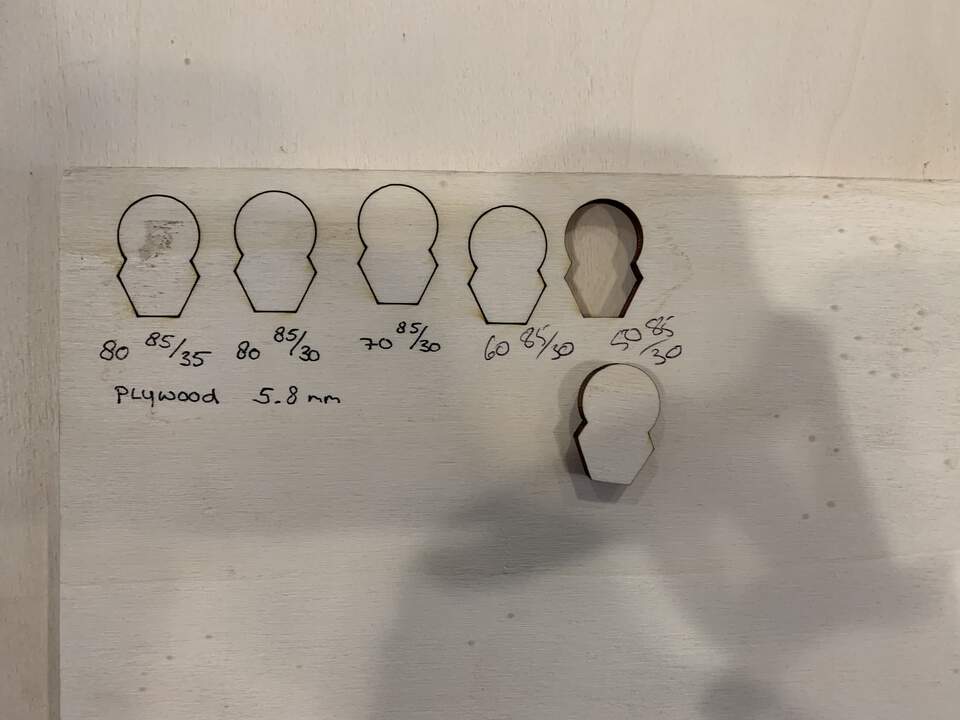
Material thickness: 5,81 mm but with much more air in between.
| Speed | Max. Power | Min. Power |
|---|---|---|
| 80 | 85 | 35 |
| Cutting corners, minimum power to high because they burn a bit |
| Speed | Max. Power | Min. Power |
|---|---|---|
| 80 | 85 | 35 |
| Better corners |
| Speed | Max. Power | Min. Power |
|---|---|---|
| 70 | 85 | 30 |
| Did not cut through |
| Speed | Max. Power | Min. Power |
|---|---|---|
| 60 | 85 | 30 |
| Nearly cut, with no burnts |
| Speed | Max. Power | Min. Power |
|---|---|---|
| 50 | 85 | 30 |
| Optimal |
Test 6 speed and power: Wood 3
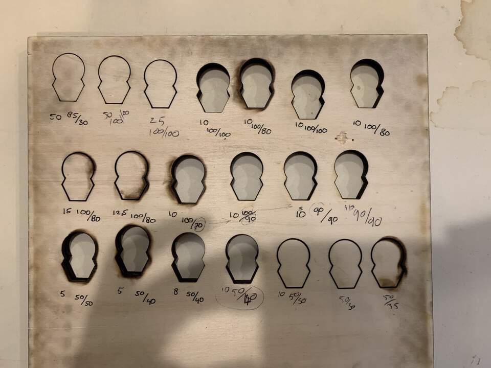
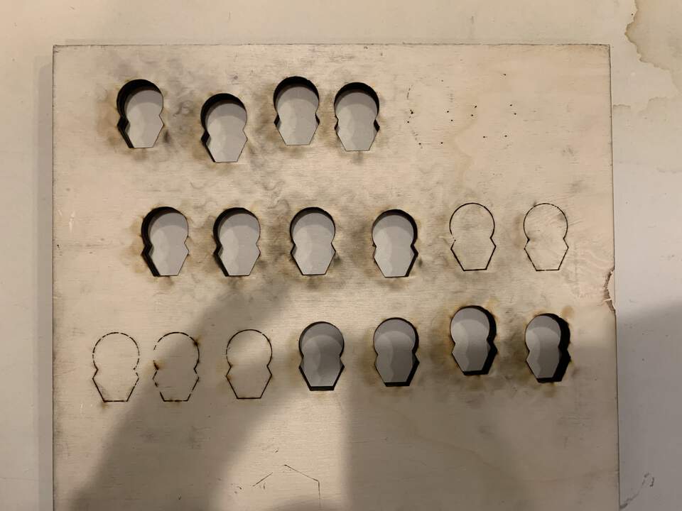
Material thickness: 9,02 mm, the thicker the material, the more random stuff can happen, the less nicer it will be. More thickness = lower speed.
| Speed | Max. Power | Min. Power |
|---|---|---|
| 50 | 85 | 30 |
| Does not go through |
| Speed | Max. Power | Min. Power |
|---|---|---|
| 50 | 100 | 100 |
| Corners done |
| Speed | Max. Power | Min. Power |
|---|---|---|
| 25 | 100 | 100 |
| Almost cutting lines to the back |
| Speed | Max. Power | Min. Power |
|---|---|---|
| 10 | 100 | 100 |
| Cuts outs, burnt back |
| Speed | Max. Power | Min. Power |
|---|---|---|
| 10 | 100 | 80 |
| Went very wrong, very burnt |
| Speed | Max. Power | Min. Power |
|---|---|---|
| 10 | 100 | 100 |
| We repeat it and we discover it was an anomaly cause it worked quite ok |
| Speed | Max. Power | Min. Power |
|---|---|---|
| 15 | 100 | 80 |
| A bit burnt |
| Speed | Max. Power | Min. Power |
|---|---|---|
| 12.5 | 100 | 80 |
| 10 | 100 | 70 |
| Burnt |
| Speed | Max. Power | Min. Power |
|---|---|---|
| 10 | 100 | 90 |
| Better front, still burnt back |
| Speed | Max. Power | Min. Power |
|---|---|---|
| 10 | 90 | 90 |
| 11 | 90 | 90 |
| Less burnt back |
| Speed | Max. Power | Min. Power |
|---|---|---|
| 5 | 50 | 40 |
| We tried changing the max power variable and it was burnt on both sides. |
| Speed | Max. Power | Min. Power |
|---|---|---|
| 8 | 50 | 40 |
| Quite well. More thickness = lower power + Max/Mn = medium |
| Speed | Max. Power | Min. Power |
|---|---|---|
| 10 | 50 | 40 |
| Best till the moment, corners could be lower -> in the end this one was the optimal |
| Speed | Max. Power | Min. Power |
|---|---|---|
| 10 | 50 | 30 |
| 10 | 50 | 30 |
| Just a few strings, holding pieces, minium too low. We repeat it to see if it was bad luck but it remains the same. This one does not work |
| Speed | Max. Power | Min. Power |
|---|---|---|
| 10 | 50 | 35 |
| Burnt back |
Measuring the kerf (after having calculated machine settings), offset.
Kerf: difference from what you draw and what the machine cuts out, laser eats material on both sides of the line. It is the measurement of space between the lines you cut.
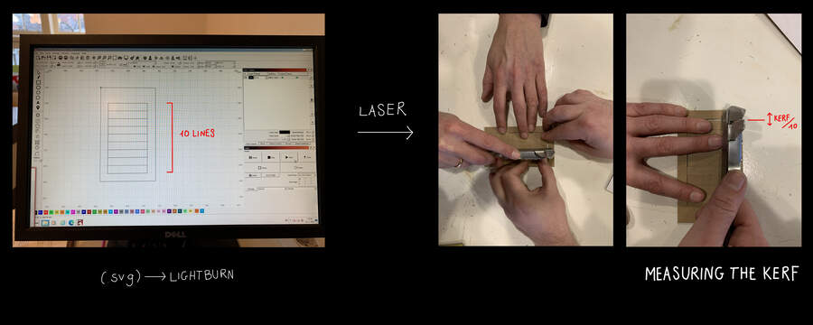
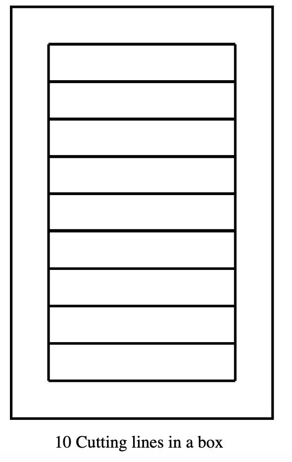
Procedure: - Drew 10 lines(0,001mm) x 2.5cm in between in Illustrator(.svg file) (no double lines or the laser will go through twice) surrounded by a frame. The idea behind it was that when we cut out the lines we could measure the space left between the cut rectangles and the frame to calculate the cut away material(x10). We did it 10 times so that our calculation would be accurate enough (as the kerf value is quite small).
-
Squish the remaining pieces
-
Measure the gap left between the squished pieces and the border
-
That gap value you divide it by 10
-
You get kerf value
-
We deduce the cardboard flex is 0,2mm
Offset: Where to place the centre of the cutting line if you want to get an accurately measured piece.
Offset = Kerf / 2
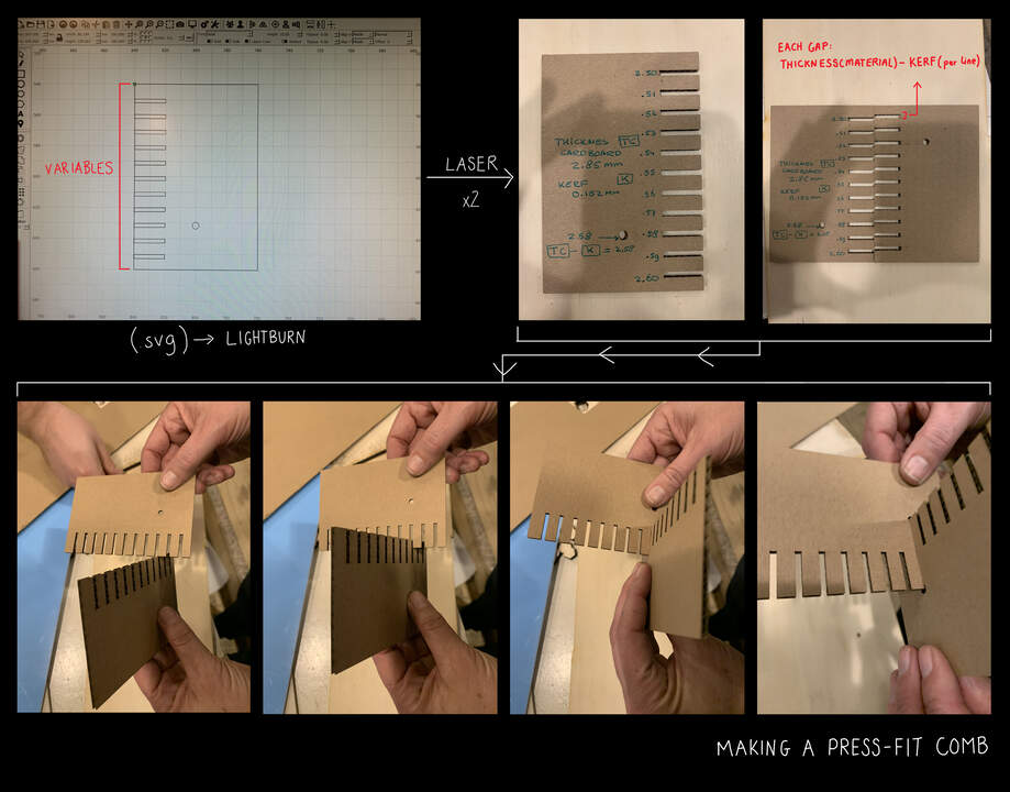
Making a press-fit comb (after having calculated the kerf and machine settings)
Clearance: The extra space beyond the offset setting to allow easy fitting when joining/fitting different parts. Male joint and female joint formula:
Total width = Desired Width + (2 * (Offset + Clearance))
-
The idea behind this was to find out the clearance needed to apply to joints (what is small enough that it will hold and not fall out).
-
We drew in Illustrator(.svg file) a comb with incremental varying widths from the formula:
Thickness material - kerf = Value for slot width
Which turned out like this:
2,85 - 0,152 = 2,69 (optimum value)
From this value we did varying widths going both ways(up and down) from our optimum value which was 2,69.
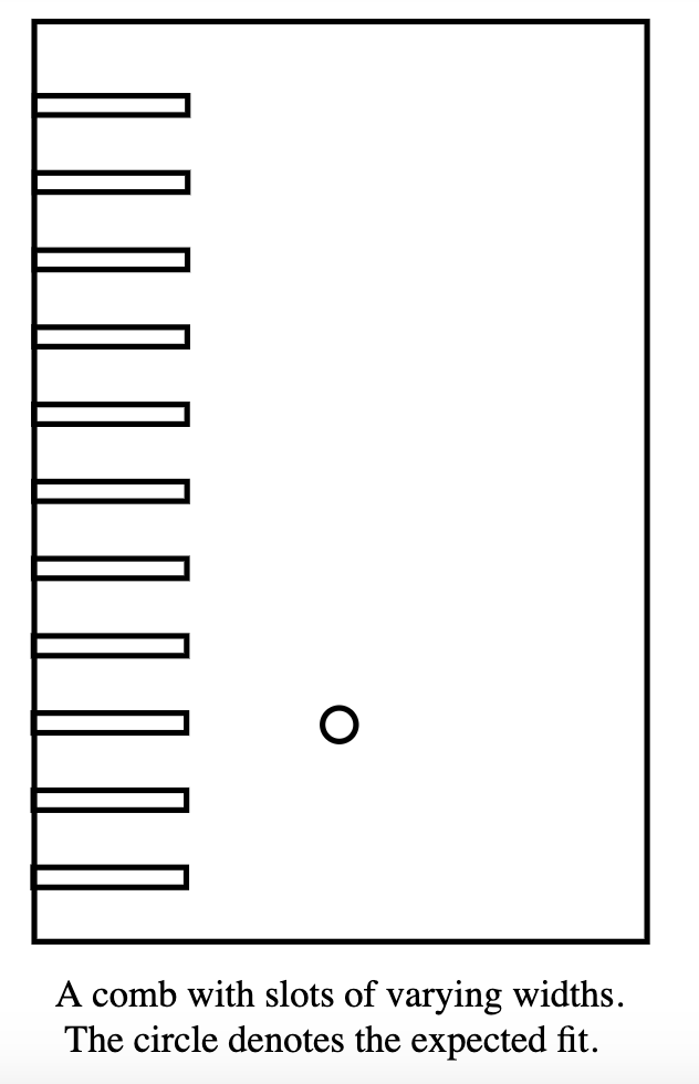
This would allow us to find the best width slot to press-fit the two parts, (the circle stands for our optimimum value)
We did the calculations wrong so the numbers written on the comb are wrong but the press-fit worked, we think it it because of the natural flex of cardboard!
Step 2: Individual assignment: design a parametric press-kit
Design, lasercut, and document a parametric construction kit, accounting for the lasercutter kerf, which can be assembled in multiple ways, and for extra credit include elements that aren’t flat.
-
you should make it parametric (VERY IMPORTANT), lower your expectations and make it completely parametric: this means that the geometric dimensions of the design can be easily varied and customised during the design process.
-
I will be given a 1m x 1m cardboard to make my design(always measure my material and check it with the previous group assignment task)
-
it can´t fall apart it has to be fit-pressed
First step: define starting point
I will be given a cardboard like in test 2: Cardboard 1, and although I will double check again machine settings when I cut it with laser cutter I know the cutting parameters will be similar than in here.
So I have a starting point of:
-
Thickness = 2,85mm
-
Kerf = 0,152mm
-
In order to get a press-fit we can play around (up and down) the value of 2,69 (2,85mm - 0,152mm = 2,69mm). This will make our press-fit precise and hold our pieces together without falling.
-
Machine settings for cutting cardboard 1: speed: 65/ mx. power: 85/ min. power: 40
Second step: draw 2D sketch of slot
-
Open Fusion360
-
Draw out the shape of my design.
-
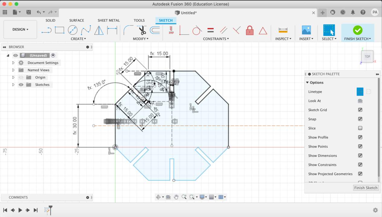
I first did a paper sketch to see what shape I could do. I calculated some parameters around it:
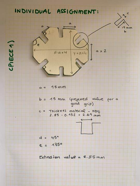
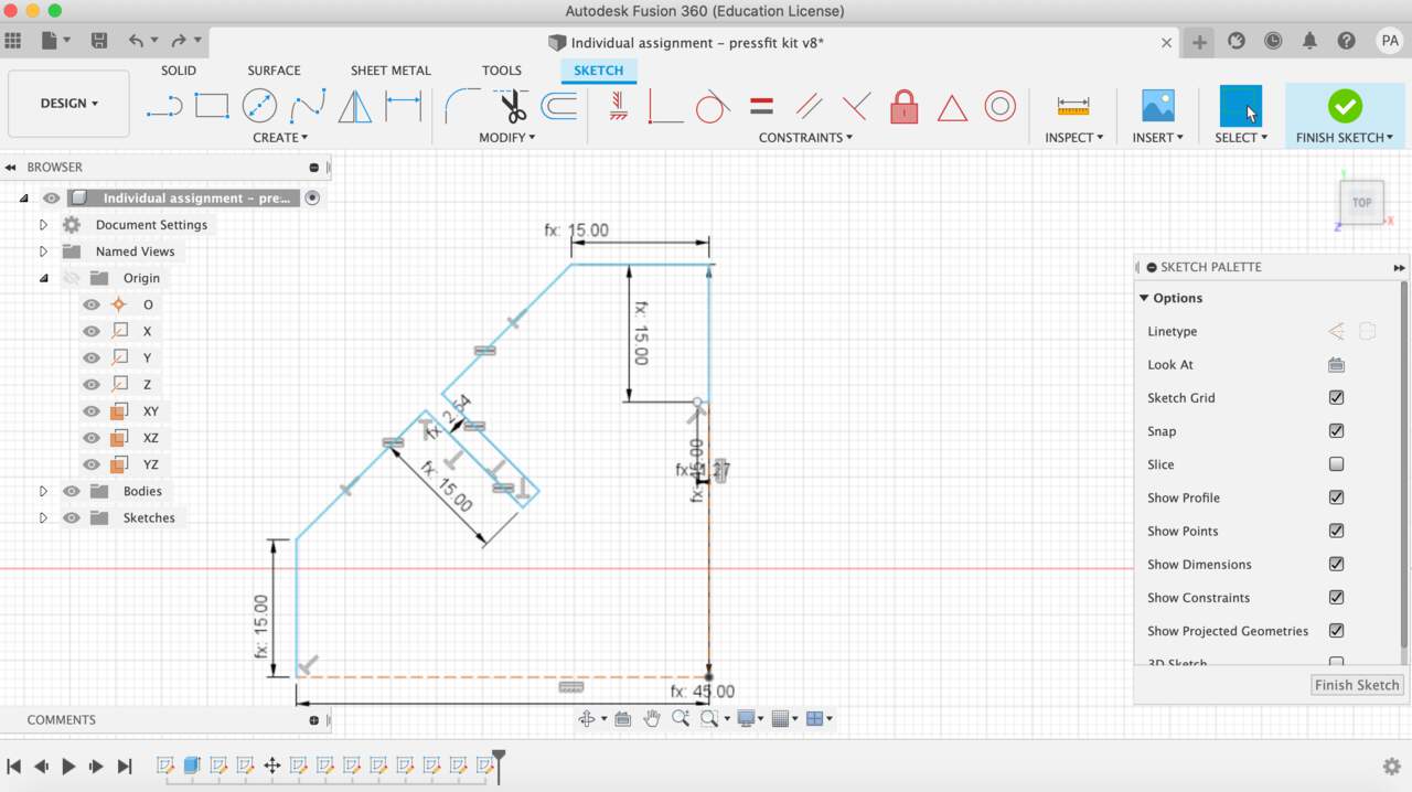
- Then I opened Fusion360 and created the parameters box.
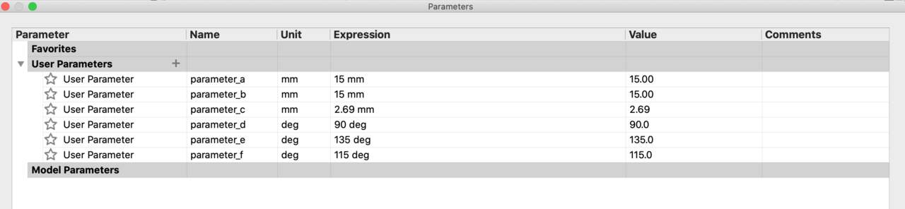
- After creating this I opened sketch mode and started to draw my shape. I drew a quarter of the shape setting up parameters for length and angle.
- I mirrored a quarter of the sketch
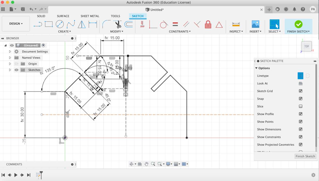
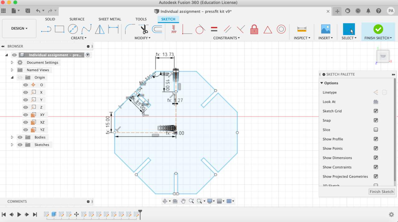
- Then I mirrored half of the sketch
- I extruded the shape with the cardboard thickness (I also created a parameter for this value)
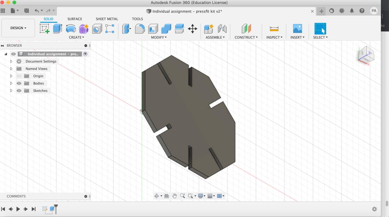
- My shape is done, I decided to do a very simple shape to learn properly about parametrics. Everything seemed so easy though! But problems came… I realised that I had mirrored just the lines and not the dimensions around it (parameters included) so when I changed the parameters this happened:
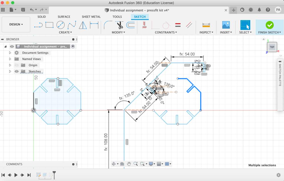
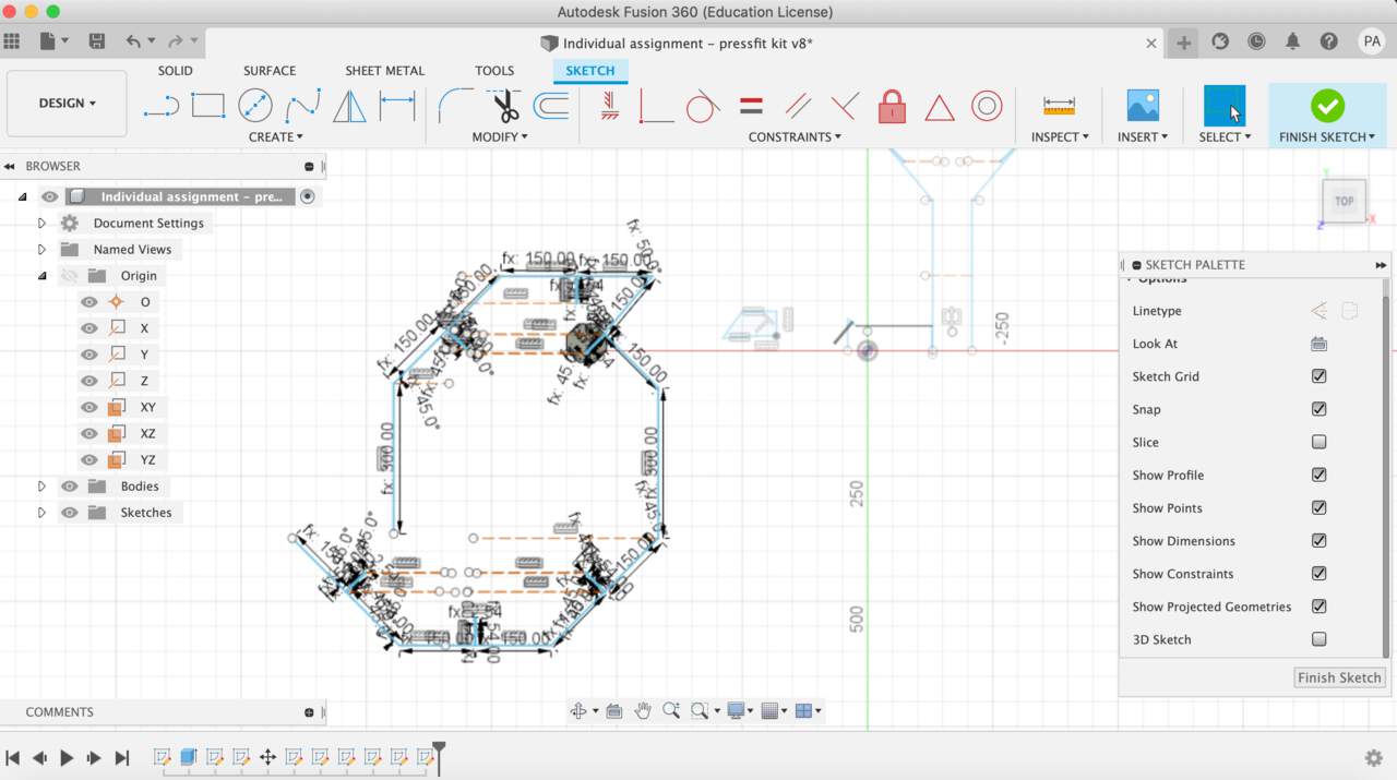
- My colleagues helped me out trying to constrain the whole sketch (apparently all lines have to be black in order for a shape to be completely parametric). I tried different ways of drawing it but none worked:
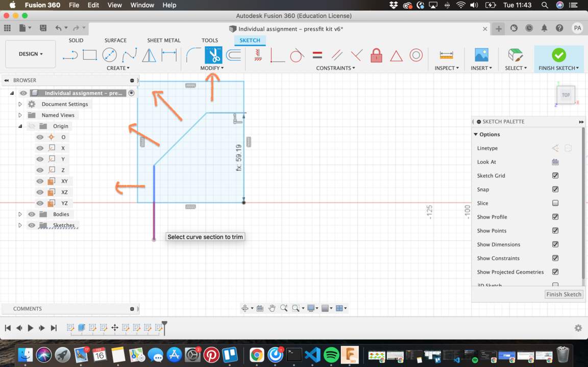
- So I decided to draw out the whole shape again without mirroring and adding every parameter line by line. This worked out parametric, I could change the values and it would remain the shape but what did not work were when I changed angles from the shape. This happened:
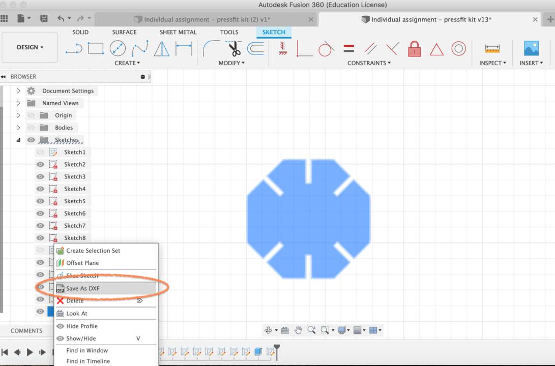
- I have not yet discovered how to make it with complete black lines but I will try to figure this out in the following weeks. The parameters I would want to change would work so I selected the sketch I wanted to export > right click > saved it as DXF and took it to my first try of laser cutting.
- I inserted the machine settings from the previous day and adjusted the manual focus.
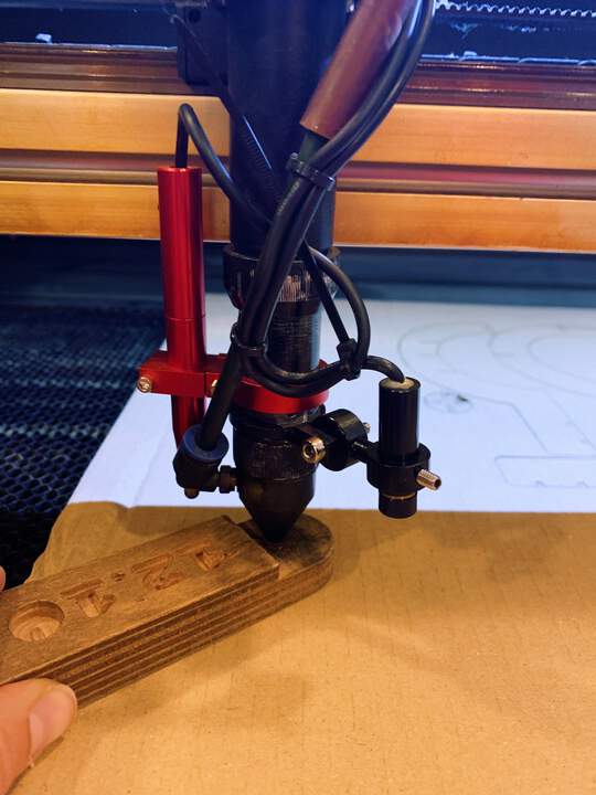
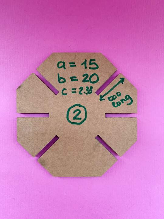
- On my first attempt of laser cut I realised the slots were too wide.
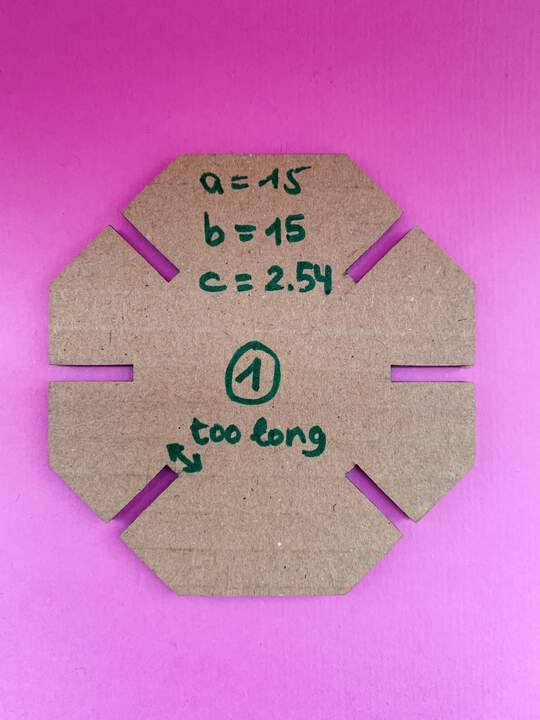
- I realised the width of the cardboard was not the same as the first day, instead of 2,85mm it was 2,69mm. So in my parameter table I changed the slot width (parameter_c). The formula I did was:
(2,69 - 0,152 - 0,2 (flex cardboard value) = 2,38
I also changed the length of the slot depth (parameter_b) to see if they would hold better like this.
-
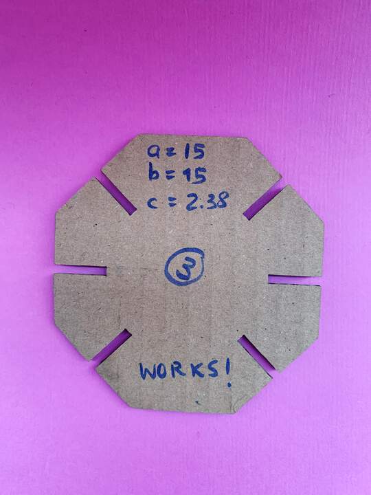
After cutting it I realised the slot width was perfect (it would grip good) but the slot depth was too high because, when fixed together, the pieces would bump into each other.
-
So I changed again the parameter_b to what it was (15mm)
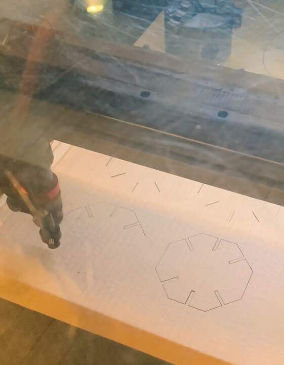
-
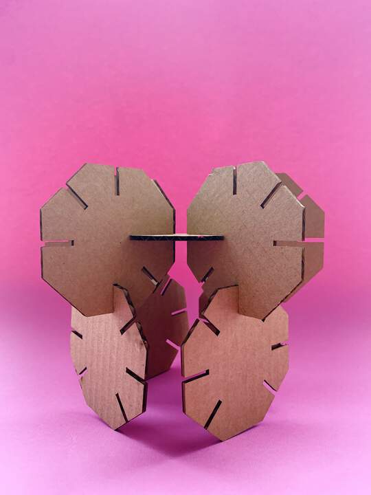
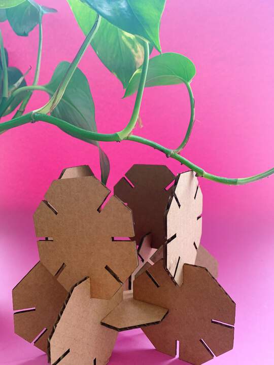
The third try was a success:
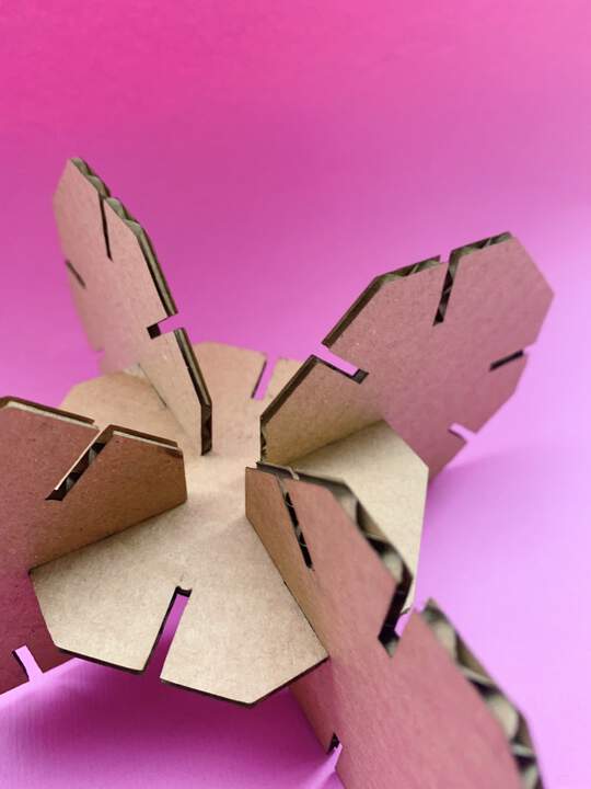
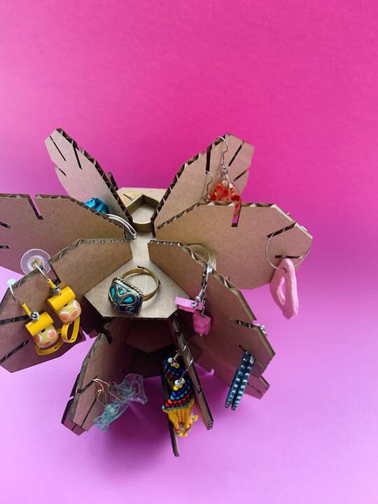
- There are multiple ways of assembling them but for now I have decided to hang some of my earrings on it :)
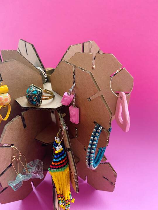
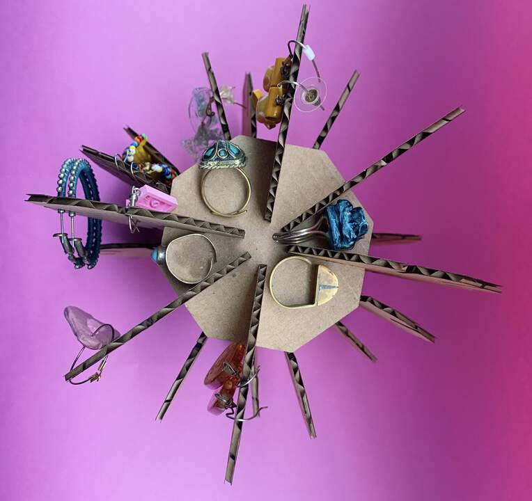
Other shapes:

Characterize (describe/understand the nature and features (of your particular vinyl cutter)
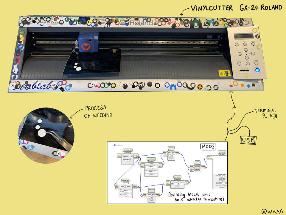
The computer, through the vinyl cutter, controls the movement of a sharp blade over a material. You can cut out letters and shapes from sheets of one-colour self-adhesive plastic(if you want multicolor designs you have to cut it out into different coloured sheets and stick one on top the other). You can stuck these to different surfaces, depending on the vinyl.
Some commands to use the vinyl-cutter from terminal:
echo hello
echo PD > /dev/usb/1p0 (pins down the knife)
Machine starts, pin down.
echo PD 100,0 > /dev/usb/1p0 (X,Y values = the machine cuts)
You can also directly talk to the machine through Mods.
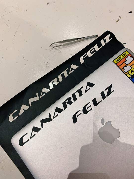
Creating a vector drawing in the vinyl-cutter:
I am going to create a sticker for my laptop to test the vinyl cutter. These were the steps I took:
-
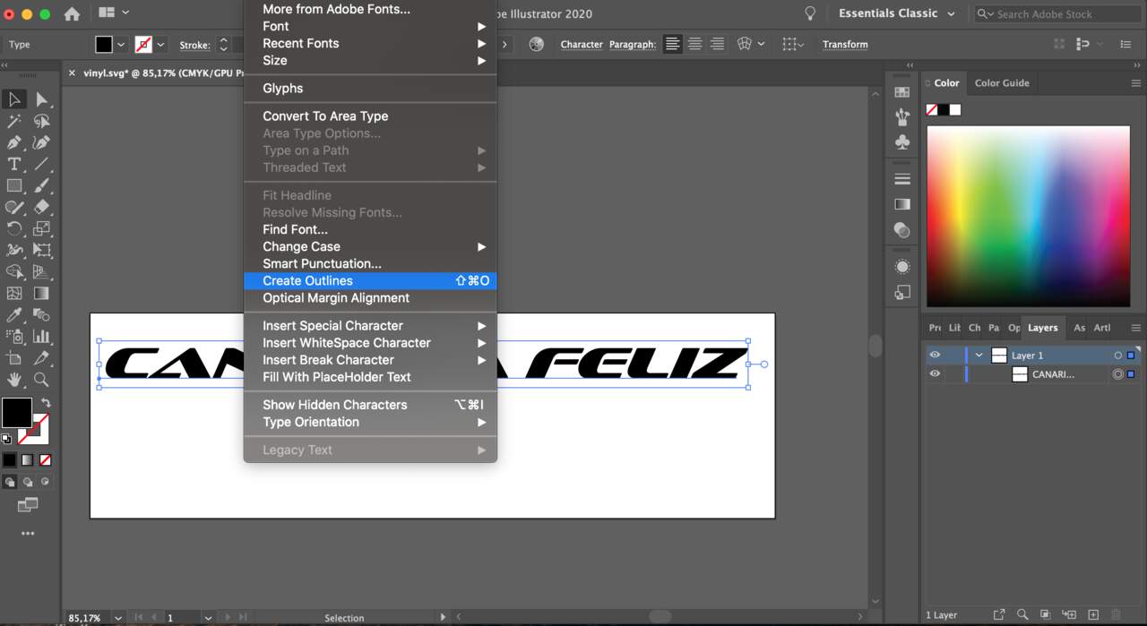
First I drew a simple text in Illustrator.
-
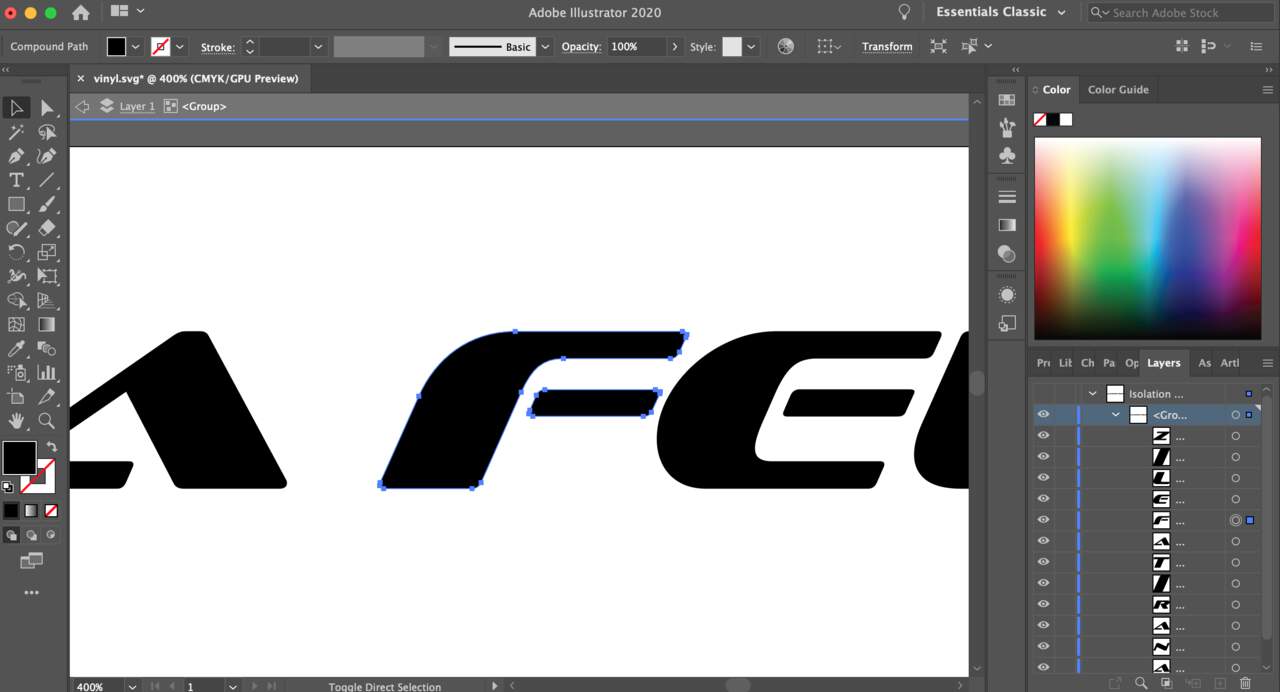
Then I outlined the text so the vinyl cutter could trace the lines.
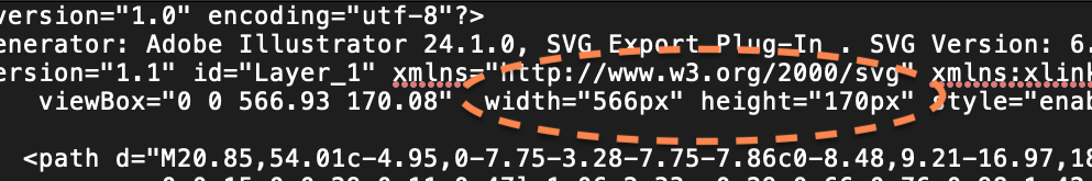
- I saved the file as svg and opened the file with Text edit and introduced the following settings (the same dimensions as in Illustrator):
-
Saved the svg again, saved it in a usb and introduced the usb in the computer by the vinyl cutter.
-
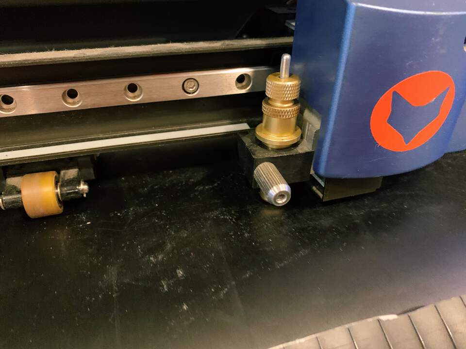
Lucia showed me how to load the vinyl to the machine, first you put the handle down, introduce the vinyl through and put the handle back again so it holds the vinyl in place.
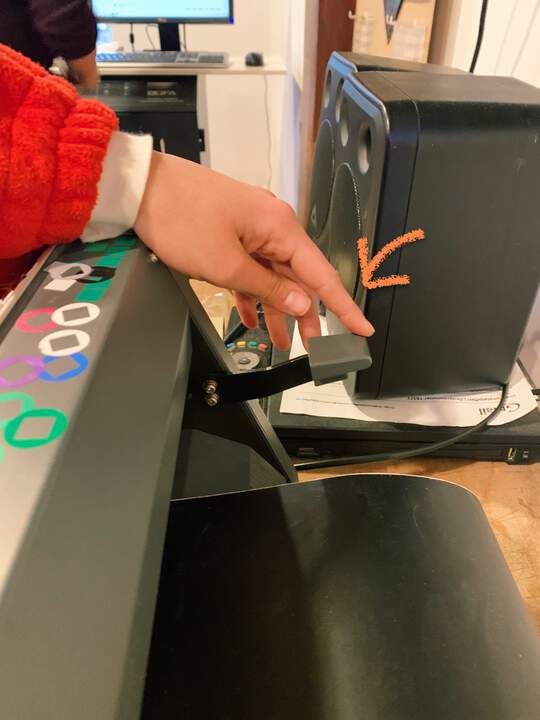
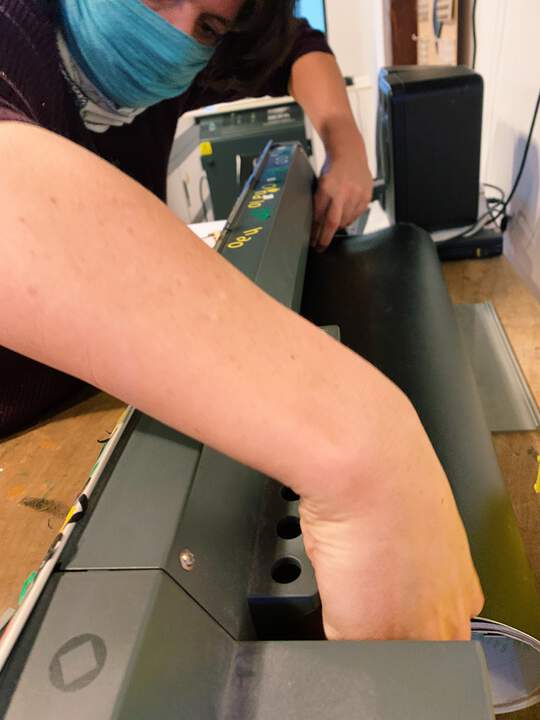
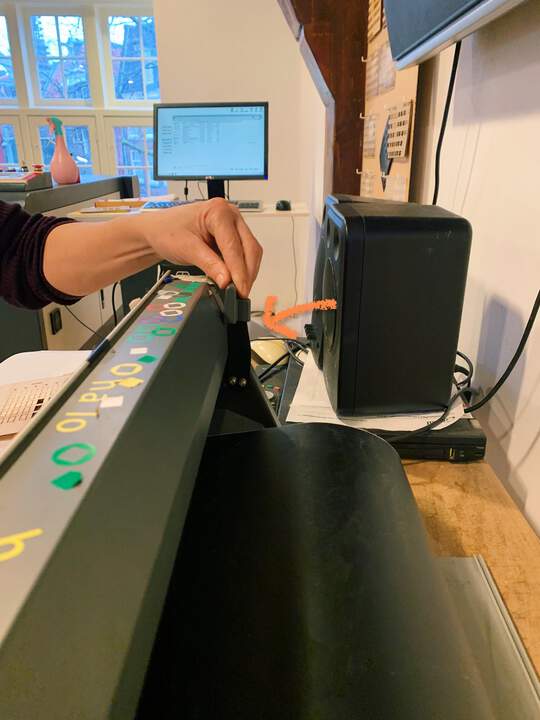
-
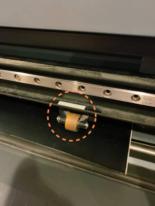
You have to check the wheels are by the white stickers:
-
You turn on the machine
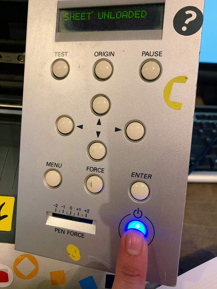
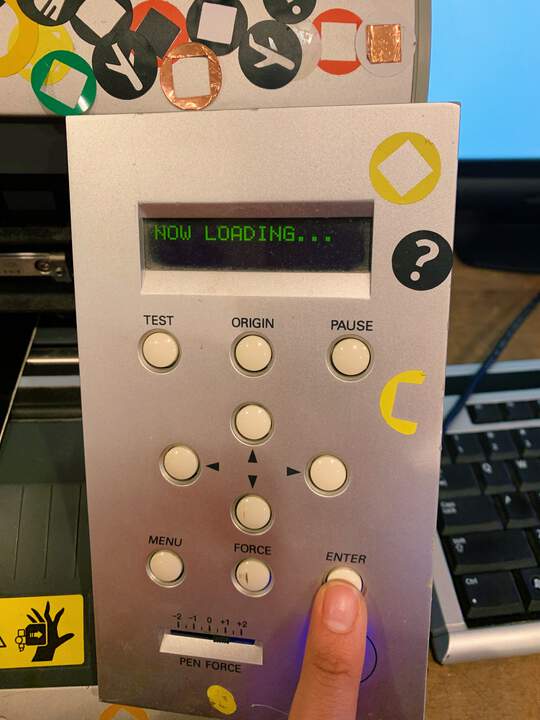
- You press test so the machine goes through the material (it will ask for it if it is not there)
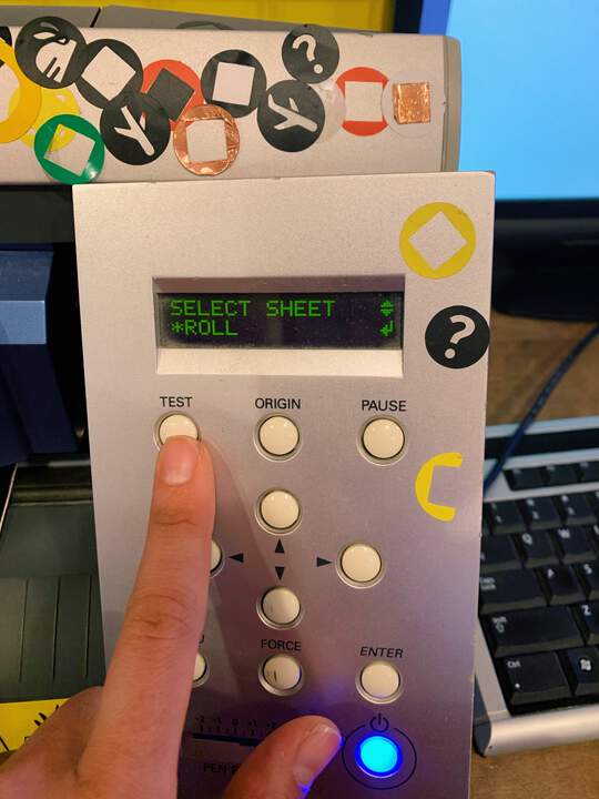
- Then you press enter.
-
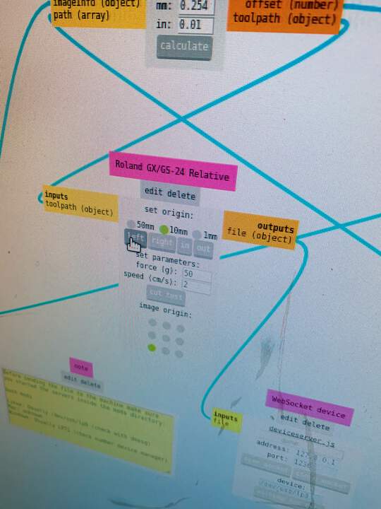
Open mods > right click on menu > programs > open program > Roland GX-GS > cut
-
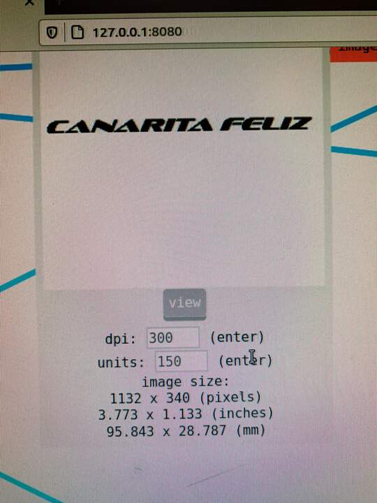
This page will open up:
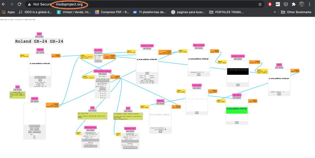
-
You will have to upload your svg file here.
-
I changed the size of the sticker in mods. I realised that higher units means smaller sticker. I did it twice till I found the perfect size.
- You can also move the machine through this panel:
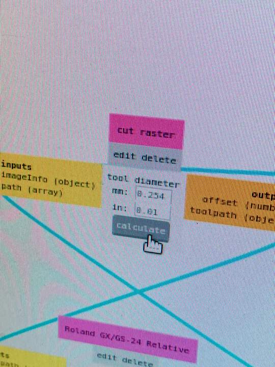
- With every change you make you have to press calculate button again:
- When your file is ready press:
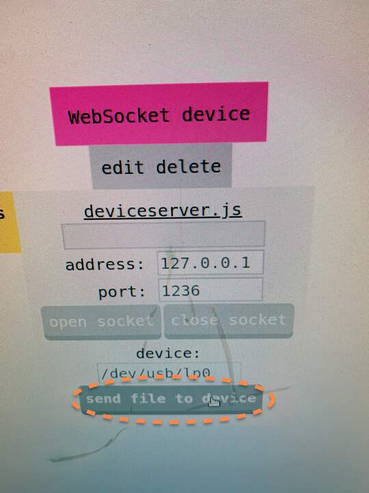
- The machine cuts your svg file:
- Then you take out carefully the sticker by the process of weeding:
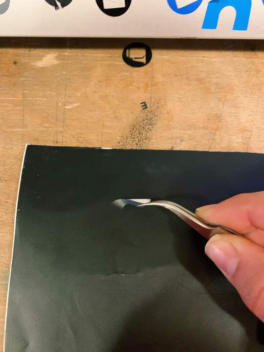
- Sticker done!
Files to this week’s assignments:
- This is 3D.STL file for the design I made | 3D.stl