Week 10: Input devices
The second half of the Fab Academy programme is designed to build on the previous weeks. You will be synthesising information and implementing skills that you were introduced to in the first half of the programme and encouraged to integrate these into your final project proposal.
Assignments:
-
Group assignment: Probe an input device(s)’s analog and digital signals. Document your work (in a group or individually).
-
Individual assignment: Measure something: add a sensor to a microcontroller board that you have designed and read it.
What to learn:
- Demonstrate workflows used in sensing something with input device(s) and MCU board
Have you?
-
Linked to the group assignment page
-
Documented what you learned from interfacing an input device(s) to microcontroller and how the physical property relates to the measured results
-
Documented your design and fabrication process or linked to previous examples.
-
Explained the programming process/es you used
-
Explained problems and how you fixed them
-
Included original design files and source code
-
Included a ‘hero shot/video’ of your board
DOUBT: What does “probe” mean? Answer: A test probe is a physical device used to connect electronic test equipment to a device under test (DUT). To probe means to measure, observe or monitor signals with test probes.
DOUBT: Is the satsha kit/fabduino I fabricated considered a valid board for this assignment?? Answer: Fabricating an unmodified board is considered as electronics production. It doesn’t count towards any design skill. You must make some significant changes to the original satsha kit/fabduino, for the board to be considered your own design.
DOUBT: Can I use a breadboard and/or jump wires to interface my input device(s) Answer: No. You can’t use a breadboard. If you use wires, they must be soldered or connected with connectors.
What is an input device?
An input device(sensor) responds to changes in the environment and produces an electrical signal within an electronic circuit. Sensors are all sorts of ways to measure inputs, they perceive other forms of energy which are then transformed into electrical energy.
When choosing a sensor there are different parameters which are considered:
-
Type of sensing: what is the sensor measuring.
-
How does the sensor work?
-
Power consumption: how much power does the sensor consume, this is important when determining the total power of the system.
-
How accurate is the sensor? Do you need ppm values or just simple sensing?
-
Where is this sensor going to be placed? This helps to choose the quality needed for the sensor.
-
Cost of sensor: depending on the application you will give to the sensor you can choose from low and high cost devices.
-
Resolution and range: this is the smallest value that can be sensed and the limit of measurement.
-
Calibration and repeatability: change of values with time and ability to repeat measurements under similar conditions.
If you open the ATtiny 412 datasheet you can see there are multiple ways of getting inputs to it:
-
One of them is through the pin (shown in page 106), each pin is a little machine. Each pin can be an input listening or an output talking, if its an output talking there is a pull up resistor you can use to hold the pin high unless you externally pull it low for example with a switch.
-
The comparator compares two voltages; if one is above or below the another. You can do it very quickly, to check for example a battery below a threshold.
-
In page 253 from the datasheet it shows the analog to digital converter: we will use this a lot: this ADC, you have an analog voltage that comes in, depending in the processor it can be either single ended or double ended meaning it will measure a voltage betweeen two voltages, depending on the processor you can amplify the voltages and there is a clock that drives the cnversion: use the clock to trade off how quickly you convert vs how accurately you convert. You can make multiple readings that improve the signals noise. (There is a lot of options to read the ADC).
Communication with input devices:
For this week we have to read a signal and communicate it out(from the chip to the PC you need to communicate and vcvs). All the following let you talk with the IC and see what signals are coming in:
-
In the Arduino there is a serial monitor that tells you what is coming in.
-
PySerial is the interface between python and serial, it has a terminal which tells you what is coming in: miniterm, these are two really simple scripts to communicate rx.py(prints out the raw data coming in) and term.py
Neil also mentions that something to be aware of is time: one of the things that can happen is that you connect the processor to computer, send data in, and the processor starts sending characters but they look like garbage. If we see this we should connect the processor to an oscilloscope or to a logic analyzer and look at the timing(duration of the bits). This is because we have to be aware that if we are doing serial communication we need to match the bit timing(if we use a processor with hardware USB this is part of the USB peripheral).
Type of input device: switch
-
Button: normally it is open and if you push it it’s closed.
-
Slide switch: the center pin gets connected to one side or the other, based on the position of the switch, one is momentary, one keeps its position.
How to read a button?
-
This is the simple example of pushing a button, and if I push the button it tells me when it goes down and when it goes up. In this case the circuit has a ATtiny45 chip which is connected to one of the pins of the button and talking out through the serial port.
-
In this example the serial port is set to talk out the button as an input with the PULLUP turned on, which means that there is a processor and a switch going to ground; when it is closed it is the ground but when it is open the voltage is not specified, so you can turn on an internal PULLUP resistor(inside the chip) that holds this high unless you close it.
Something to be aware of, is debouncing: from Quora I got this exaplanation for it: “debouncing is the method of reducing the oscillations following a step input. This mostly applies to a key or switch press.”. Neils explains this as in code while I am communicating it is making the bouncing = quick transitions, when you read a button at the first transition you need to wait a delay before you try to read it again for the reading to be valid so this is debouncing.
-
This same example as above is a button going to the ATtiny 412: the code does the same thing, I read the button, I read out the character, I write the button and put out a character, this uses an arduino library. This second code does the same thing but without the arduino library. It has all the code here, it is not using the hardware communication peripheral but rather generating the communication in the software which means you can do it on in any pin, looks more complex but you do not depend on external arduino libraries (and pins can do much more without the libraries).
-
The difference with the D11C does the same thing but the big difference is it is a 32 bit processor with and ARM core and it is built in USB.
Type of input device: motion
-
The pyroelectric: measures thermal radiation in your body. Example codes can be found here
-
The doppler radar is more recommended for newer designs of motion detection as it is very responsive. In this video example it shows how as soon as someone moves it knows it is there, it is a very good sensor for proximity. Example codes can be found here
Type of input device: distance:
-
Optical sensors are more recent and powerful devices as they are laser range finding, it sends out a light pulse and measures the time for the pulse to come back(in picoseconds, incredible small time). They also come in modules and they have their own library. Example codes can be found here
-
Sonars are also distance sensors which put out and acoustic pulse and measure the time to come back. Example codes can be found here.
-
Lidar are also laser range finding.
Type of input device: location sensors, time:
Location sensors work with the satellites that fly over the earth, each satellite tells position and then you measure the time to satellite by measuring the time delay. Types of location sensors:
-
GNSS navigation systems
-
NEO-6 these are modules that talk to GPS, they are very good.
-
GT-U7 module, these are 10 dollar modules with antenna for sensitivity.
Type of input device: magnetic field:
-
Hall effect sensor: this is a semiconductor device, current flows through it and you get a voltage across it which is proportional to the magnetic field. Example codes can be found here.
-
If you look at the ADC there are multiple things you can set, depending on the processor, you really want to configure the ADC to talk to it directly.(not using a library, directly telling the ADC what to read).
-
This video: shows a vector measurement, if you flip the circuit around it goes in the other direction. If he takes the magnet and flips it you can even still see a 1 digit change, which is because of the earths magnetic field, this sensor is so sensitive you can even use it as a compass.
-
In this code what Neil is doing here is oversampling which is that you read the ADC, but not just once but 100 times (by defining in the code n samples 100) and the accum at the top is 32 bit varible, bigger size variable, means each time i read the ADC it add the result to the accumulator, so by reading it many times I improve the resolution.
-
This whole sensor is useful for the proximity of a magnet, this is handy for example if you want to have a lid closing sensor, or an end stop on a machine, or know when a door is closed.
-
The array has 5 more sensors in it, used in joysticks, gives 3D position
Type of input device: temperature:
-
Their resistors depend on temperature, they work in 2 different ways, resistance vs temperature, they go in opposite ways. Which one you use depends if you are going down in temp or up in temp, you read these by using a bridge. Example codes can be found here.
-
Most of the chips we are using actually have a temperature sensor built into them, if you look at the datasheet and configure the ADC you can measure the temperature of the chip.
Type of input device: light:
-
You can use LED as a light sensor.
-
But normally we use phototransistors:IR and visible a transistor where the current is proportional to the light intensity. Example codes can be found here.
-
Synchronous detection spread spectrum: these substract out the room light and just gives me the bouncing light from the LED.
-
Color sensors [example of RGB sensor]((http://fab.cba.mit.edu/classes/863.19/CBA/people/jiri/week9/index.html) these are 3 light sensors, lets you measure colour with a digital interface.
Type of input device: acceleration, orientation, rotation:
-
3 axis accelerometer measure acceleration in 3 axis, it is a digital interface: sending digital messages to it, most of these parts are normally designed for dense packaging so the pads are underneath, to use them you have to do reflow, easiest way is hot air gun. Example codes can be found here.
-
There is also the 6 axis accelerometer+gyroscope:
Type of input device: sound
MEMS microphone has a transistor in it. It has two types of interfaces to talk to it:
-
digital: mems microphone digital (best one), strongly recommended.
-
speech modules these are emerging and evolving, chips to make embedded voice recognition.
Type of input device: step response:
- This sensor lets you measure resistance, capacitance, inductance, position, pressure, force, tilt, acceleration, humidity, proximity, touch, multitouch, bending, … It is a very good sensor to look into. Example codes can be found here.
Type of input device: vibration
- This piezo measures vibration.
Type of input device: force
-
This force sensing resistor can be used to measure force but they are quite messy and noisy
-
The strain gauge is the standard way of measuring force by measuring resistance on a foil
-
The load cell has a strain gauge on a beam that bends
-
The capacitance you can make a capacitance sensor
Type of input device: angle:
- This sensor measure angular position
Type of input device: pressure:
- This sensor measures air pressure.
Type of input device: pulse:
- This sensor measures heart rate and pulse oxygen by reflecting infrared light.
Type of input device: air pollution:
Type of input device: gases:
Type of input device: image processing:
-
There are a lot of camara modules. The ESP32-CAM combines the ESP bit processor with a camara, they sell them for 10 dollars in a module.
-
There are also webcams: doing the same thing as before by putting video into a webpage. Example codes can be found here.
Group assignment: Probe an input device’s analog levels and digital signals
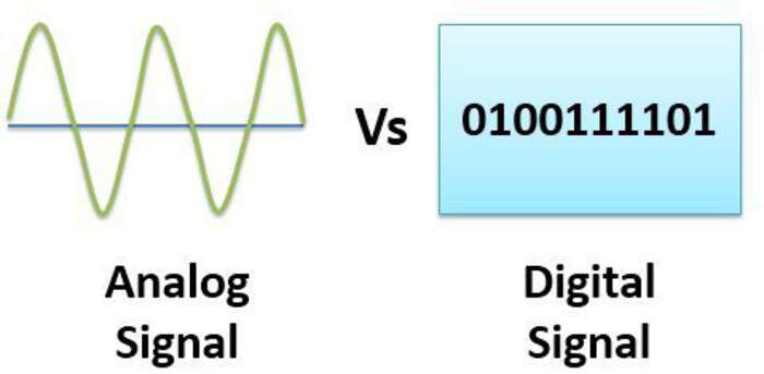
What is the difference between analog and digital signals?
I started understanding the difference between analog and digital signals. From this source I learned that:
-
An analog signal is a continuous signal in which one variable(like voltage, pressure, etc.) represents another variable = one variable is an analog of the other. This allows for infinite number of values to be represented. For example “imagine a dimmer switch tied to a light bulb. In a perfect analog system, the dimmer will have an infinite number of positions between “off” and “full” – and a correspondingly infinite number of levels of output by the lightbulb. The output by the bulb is analogous to the time-dependent variable “position of the dimmer switch.” The analog allows much more options.
-
Digital signals express variation in the system’s variable in response to a set of discrete values (more like a light with an “on/off” switch or a three-way bulb with multiple, discrete levels of output).
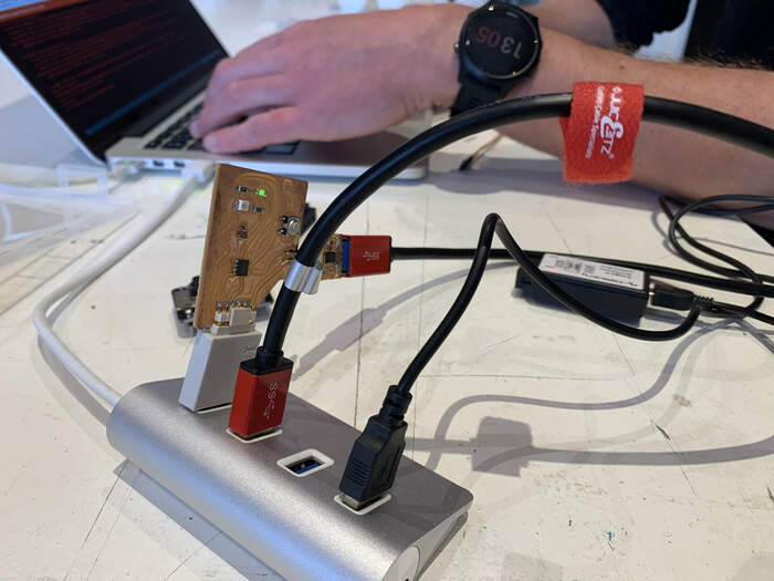
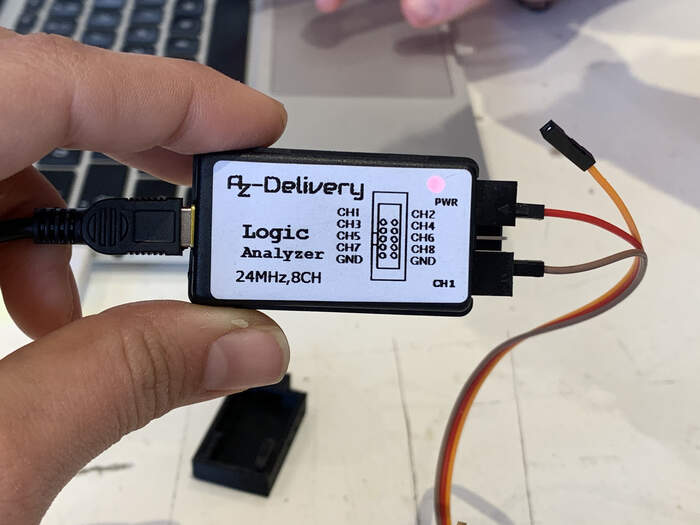
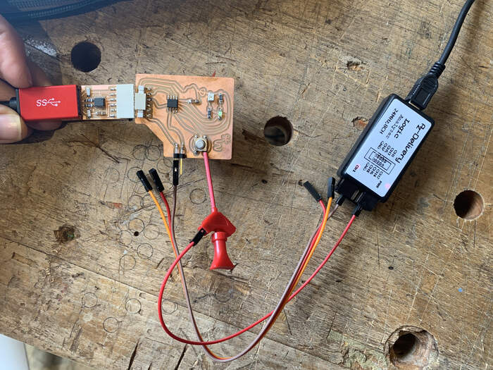
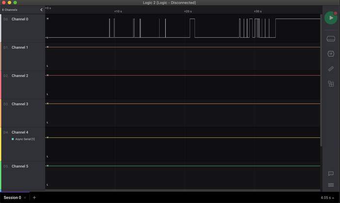
In our group assignment we had to understand how to use a logic analyzer. We first saw a video explaining the small and cheap logic analyzer, SPI i2c UART. The idea of using the logic analyzer was to measure and analyze the data of the signal coming from the ATtiny of our hello echo world board.
- We first connected the hello echo board from Douwe to his computer with the UPDI and the FTDI. The first thing to do is to load some program on the board so we can read some kind of signal with the logic analyzer, we will do this with the UPDI connection.
-
When connected we opened the Arduino IDE. We select a basic button code from the Arduino library, connect the LED (ledPin=0) and the BUTTON (Buttonpin=A3). This resulted in an LED turning on and when you maintain the button pressed it will turn off. We did not worry too much about the code as the only thing we wanted was to read the signal coming from it.
-
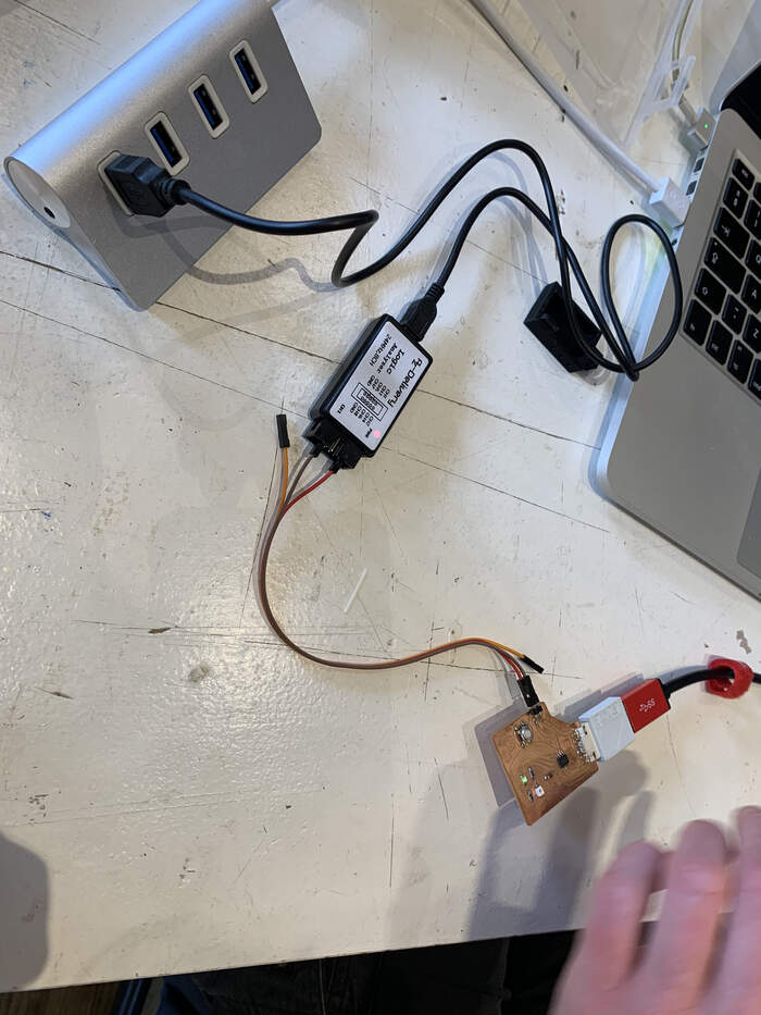
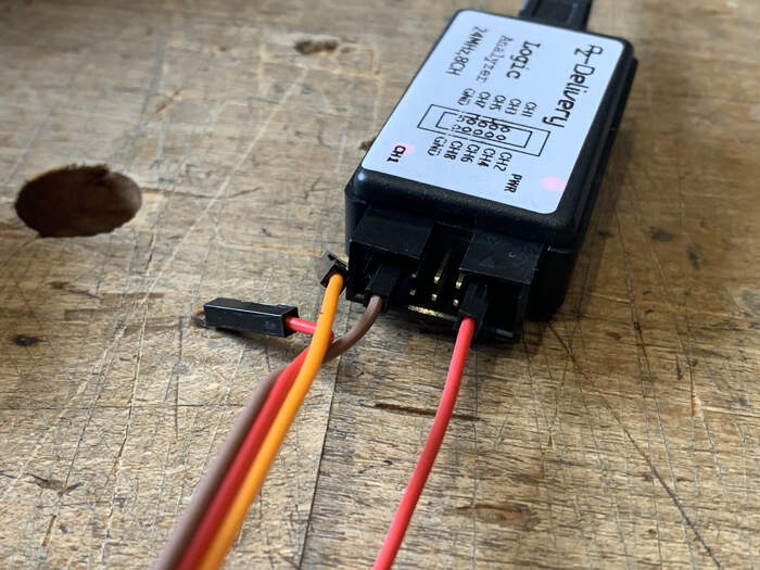
We removed the UPDI because it is only for programming and just leave the FTDI for power. Now we get the logic analyzer, you connect the cables following the sticker:
-
We open Logic 2 software too. Then we select communication protocol I2C, learned it from here. But nothing is working so we select Analyzer Async Serial and we choose Channel 1. We push the button from the echo hello world but nothing is showing. It is also showing up an error during capture “memory of chip is full”.
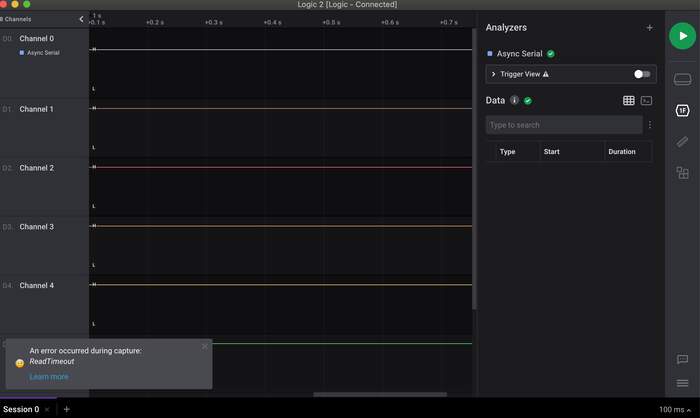
-
Later on Henk explained this is a common error we don’t have to worry about. We also discover that in Logic channel 1 is channel 0 on the logic analyzer. We still don’t have any signal coming up. We tried changing the FTDI cable = nothing appeared. We used another logic analyzer = same error. We used Philip’s echo board = same error. Maybe it is the software?
-
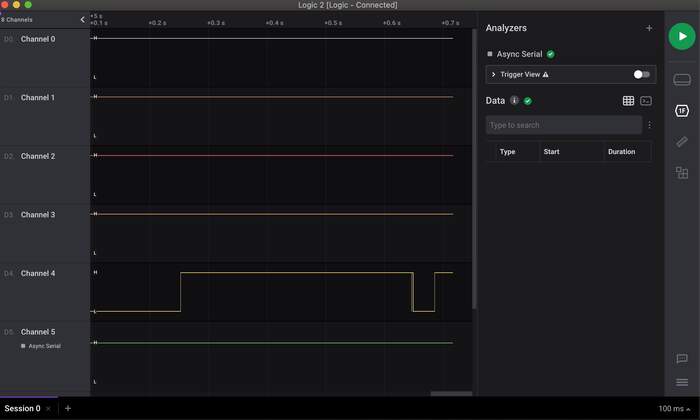
We then connected the whole thing in my computer but we still had the same error. I downloaded the software from here. I tried changing the channel from the pins connected to the Logic analyzer to see if all the channels did not work. After a while trying new things I learned that in order to connect to the board we had to connect the cables from the logic analyzer to one of the components that was giving out signal (like the button). So we connected the button with pins:
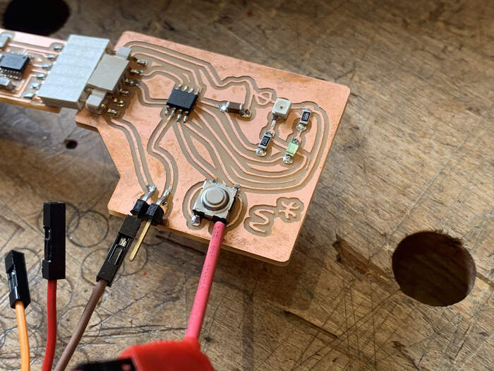
-
We now start to see the signs we were looking for:
Individual assignment:
Choosing a sensor
-
For our individual assignment we have to design a new board as the one we did for our Helloechoworld board was designed by Henk. This way we will also get used to designing from scratch. I have thought of making a gas detector for propane to detect propane leaks in my campervan.
-
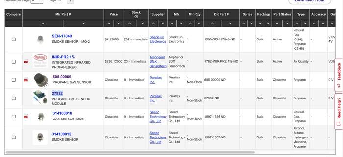
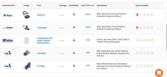
As I did not have any idea of where to start from I first searched in Digi-key for propane gas sensor.
-
Some of the examples I looked into were obsolete. Then I looked into the gas link from Neil’s, this refers to the MQ-2 gas sensor. After reading documentation from different fablab students I assured myself MQ-2 would be the right sensor to use.
-
I asked Henk if we had this type of sensor at the lab, he explained that to order on Digikey you had to do it as a company. At the lab we had the MQ-9 and MQ-4 sensors but these do not sense propane so he ordered MQ-2 which would arrive on Tuesday/Wednesday.
Reading about the functionality and use of the gas sensor
Some of the questions that arised in the first place where:
-
How to connect the sensor to the ATtiny?
-
What is the maximum operating voltage of the sensor?
-
How can I know what is the right microcontroller to use?
-
How do the gas sensor pins need to be connected?
-
In Digikey there is no datasheet for the MQ-2 Where else can I find it?
-
How to know from a component what is neccessary to create the circuit? Where to start from?
On Saturday I also connected to the Global Open Day session where I got some very helpful tips and explanations:
-
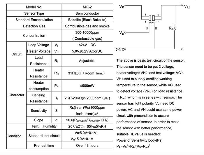
I was not sure if the MQ-2 datasheet was the right one as I had not find it in Digikey but they said it looked fined and also they shared this datasheet with all MQ sensors.
-
They also explained that I could also use modules for the MQ-2 sensor as it is easier because these have built-in circuits within them so I do not have to worry about making the “sensor-circuit” myself. This is an example for a MQ-2 module. I asked Henk if I could use one of these instead but he said the MQ-2 sensor was already ordered and the idea of this week is to learn how to figure out the circuit. So I went for the challenge! I also found out that “When it comes to measuring or detecting a particular Gas the MQ series Gas sensors are the most commonly used ones. These sensors can either be purchased as a module or as just the sensor alone. If you are trying to only detect (not measuring ppm) the presence of a gas then you can buy it as a module since it comes with an op-amp comparator and a digital out pin. But if you planning to measure the ppm of a gas it is recommended to buy the sensor alone (without module).” The information I got from this source confirmed that as I wanted to measure the ppm(part per million) of the gas it was preferable that I used the component alone. “If you are looking for some accuracy with your readings then measuring the PPM would be the best way to go with it.”
-
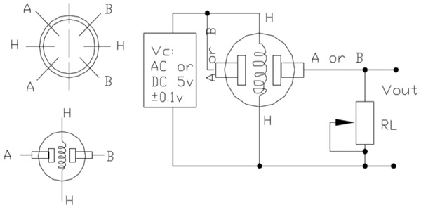
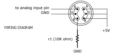
They also explained that to set up the circuit to use the sensor you had to look at this simple sample circuit image in the datasheet: which explains the type of connections to the pins needed, including required/associated components:
-
Basically what I understood is that I had to create a “board” for the gas sensor and then a “board” for the microcontroller which would program the sensor(UPDI). These two board would actually be one board and it should also receive power (FTDI).
After reading the datasheet of the MQ-2 some features I understood were:
-
High sensitivity to LPG, Propane and Hydrogen
-
Long life and low cost
-
It had a simple drive circuit
It’s application was also suiting my goal:
-
Domestic gas leakage detector
-
Industrial Combustible gas detector
-
Portable gas detector
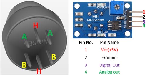
Then I also found this pinout images which were really helpful to better understand how to connect the pins:
-
“A and B are the input and output terminals (these are reversible - means any of the paired terminals can be used as input or output) and H is the Heater coil terminal. The purpose of the variable resistor is to adjust the output voltage and to maintain high sensitivity. If no input voltage is applied to the heater coil, then the output current will be very less (which is negligible or approximately 0). When sufficient voltage is applied to the input terminal and heater coil, the sensing layer wakes up and is ready to sense any combustible gases nearby it. When the sensing layer interacts with the gases, the resistance of the material varies and the current flowing through the circuit also varies. This change in variation can be then observed at the load resistance (RL).The value of load resistance (RL) can be anywhere from 10KΩ to 47KΩ. The exact value of the load resistance can be selected by calibrating with the known concentration of the gas. If low load resistance is selected then the circuit has less sensitivity and if high load resistance is selected then the circuit has high sensitivity.”
-
From here I understood that 1 of the B pins is connected to one of the analog input pins from the chip. “When it comes to measuring the gas in ppm the analog pin has to be used, the analog pin also TTL driven and works on 5V and hence can be used with most common microcontrollers.” Source
-
The other B-pin is connected to ground through a resistor. The load resistance is adjustable so I will have to decide on this later on.
-
The A-pins are both connected to VCC.
-
The H-pins are one connected to VCC and one to GND.
Basic interfacing of how it works:
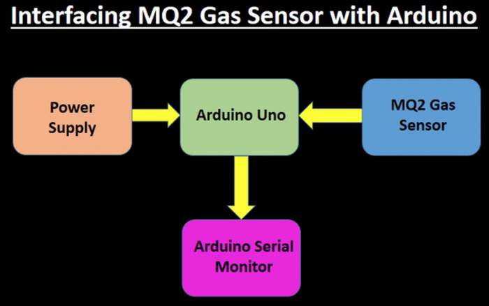
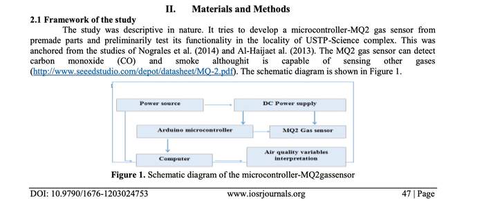
The best source I found about the MQ-2 was this one. It had most of the information I needed to know.
This source also helped me understand how the gas sensors work. It also compares gas modules vs non modules circuits.
Another question arised which was: What output pins would I include in the board? to indicate there was too much propane in the air?
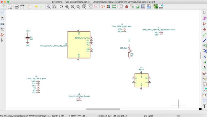
Designing schematic
-
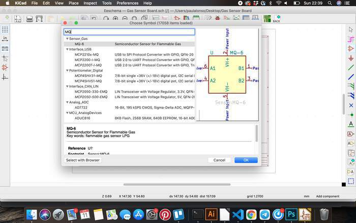
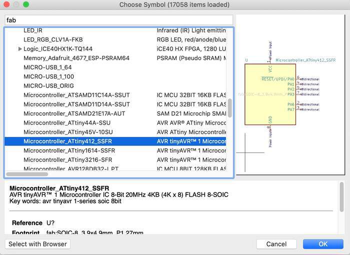
I opened Ki-Cad schematic, created a new project and I looked for the MQ-2 sensor symbol. There was none.
-
I then looked for the symbol in Snapeda as Adrian recommended this page: “You can create your own footprints if you want, otherwise there are pages where you can download footprints for Kicad. This is an example.”. I could not find the footprint here.
-
From looking at the pinout image I knew it had to have input voltage to heat the coil which would sense the gas, GND connected to a resistor and analog input pin connected to pin.
-
I then compared the MQ6 datasheet to MQ-2 and realised I could use the symbol from it as it has the same pinouts.
-
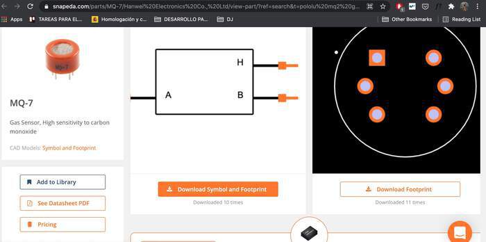
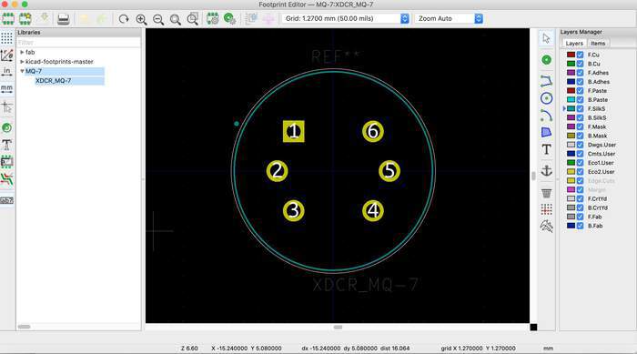
Then Henk, helped me by looking at the fooprint of MQ7 which is the same, so I downloaded it from here
-
I understand the gas sensor sends the info to the microcontroller and the microcontroller to the output pins which I have chosen to use a red led and a buzzer. The LED would turn red when there was a gas leakage and the buzzer would start beeping.
-
Now my question was what microcontroller did I have to use? Henk told me that if I knew the code I was going to use I could compile it and see the size of it to know which microcontroller to use. “Before you can upload your program to your microcontroller, you need to compile it. This means converting the code from human-readable code to machine-readable code.” Source So I looked into different code examples; example 1 and example 2
-
I copied both codes into code type 1 and code type 2 and saved them. When opening the files it saw they were 809 bytes.
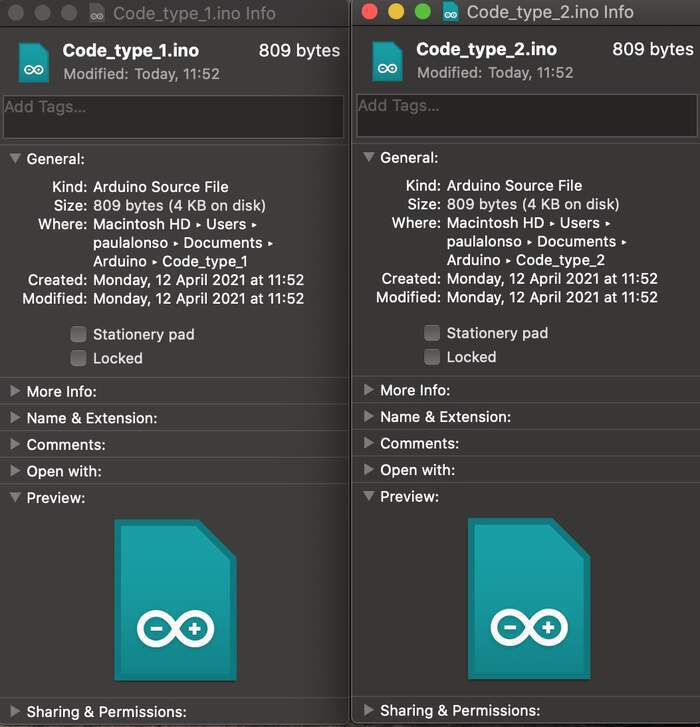
-
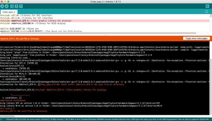
I then realised this was not the compiling, the compiling information appears when compiling at the bottom of the Arduino IDE software. But this was only shown when there were no errors in the file and this code had libraries which for a OLED display which I did not need. I tried to look for a code which is connected to a microcontroller not to Arduino (the last code had libraries I did not need) but I could not find any. FINALLY I found the solution (Henk helped me a lot).
-
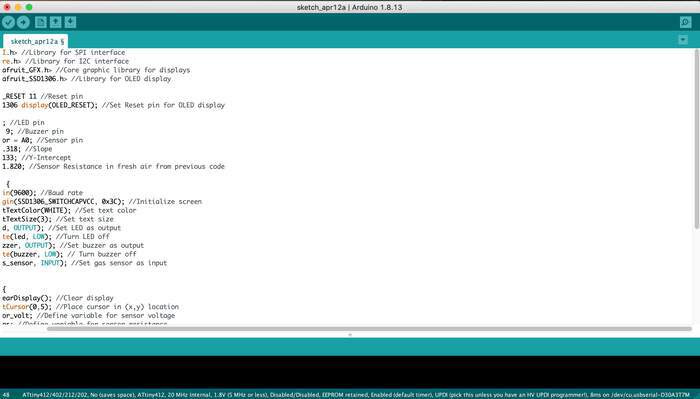
Basically I knew this code would kind of work because it had the same components I wanted for my board: LED light, buzzer, and gas sensor.
#include <SPI.h> //Library for SPI interface
#include <Wire.h> //Library for I2C interface
#include <Adafruit_GFX.h> //Core graphic library for displays
#include <Adafruit_SSD1306.h> //Library for OLED display

#define OLED_RESET 11 //Reset pin
Adafruit_SSD1306 display(OLED_RESET); //Set Reset pin for OLED display

int led = 10; //LED pin
int buzzer = 9; //Buzzer pin
int gas_sensor = A0; //Sensor pin
float m = -0.318; //Slope
float b = 1.133; //Y-Intercept
float R0 = 11.820; //Sensor Resistance in fresh air from previous code

void setup() {
  Serial.begin(9600); //Baud rate
  display.begin(SSD1306_SWITCHCAPVCC, 0x3C); //Initialize screen
  display.setTextColor(WHITE); //Set text color
  display.setTextSize(3); //Set text size
  pinMode(led, OUTPUT); //Set LED as output
  digitalWrite(led, LOW); //Turn LED off
  pinMode(buzzer, OUTPUT); //Set buzzer as output
  digitalWrite(buzzer, LOW); // Turn buzzer off
  pinMode(gas_sensor, INPUT); //Set gas sensor as input
}

void loop() {
  display.clearDisplay(); //Clear display
  display.setCursor(0,5); //Place cursor in (x,y) location
  float sensor_volt; //Define variable for sensor voltage
  float RS_gas; //Define variable for sensor resistance
  float ratio; //Define variable for ratio
  float sensorValue = analogRead(gas_sensor); //Read analog values of sensor
  sensor_volt = sensorValue*(5.0/1023.0); //Convert analog values to voltage
  RS_gas = ((5.0*10.0)/sensor_volt)-10.0; //Get value of RS in a gas
  ratio = RS_gas/R0;  // Get ratio RS_gas/RS_air

  double ppm_log = (log10(ratio)-b)/m; //Get ppm value in linear scale according to the the ratio value
  double ppm = pow(10, ppm_log); //Convert ppm value to log scale
  double percentage = ppm/10000; //Convert to percentage
  display.print(percentage); //Load screen buffer with percentage value
  display.print("%"); //Load screen buffer with "%"
  display.display(); //Flush characters to screen

  if(ppm>2000){ //Check if ppm value is greater than 2000
    digitalWrite(led, HIGH); //Turn LED on
   digitalWrite(buzzer, HIGH); //Turn buzzer on  }  else{ //Case ppm is not greater than 2000    digitalWrite(led, LOW); //Turn LED off    digitalWrite(buzzer, LOW); //Turn buzzer off  }   }
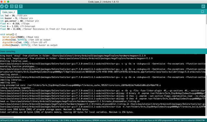
- The problem was that it used a OLED DISPLAY: which I did not need. (trying to work in spirals). Together with Henk we deleted the code which was related with the OLED (mostly display;), sorted out the curly brackets and wala! compiles. I modified the code from this source
int led = 10; //LED pin
int buzzer = 9; //Buzzer pin
int gas_sensor = A0; //Sensor pin
float m = -0.318; //Slope
float b = 1.133; //Y-Intercept
float R0 = 11.820; //Sensor Resistance in fresh air from previous code

void setup() {
  Serial.begin(9600); //Baud rate
  pinMode(led, OUTPUT); //Set LED as output
  digitalWrite(led, LOW); //Turn LED off
  pinMode(buzzer, OUTPUT); //Set buzzer as output
  digitalWrite(buzzer, LOW); // Turn buzzer off
  pinMode(gas_sensor, INPUT); //Set gas sensor as input
}

void loop() {
  float sensor_volt; //Define variable for sensor voltage
  float RS_gas; //Define variable for sensor resistance
  float ratio; //Define variable for ratio
  float sensorValue = analogRead(gas_sensor); //Read analog values of sensor
  sensor_volt = sensorValue*(5.0/1023.0); //Convert analog values to voltage
  RS_gas = ((5.0*10.0)/sensor_volt)-10.0; //Get value of RS in a gas
  ratio = RS_gas/R0;  // Get ratio RS_gas/RS_air

  double ppm_log = (log10(ratio)-b)/m; //Get ppm value in linear scale according to the the ratio value
  double ppm = pow(10, ppm_log); //Convert ppm value to log scale
  double percentage = ppm/10000; //Convert to percentage


  if(ppm>2000){ //Check if ppm value is greater than 2000
    digitalWrite(led, HIGH); //Turn LED on
    digitalWrite(buzzer, HIGH); //Turn buzzer on
   }  else { //Case ppm is not greater than 2000
    digitalWrite(led, LOW); //Turn LED off
    digitalWrite(buzzer, LOW); //Turn buzzer off
    }
   }
-
This is what appeared when compiling:
-
From this I learned that with the memory used I could use a ATtiny 412, (the buzzer and the LED dont consume memory), just the program which is loaded. Which is good because I had already worked with this microcontroller for my helloechoboard.
-
This was the component list I had so far:
| Component | Information | Orientation |
|---|---|---|
| ATtiny 412 | Microcontroller_ATtiny412_SSFR | Yes |
| UPDI header | Conn_UPDI_01x02_Male | Yes |
| FTDI header | Conn_FTDI_01x06_Male | Yes |
| Capacitor 1uF | C_1206 | No |
| Red LED | LED_1206/160-1167-1-ND | Yes |
| Resistor 1 | 5k for the LED | No |
| Gas Sensor | MQ-2 | Yes |
| Resistor 2 | For the gas sensor Adjustable resistance(I have to calculate it)I will start with a 10k resistor | No |
| Buzzer | ? | ? |
** Nadieh explained me the capacitor we used in the Hello Echo Board was used for the microcontroller to reduce noise (you would generally want one next to all kind of microcontrollers) it also works when something goes wrong with the ftdi connection it will kind of boost current to the IC. So I did need this in my new board.
-
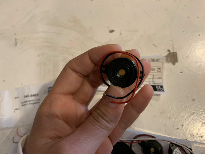
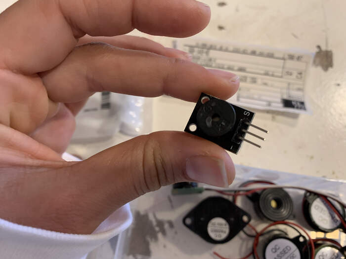
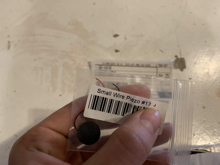
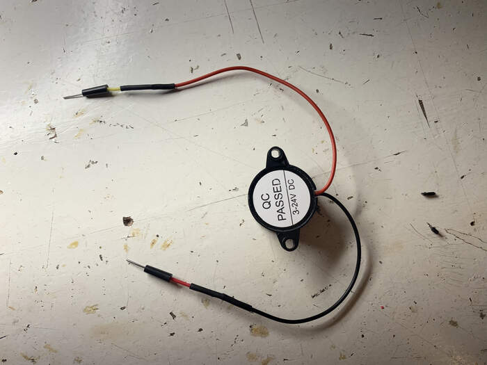
Choosing a buzzer: I asked Henk if he had buzzer in the lab and he showed me all these options:
-
So I looked them all up in Digikey to see which one would suit me best. I was doubting of the intensity of the noise but in this video it shows a small buzzer and it sounds quite intense. Then I found this video about Piezo Buzzer comparation which measures the output sound of various buzzers.
-
I learned what rating voltage means from this source “The voltage rating is not the maximum at which breakdown occurs, it is a percentage of the maximum and is intended to be a safe level for extended use.” From Quora I also found this explanation: “Rated as in rated voltage means the voltage at which the circuit or motor or component is designed to work with. For example, if you want to make/design a circuit for a particular application, then according to that you have to decide which component to use and which supply voltage to use. This supply voltage that you decided to use becomes the rated voltage when the circuit is complete.Rated current means the value of the current that the circuit is using at its full load. If on a motor name plate it is written that the rated current is 10A, it simply means that it consumes 10A current for whichever the load it works on. The load at which it consumes the 10A is called full load. The motor can easily accommodate current below 10A. But working at above this load is not safe. Leads to heating of the winding and subsequent damage to the machine.”
-
Other type of buzzer with good reviews How to use a Buzzer? “A buzzer is a small yet efficient component to add sound features to our project/system. It is very small and compact 2-pin structure hence can be easily used on breadboard, Perf Board and even on PCBs which makes this a widely used component in most electronic applications.” There are two types are buzzers that are commonly available. The one shown here is a simple buzzer which when powered will make a Continuous Beeeeeeppp.... sound, the other type is called a readymade buzzer which will look bulkier than this and will produce a Beep. Beep. Beep. Sound due to the internal oscillating circuit present inside it. But, the one shown here is most widely used because it can be customised with help of other circuits to fit easily in our application. This buzzer can be used by simply powering it using a DC power supply ranging from 4V to 9V. A simple 9V battery can also be used, but it is recommended to use a regulated +5V or +6V DC supply. The buzzer is normally associated with a switching circuit to turn ON or turn OFF the buzzer at required time and require interval. The datasheet from this buzzer.
-
Choosing a resistor: From this source I learned I could choose different types of resistors: “Besides the built in resistor, it is necessary to include a load resistor. This resistor serves to adjust the sensor’s sensitivity and accuracy. The value can range anywhere from 2k Ohms to 47k Ohms. The higher the value, the more sensitive the sensor becomes. The value depends on whether you want to measure high concentrations of gas or not. If you choose to measure high concentrations of gas, but choose a high value for the load resistor, then the readings won’t be very accurate. Lastly, there is another built-in resistor used for the heater of the sensor. The heater is used to provide the temperature that the sensor needs to work properly. In the end, we have a circuit like this:”
-
Once I have more a less my schematic I know I need a Gas Sensor footprint, which I will get from the link Henk sent me and a buzzer footprint which I also do not have.
-
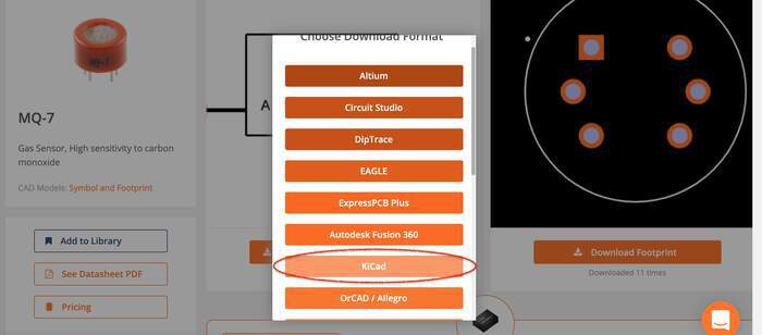
So for this I downloaded the Gas Sensor footprint, you have to create an account previously:
-
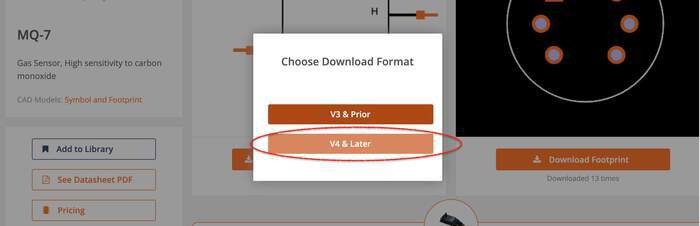
As I have version 5 I downloaded v4 or later version:
-
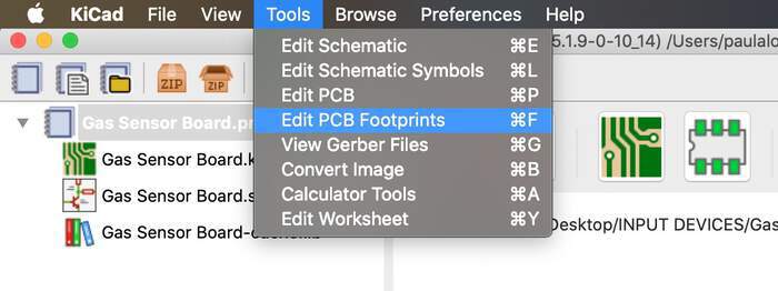
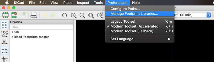
To import the files into the Ki-CAd library I followed these steps
In KiCad, go to Tools > Edit PCB Footprints.
Click on Preferences > Manage Footprint Libraries.
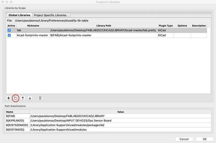
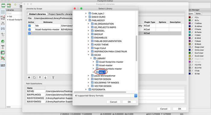
In the Global Libraries tab, click on Add existing library to table, the small folder icon and navigate to the downloaded folder where your .kicad_mod file is located. Then click OK.
Use the search bar on the left pane of the window to search for the imported footprint and double-click it to open.
-
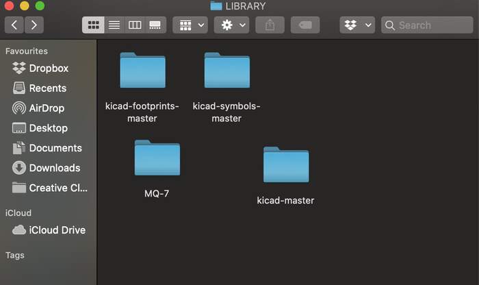
I moved the MQ-7 folder to the library in kicad
-
I then followed the steps.
-
Done:
-
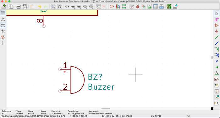
The buzzer I chose does not need a footprint because it is not soldered to the board, so I will connect it to the board with jumper wires, I just need to put a 2 pin header, one connected to ground and one connected to the pin of microcontroller which will make the beep sound when the gas concentration is too high. When choosing the 2 pin header I had 2 options: the difference is that one is laying flat (UPDI) and the other one the pins are going upwards. I will use the same connection as the UPDI.
-
I now have all my symbols + footprints.
-
I will annotate my components:
-
Remember the shortcuts:
M (press M in keyboard and a component with mouse to move component around)

R (press R in keyboard and a component with mouse to rotate component)

C (press C in keyboard and a component with mouse to copy component)

E (press E in keyboard and a component with mouse to assign a value to a component in text box)
-
I also added extra values for the capacitor(1upF), LED resistor (5k), gas sensor resistor (?I am not sure of this), and the name of MQ-2 gas sensor. I also added VCC and GND which I had forgot about.
-
What resistor to use with the gas sensor? Because I dont really know how to calculate the resistance needed Henk recommended to put in my board a 2 pin female header where I can pin different resistors in, to test different resistances which actually made more sense because it was what I was thinking to do but with soldering and reflowing (not very practical). Because there is no footprint for the female 2 pin I will be using a UPDI.
-
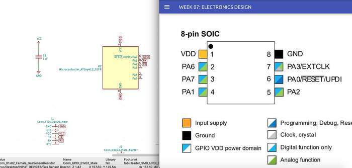
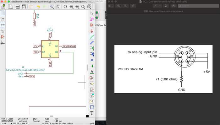
I connect with green wires the simple connections and now it is time to make the labels: For the microcontroller: I know 1 is VCC, 2 is GND, 6 is connected to UPDI, 2, 3, 4, 5 for digital and analog functions, 7 is for digital, analog functions and also for clock/ crystal:
-
I assume for the FTDI I don’t need the CTS or RTS.
-
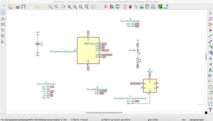
This would be my finished schematic:
-
I also placed the power flag ports for VCC and GND to avoid the errors from last time. The errors that appeared was:
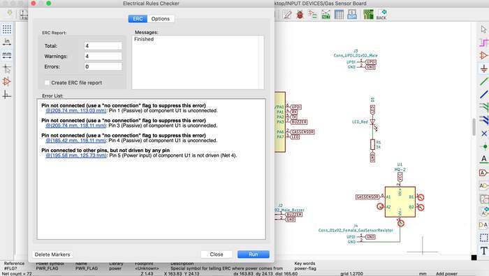
-
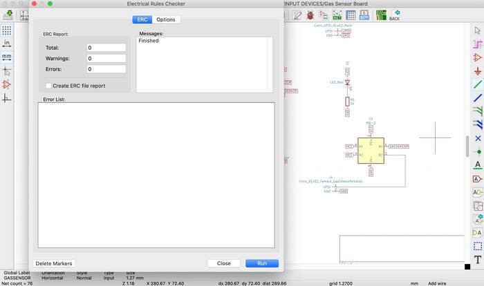
I reopened one of the pin explanation from the datasheet and compared them. After this I realised I did not need the no connection flags but rather connect them to VCC and also the resistor was not correctly connected. I did this with the pinout image. I runned the PCB checker again and no errors appeared.
-
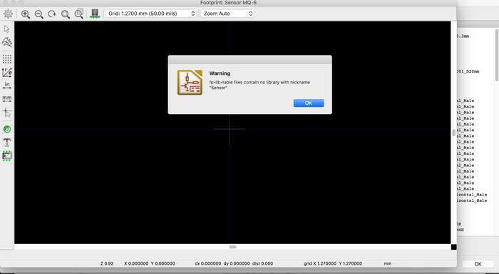
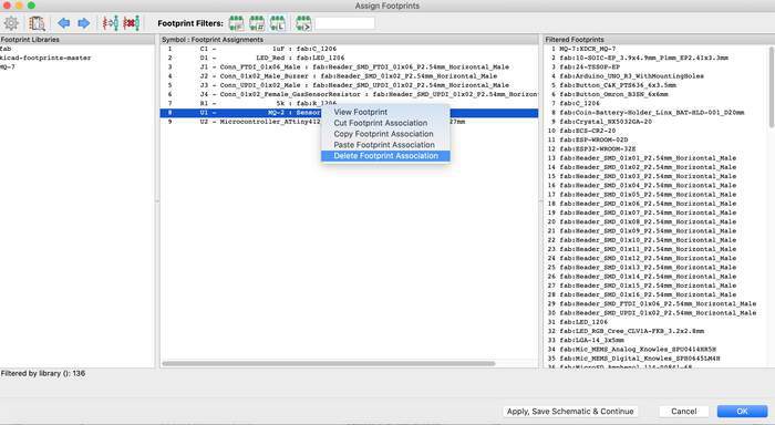
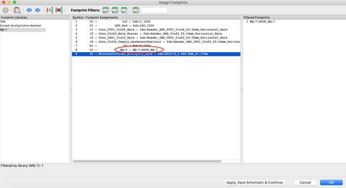
Assign PCB footprints button. When I checked that all the sensors were there the only one that was missing was the MQ-2 sensor. As I had just add it I saved and closed the software and reopened it. The same happened, then I realised it was because the symbol was different than the footprint and I had to assign this one to it. Right click on the sensor > Delete Footprint association. Then I chose the new footprint > Apply, Save schematic and continue. Done!
-
I save the schematic and open the PCB editor.
-
What I learned when making the schematic was that creating circuits is like a puzzle, you figure out one component(piece) and then you figure out the component(piece) connected to it, and so on till you complete your circuit. It was fun!
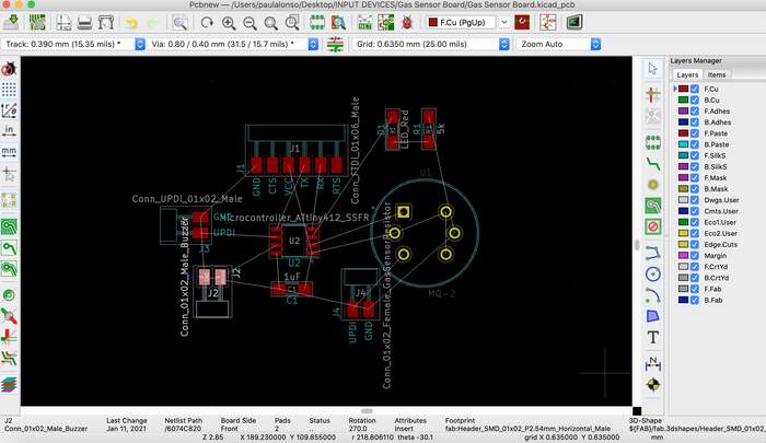
Designing board
-
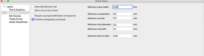
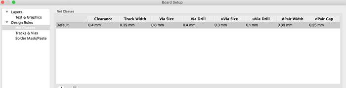
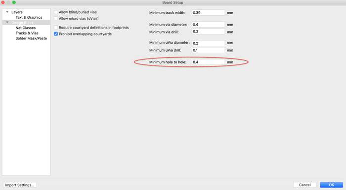
Once in the PCB editor I open the design rules and changed them as we did in the electronics production week.
-
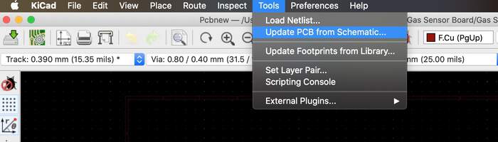
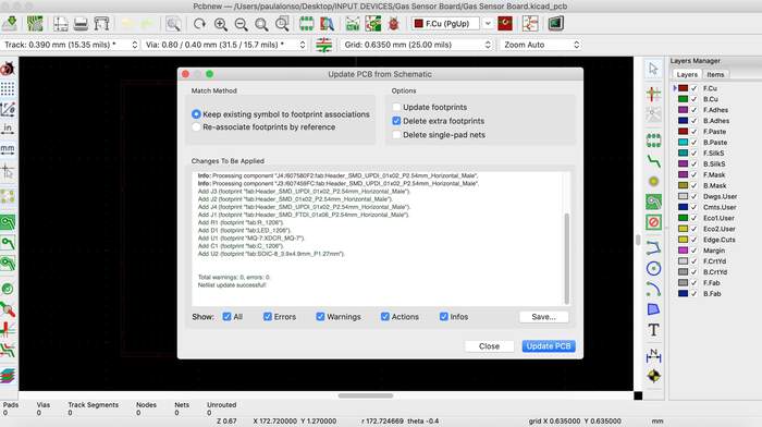
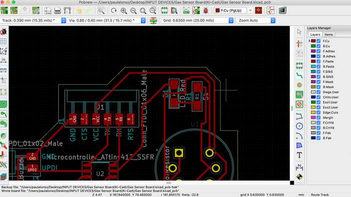
Tools > Update from schematic
-
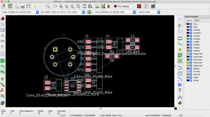
The initial mess of components, I realise the Gas sensor footprint already looks too big but I doubled checked with Henk and he said it is this big in real life.
-
I run over the documentation tips from Tessel, especially because in the embedded programming week I messed it up a lot with the soldering/ traces design:
| Tips | Done |
|---|---|
| Make sure traces do not overlap. | Done |
| You can run a trace under the resistor. | Not needed |
| Timing: even the smallest trace of copper takes time. Place the resonator and the resistor as close as possible to the chip and make sure the two traces are the same length. | Done |
| The capacitor has to be as closest as possible to the microcontroller | Done |
| Traces have to be at least 0.4mm distance. How do we measure in Kicad to know they are so far apart? | Done |
-
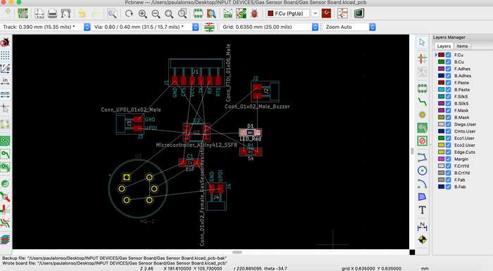
For the orientation I positioned it similar to the hello echo world as last time it took me decades to find out a configuration. I also remembered Loes’s tip: “For tracing: start with the important things, then the VCC and only last the GND”. I also realised you could measure traces with the N symbol in the right hand menu, found the solution here.
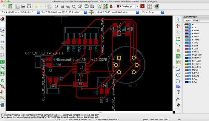
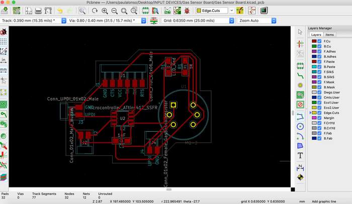
-
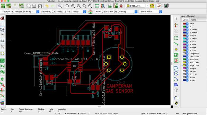
Ran the PCB checker, no errors. I drew the outline line, I also made sure there was not so much copper space wasted. With the outline.
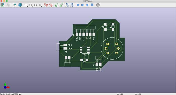
-
Opened 3D viewer, everything looked fine:
-
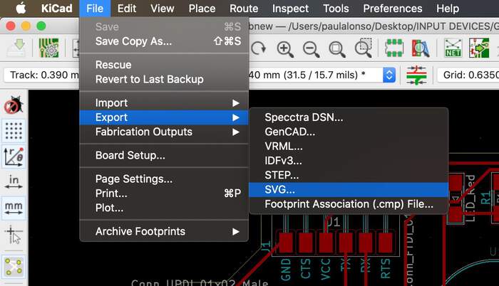
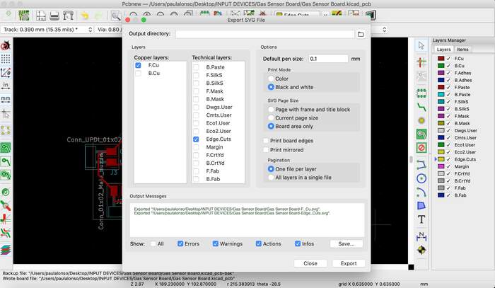
Everything looked fine so I exported the file as an SVG:
Milling board
-
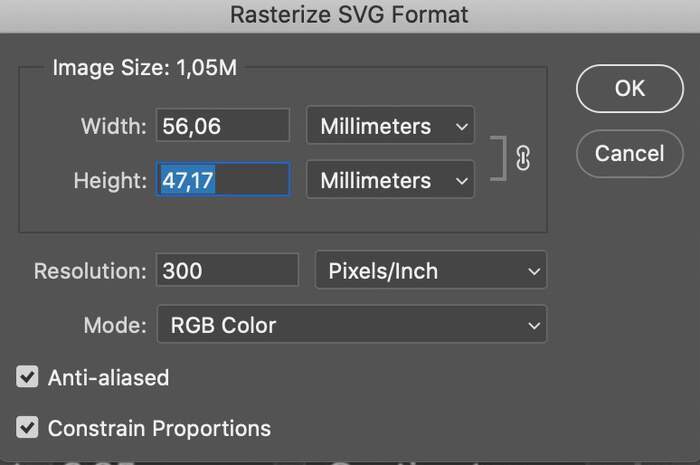
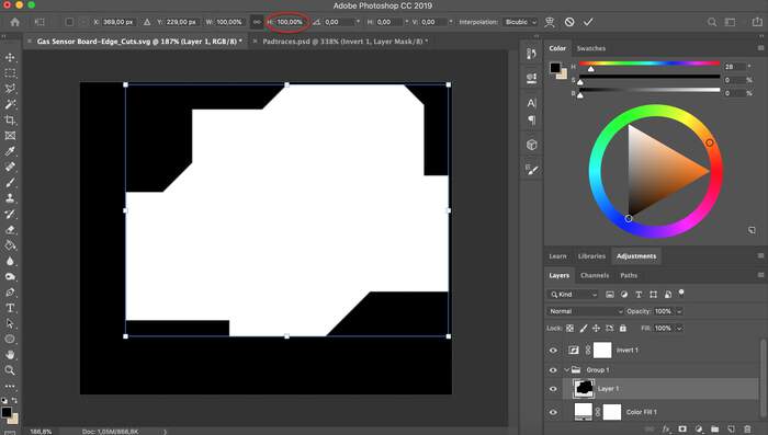
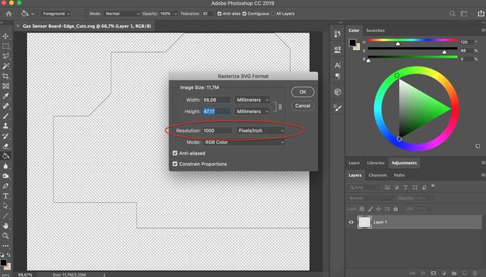
I did all the steps in Photoshop from my Electronics Design week which were open the file in mm + resolution (I then learned the resolution has to be 1000), then I had to create a new solid color layer, put it underneath my file and then invert them both.
-
I also had to scale the outline trace like last time.
-
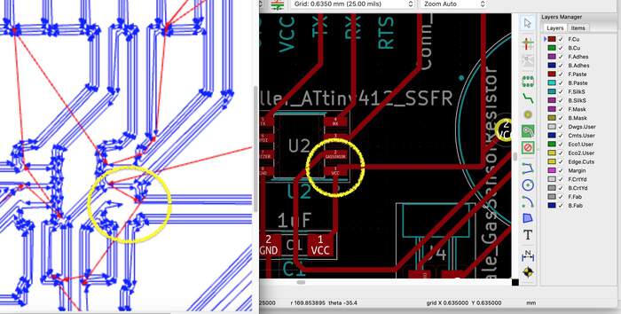
When I opened this the traces did not appear right in MODS:
-
I disocvered this was an HTML problem because when I opened it in safari mods it was okay.
-
I also saw there was a pad from the chip that was not traced in the 3Dviewer so I went back to KiCad and changed the trace to it by centering it more and not putting it so close to the pad edge. This worked out.
-
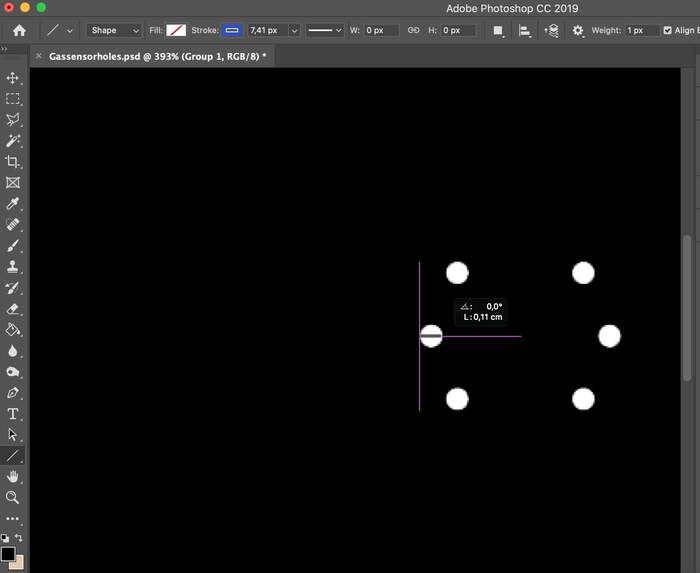
Henk showed me the MQ-4 and told me how I would have to solder it which meant I had to make an extra file to cut the holes so that the sensor would hold more sturdy to the board, I would cut this first:

-
I measured the holes to check if I could mill the holes with the 0.8 endmill and I could:
-
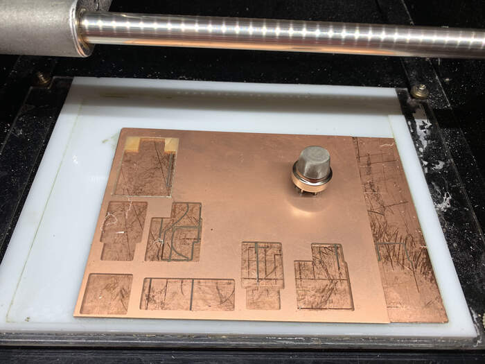
When milling the holes we realised they were too big, this was because I had milled the outside path. To avoid this I would have had to invert the image:
-
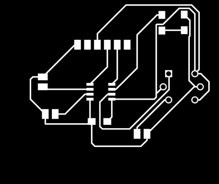
My other files looked like this:

-
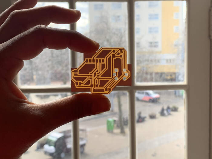
Final board looked like this:
Soldering board
- Before soldering I doubled checked which component needed orientation:
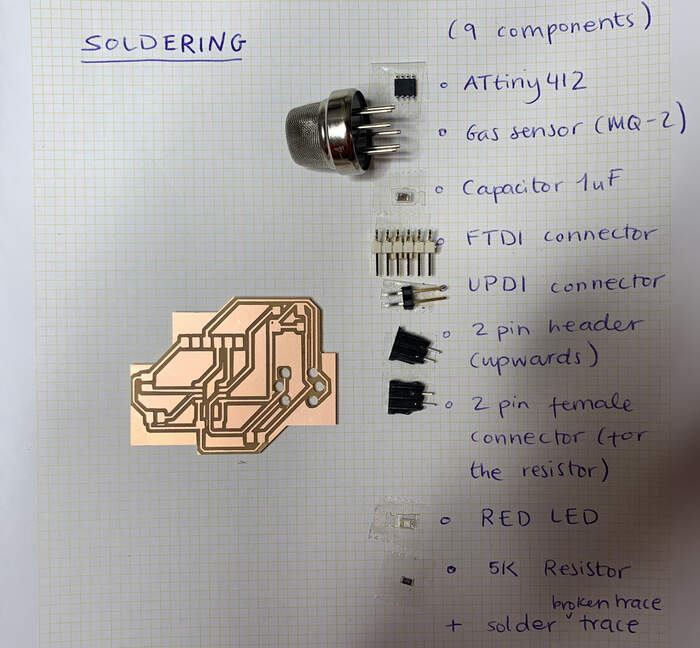
| Component | Information | Orientation |
|---|---|---|
| ATtiny 412 | Microcontroller_ATtiny412_SSFR | Yes |
| UPDI header | Conn_UPDI_01x02_Male | Yes |
| FTDI header | Conn_FTDI_01x06_Male | Yes |
| Capacitor 1uF | C_1206 | No |
| Red LED | LED_1206/160-1167-1-ND | Yes |
| Resistor 1 | 5k for the LED | No |
| Gas Sensor | MQ-2 | Yes |
| Resistor 2 | ? | No |
| Buzzer | ? | Yes |
-
Although the holes were too big, I decided to solder anyway as I though there could be an option afterwards. The MQ-2 was arriving on Wednesday (the next day) so I still had time to decide other ways of soldering it to the board.
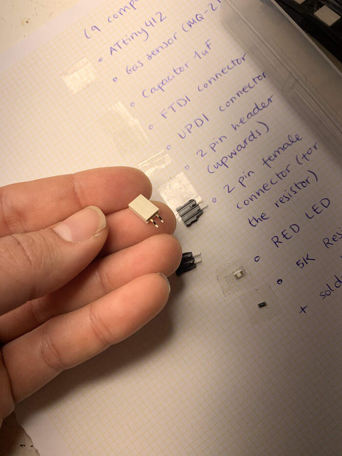
-
I confused the pin as I was getting the wrong ones and I had to use the same one as the UPDI for the resistor and the buzzer:
-
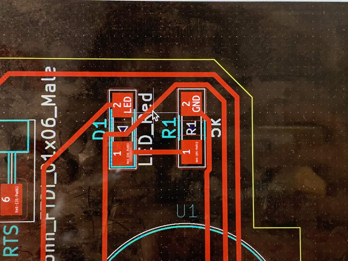
There were some traces and pads that were joined together where they should not:
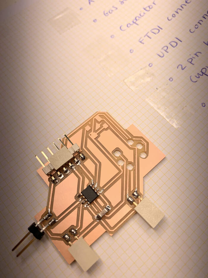
-
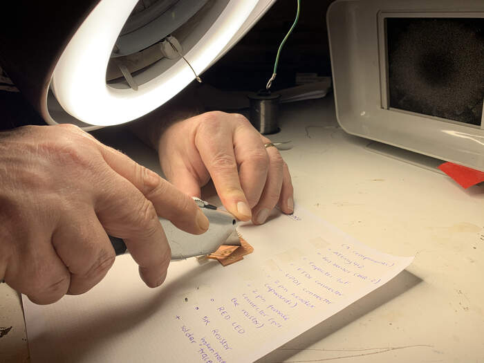
We fixed this by separating them with a knife:
-
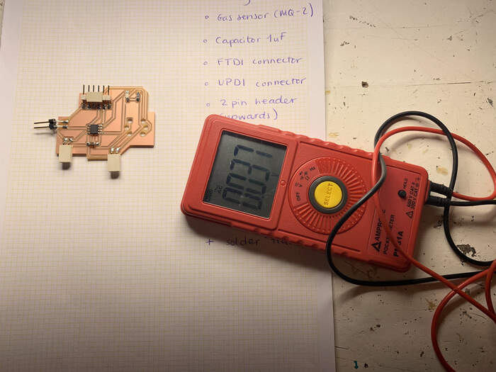
The soldering went fine, one useful trick was to use the multimeter everytime I soldered a component to check whether the traces that had to be connected were connected but also to check whether the ones that did not have to be connected weren’t connected:
-
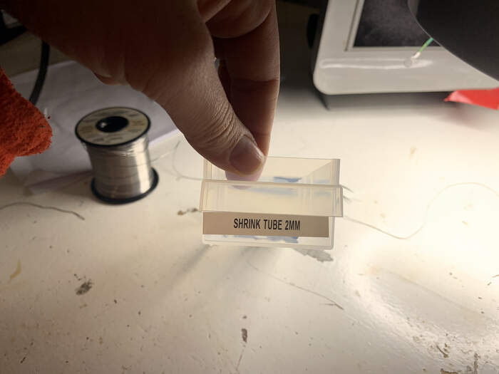
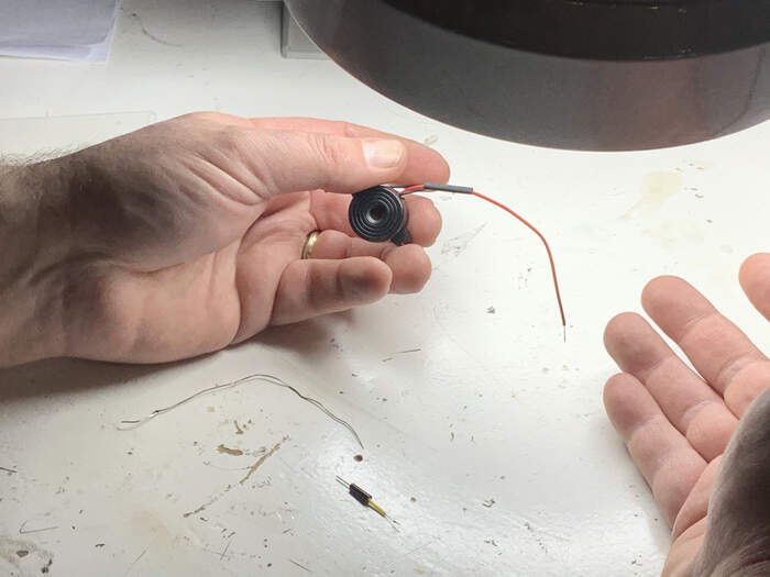
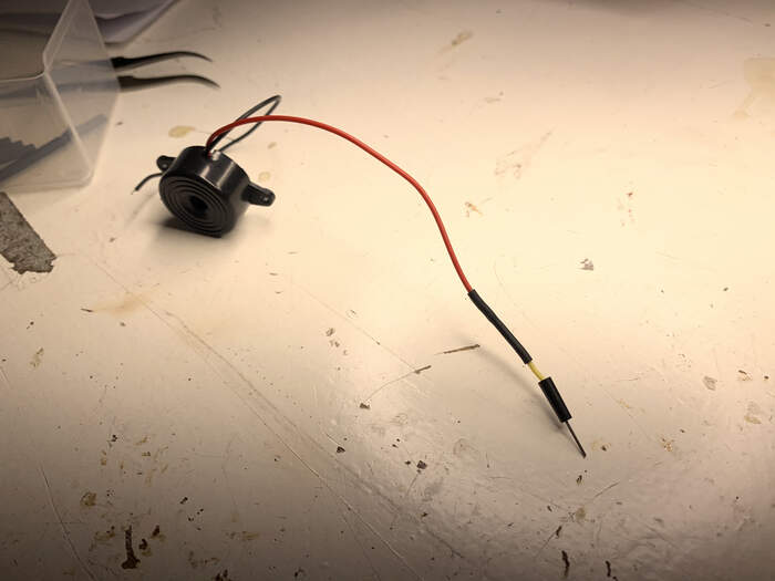
For the buzzer Henk showed me how to solder the wires from the buzzer to some cut jumper wire which would fix better to the UPDI connection. For this we soldered both wires and protected the soldering with a shrinking tube which when you heat it up it shrinks. This was a very cool technique!
-
First you have the buzzer wire with the shrinking tube already through:
-
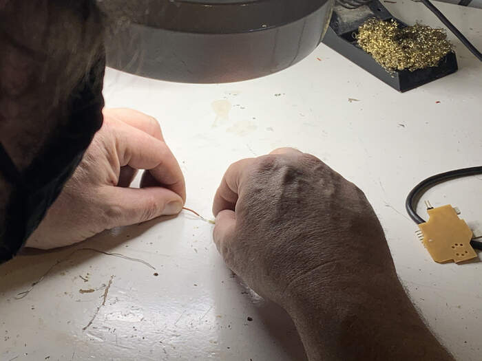
Second you put some solder on the buzzer wire and then you put separately some solder on the jumper wire(you cut the top part with the pin)
-
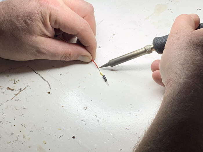
Third you put one wire on top of the other and you solder them both:
-
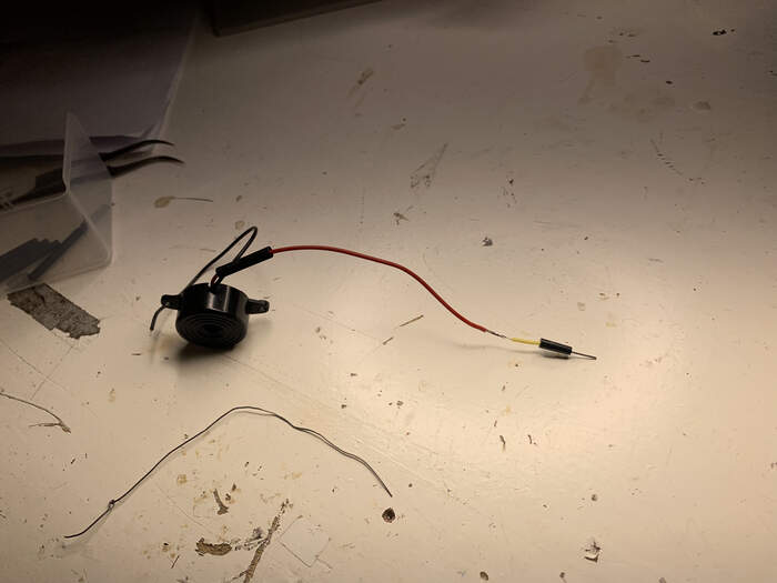
After this step you place the shrinking tube on the joined pieces and with the hot gun you softly make it fall in place (this takes about 2 seconds):
-
Henk showed me how to do one and I did the other one:
-
Everything soldered except the gas sensor:
Second time milling
-
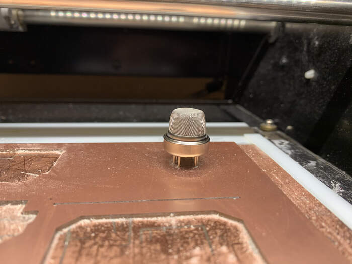
On Wednesday, we tried different ways of trying to solder the sensor but we realised the holes were way too big and the easiest way to fix this would be to mill another board and solder it. When doing this I had to invert the image, so the holes had to be black, this would make the milling be on the inside and not on the outside path.

-
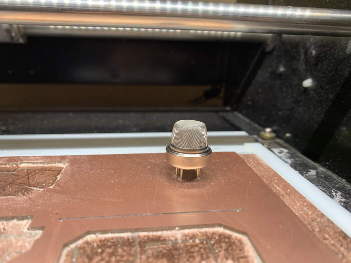
I milled it first and the gas sensor fits way better this time.
-
I also fixed the traces and pad that were too close by modifying this design rule:
-
And also by separating the traces to the component:
-
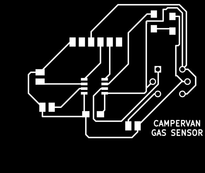
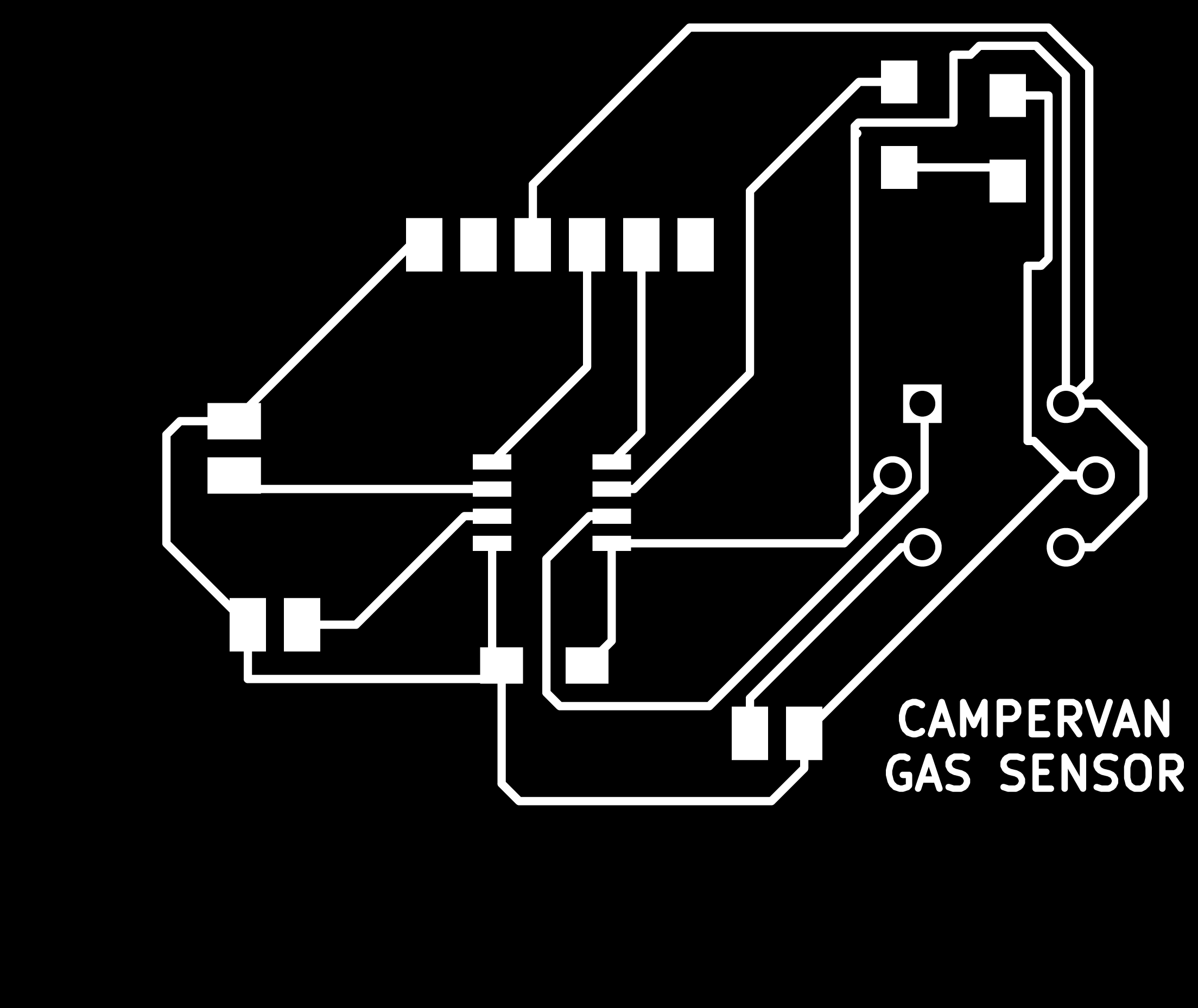
I also added text to my board:
-
In Photoshop I also learned we have to put the resolution to 1000!!!
-
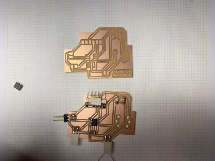
These were the final png’s:

-
I milled everything fine, these were the new holes for the sensor:
-
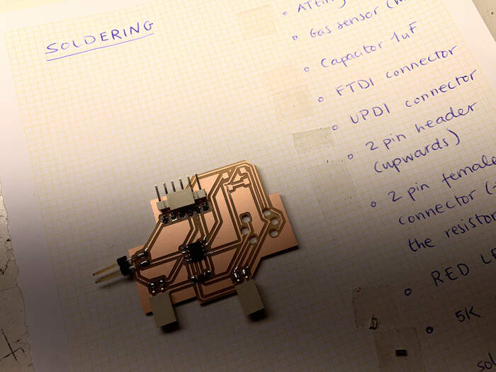
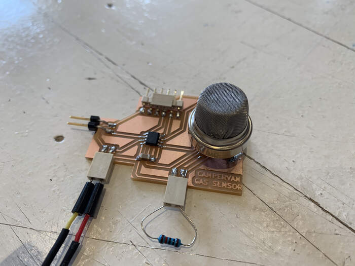
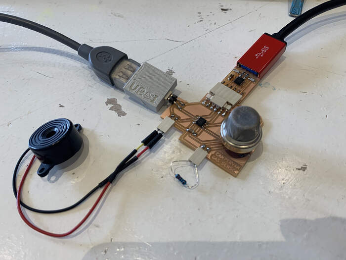
This was the final board:

-
I then soldered all the components again. I found out the gas sensor had no orientation, so you could solder it both ways.
Writing code for the board and sensor
-
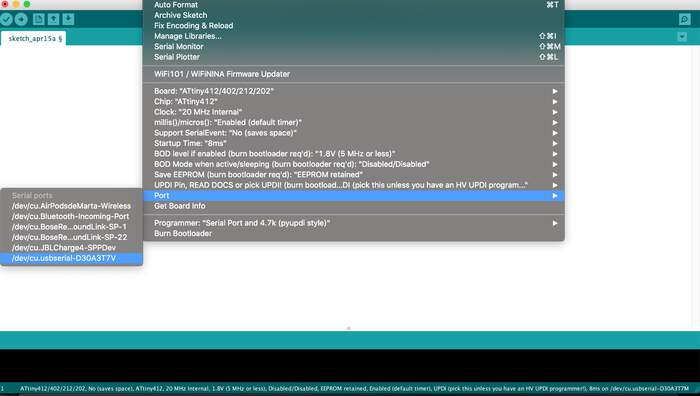
I still have to find out a way of testing my gas sensor but for the moment I tried testing if the LED and the buzzer worked. I connected the UPDI:
-
First I set up the Arduino IDE:
-
What I did was to use a code from Nadieh which I had already used in my embedded programming week and I knew it worked. I used the following code:
// Blink the LED on and off every two seconds

#define led_pin PIN_PA6 // This uses the ATtiny pin number
//const int led_pin = 0; // This uses the Arduino pin number instead

// The setup function only runs once when you press reset or power the board
void setup() {
  // Use the alternate pin positions due to swapped TX&RX pins
  Serial.swap(1);
  // Initialize digital pin led_pin as an output
  pinMode(led_pin, OUTPUT);
}

// The loop function runs over and over again forever
void loop() {
  digitalWrite(led_pin, HIGH);   // Turn the LED on (HIGH is the voltage level)
  delay(1000);                   // Wait for a second (= 1000 microseconds)
  digitalWrite(led_pin, LOW);    // Turn the LED off by making the voltage LOW
  delay(1000);                   // Wait for a second
}
- I defined the LED pin and the LED started blinking:
- After this I used the same code for the buzzer I just defined its pin:
// Blink the LED on and off every two seconds

#define BUZZER_pin PIN_PA3 // This uses the ATtiny pin number
//const int led_pin = 0; // This uses the Arduino pin number instead

// The setup function only runs once when you press reset or power the board
void setup() {
  // Use the alternate pin positions due to swapped TX&RX pins
  Serial.swap(1);
  // Initialize digital pin led_pin as an output
  pinMode(led_pin, OUTPUT);
}

// The loop function runs over and over again forever
void loop() {
  digitalWrite(led_pin, HIGH);   // Turn the LED on (HIGH is the voltage level)
  delay(1000);                   // Wait for a second (= 1000 microseconds)
  digitalWrite(led_pin, LOW);    // Turn the LED off by making the voltage LOW
  delay(1000);                   // Wait for a second
}
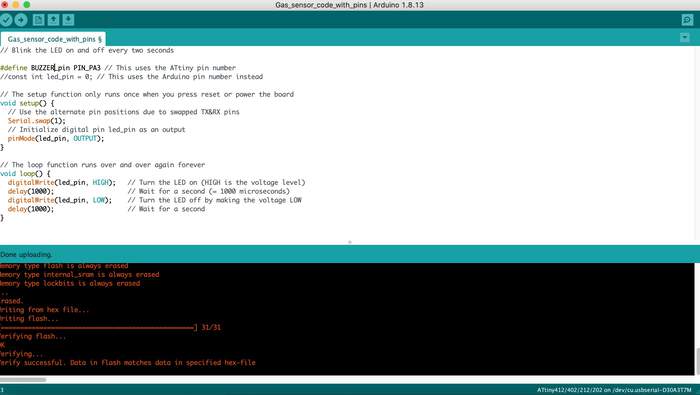
- This is the result from the buzzer:
-
I worked out that the buzzer was sounding too low (I had to adjust the current or change the buzzer as it has 3-24V).
-
The next step is to find ways to test the gas sensor.
-
I also have to test a new buzzer.
I learned how to read the gas sensor values on the Interface and application programming you can see this part of the documentation there.
Files to this week’s assignments:
-
This is the Ki-CAD schematic file in PDF | kicadsch
-
This is the Gas sensor holes PNG | gassensorholespng
-
This is the Traces PNG | tracespng
-
This is the Interior PNG | interiorpng