Week 07: Computer-controlled machining
Assignments:
-
Group assignment: Test runout, alignment, speeds, feeds, and toolpaths for your machine. Document your work (in a group or individually)
-
Individual assignment: Make (design+mill+assemble) something big
What to learn:
-
Demonstrate 2D design development for CNC production
-
Describe workflows for CNC production
Have you?
-
Linked to the group assignment page
-
Documented how you designed your object (something big)
-
Documented how you made your CAM-toolpath
-
Documented how you made something BIG (setting up the machine, using fixings, testing joints, adjusting feeds and speeds, depth of cut etc.)
-
Described problems and how you fixed them
-
Included your design files and ‘hero shot’ photos of final object
DOUBT: How big is big? Answer: Life size, big enough to show you understand many of the possibilities of CNC machining - drill, pocket, dogbones, nesting, etc.
DOUBT: Does it have to be wood or wood products? Answer: No. But the lab is only responsible for providing you with a full size wood board (4x8 ft).
http://academy.cba.mit.edu/classes/computer_machining/index.html
PROJECTS
These projects are a nice overview of the scope of work you can do when using a big CNC machine.
-
Opendesk grew from a design at the digital fabrication Fab lab academy.
-
Shelter 20 uses CNC manufacturing to design and fabricate shelters.
-
yOUR HOUSE is a project where they modeled a way to build a house out of parts that could be created on-site and assembled in days without nails or screws.
-
WikiHouse is a digitally-manufactured building system with an adaptable system of standardised parts. Components are manufactured by a network of local microfactories using digital fabrication tools. Homes can be rapidly assembled to millimetre precision, like a flat-pack.
-
FabHouse this is an amazing project where they developed further what WikiHouse does by designing a house which can be reproduced in the rest of fablabs in the world making it as sustainable as possible.
-
The Fab Lab House “The Fab Lab House is not simply a box with solar panels on its roof; its physical structure is integrated with its energy production and management of the information it generates. The Fab Lab House, developed with an open design, can be fabricated with local materials anywhere in the world. Its organic form, which responds directly to its environment, can be produced using advanced industrial systems which allow each dwelling to be made to measure for its users. The interior space is a multifunctional loft in which to work and rest, equipped with information technology to produce knowledge and connect to the world.”
MACHINES
-
Roland: the small milling machines we have been using to mill our electronic boards
-
Shaper: 2D cutting tool. Conventional rauder. Stands out because you don’t bring your material to the tool, but you rather bring your tool to the material.
-
ShopBot:. The one we have at Fab Lab den Waag. It is the typical CNC machine in Fab Labs
-
MTM, Machines that make The Machines That Make project at the MIT Center for Bits and Atoms is developing machines, modular machine components, end effectors, frameworks and circuits to allow rapid prototyping of rapid prototyping equipment for use in fab labs.
GROUP ASSIGNMENT: Test runout, alignment, speeds, feeds, and toolpaths for your machine. Document your work (in a group or individually)
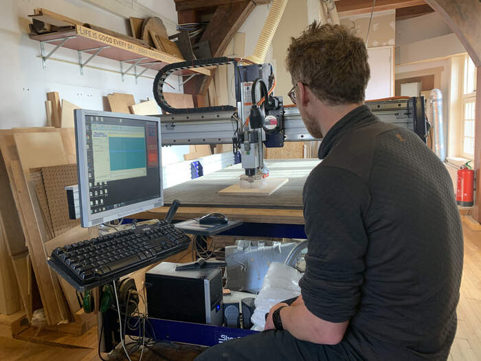
This week we were introduced to the big CNC milling machine at the lab. The machine is from the brand Shopbot as I mentioned earlier. CNC machines are electro-mechanical devices that manipulate machine shop tools using computer programming inputs. The name “CNC” actually stands for Computer Numerical Control. Basically the machine reads number codes which are interpreted as positions in space to cut with specific tools.
SAFETY INSTRUCTIONS
This is the most dangerous machine in the lab so it is important to understand the safety rules and procedures in case anything goes wrong.
-
You put on the machine when you start with the machine (not before). Only when it is needed because the machine has moving parts which can cause harm.
-
You have to master skills to work on the machine
-
Communication is vital for the machine (when working with other people)
-
One person has to sit by the computer (in order to STOP the machine if necessary) and watch out for strange things/sounds happening and the rest of the people have to be AWAY from the machine.
-
When the spindle is ON, you are not allowed to leave the room, in order to leave the room the spindle has to be out of the material.
-
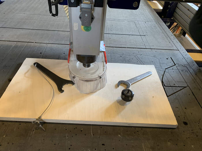
To fasten and loose the spindle there is a key(which turns ON and OFF the spindle) attached to key(which allows you to change the different milling bits from the spindle). This attachment is done so you are not able to operate the spindle while it is running.
-
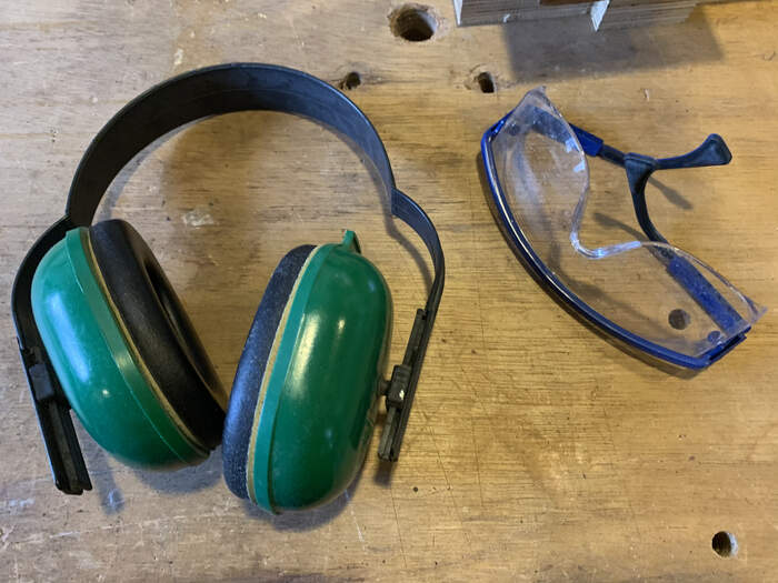
You can protect your ears but the downside is that you do not really hear everything(which is important because with the Shopbot you really hear when something goes wrong, very loud beep). You also have to wear protective glasses as chips that come off are sharp, hot and high velocity. Feet should be protected, there should not be any loose clothes and hair should be turned back. Use gloves for sharp stuff.
-
Never reach into a powered tool
-
Know HOW to stop it.
-
The biggest mistake of this machine is that people think easy for it. Take it seriously.
-
Follow EVERY step to operate the machine as it has a very precise workflow.
-
Check the working environment before starting a job, for example pieces of wood that could interfere with the movement of the machine when cutting.
-
Re-check everything. Specially cutting parameters (shopbot and v-carve software)
-
Know where the emergency exits are. In our Lab we have two fire exits.
-
Most of all, be zen and not in a hurry.
It is very easy to make fire with the machine. The common mistakes are:
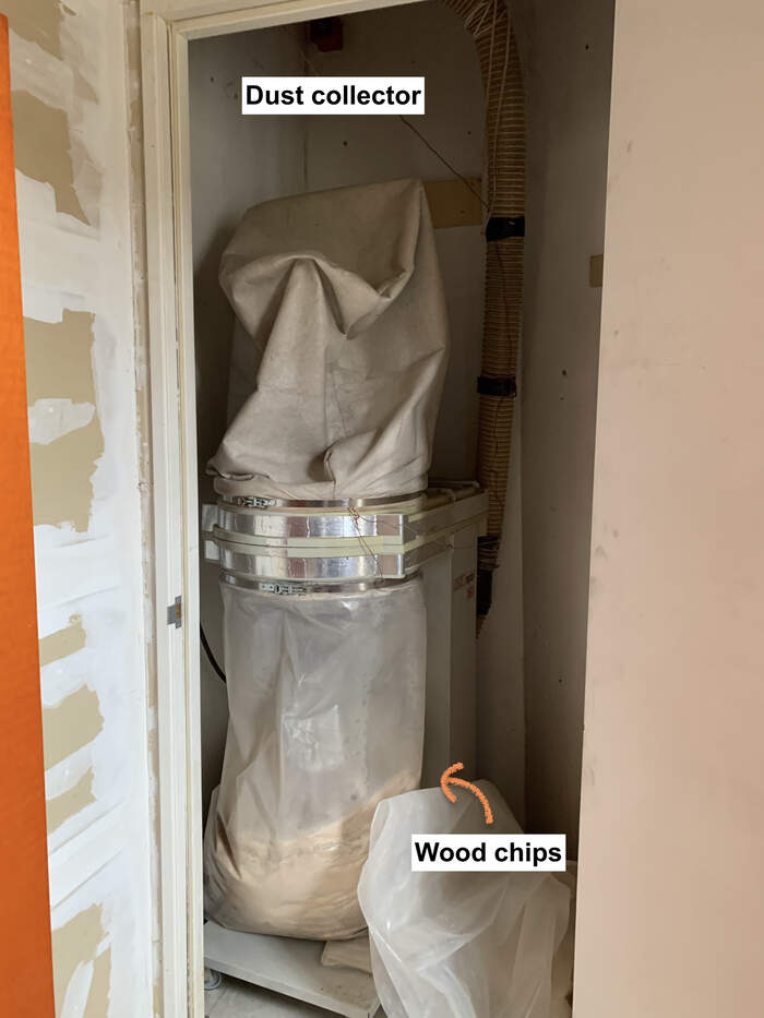
- The milling bit contacting with iron by hitting a screw(screws are used to attach the material to the sacrificial layer so that cutting is more precise). This contact will create sparks which will be extracted to the dust collector. In this case you have to quickly hit the STOP button and run to the dust collector and remove the dust collector bag from its place. If the bag has fire you have to get it out of the building as soon as possible. If there is only a bit close the bag so it prevents oxygen getting into the bag and making the fire bigger.
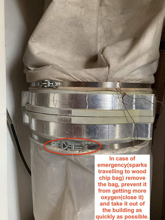
- Another common way of making fire is by the wood friction which may heat up so much that it will create fire. In this case you would do the same procedure (checking the dust collector bag if you see/ hear any anomalies)
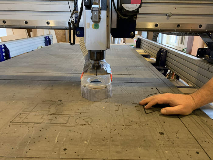
COMPONENTS OF THE MACHINE:
This is the machine we will be using:
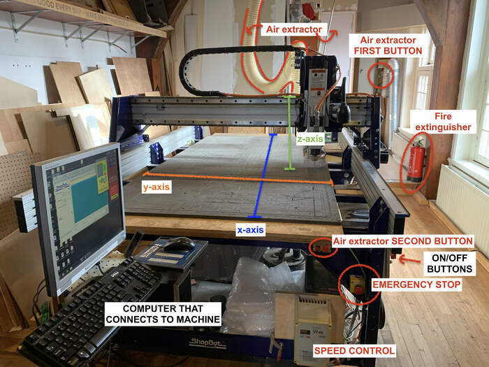
-
As you can see in the picture, the safety measures (fire extinguisher, stop emergency button, dust collector bag point, air extractors) are labeled.
-
The machine has an X, Y and Z axis. Underneath them there is a black sacrificial layer(1,22m x 2,44m) to which we will drill our boards to.
-
You can do 2D cutting and 3D cutting.
-
There is a computer communicating with the machine.
-
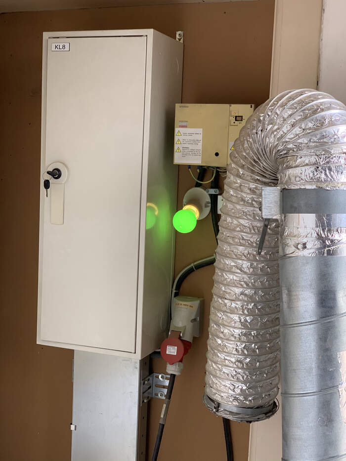
At the back of the room the air extractor(tube hanging on top of machine) takes out all the dust and wood chips to the dust collector.
-
The air extractor is first turned on at the back, this green light turns on:
-
And just about to start the job we would turn on the second air extractor which is the red button on the shopbot. The red wheel controls the amount of dust which is collected. You can regulate it yourself.
-
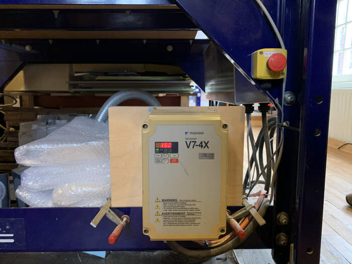
The speed of the machine is showed in this box below the Shopbot:
MACHINE WORKFLOW:
ATTACHING MILLING BIT
-
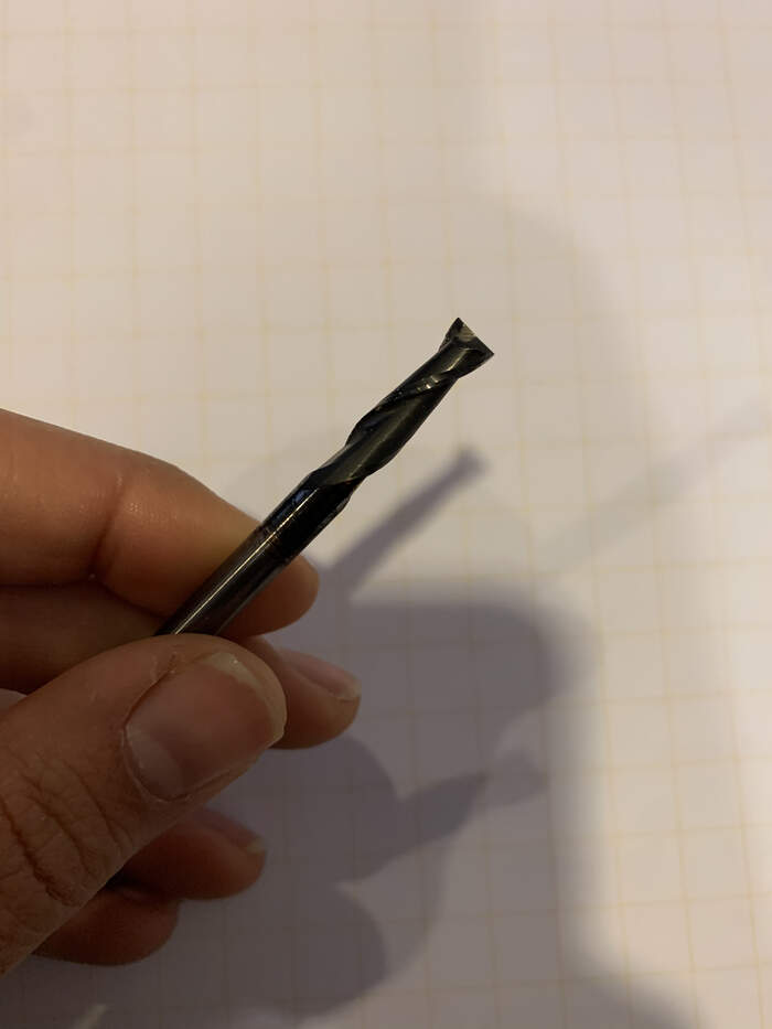
First of all we will choose a milling bit for our job. Milling bits come in different sizes and shapes and it is the tool we will use to drill our material.
-
For example, this is a 5mm(diameter) two flute endmill:
-
For example, this is a 5mm(diameter) one flute endmill:
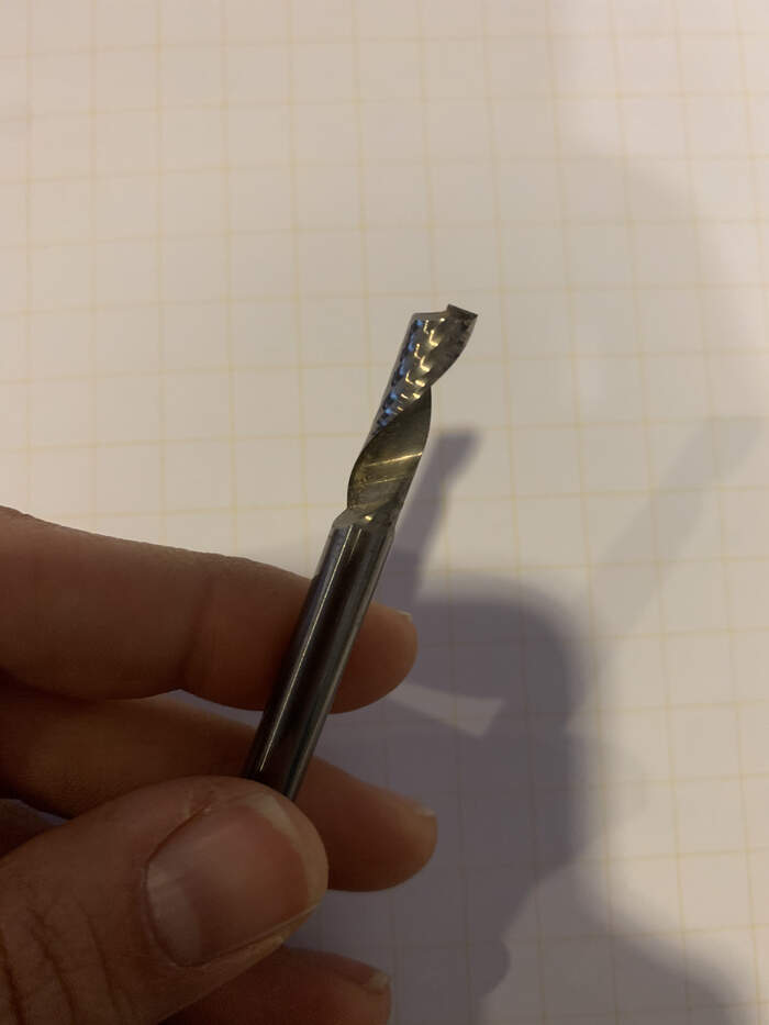
-
For example, this is a 5mm(diameter) two flute bold nose endmill:
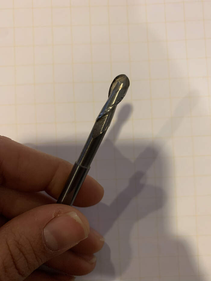
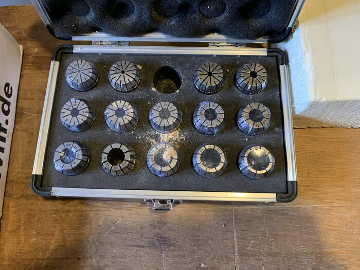
The milling bit fits in a collet and the collet fits to a nut. The order of assembling them is 1) Collet 2)Nut 3)Milling bit.
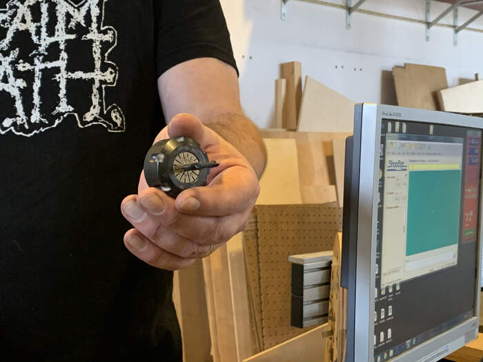
-
These three components will be attached to the spindle(in the Shopbot) which will make it move and drill. If they are not assembled correctly the machine will scream.
-
Each size of milling bit corresponds to the diameter of bit (depending on the size we want to cut) which corresponds also to the size of the collet and the size of the nut.
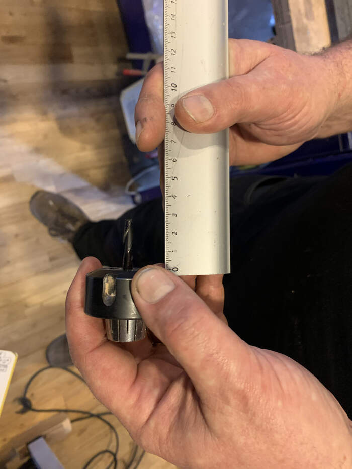
-
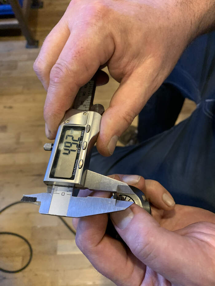
When inserting the milling bit inside the collet the milling bit has to be 2cm at least inside the collet and on the other hand you want to stick the milling bit as much as possible. If you are not sure how to check this you can always measure the whole milling bit and then measure how much sticks out.
-
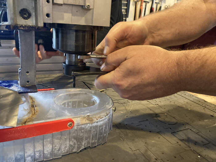
When we have the three components together we will unscrew the dust skirt, it has an unscrewing key at the back.
-
We will tighten the milling bit, nut and collid with the key attach to the chord. You have to fasten it but you also have to be able to take it out!
-
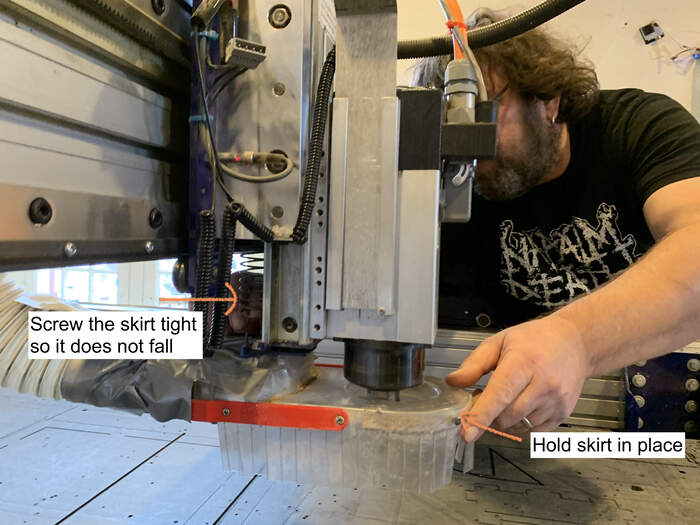
Once it is done we will put the skirt back, you will want to tighten this correctly so that the dust and chip sticks are extracted correctly and the skirt does not come down while milling or it will hurt your soft materials.
-
We will check the bed and the machine environment is totally clean (no leftover screws on sacrificial layer which can come in contact with milling bit or wooden boards sticking out which can interfere with the machine’s movement)
-
We will turn on the green button dust collector
TURNING ON MACHINE AND SETTING X, Y AND Z AXIS
-
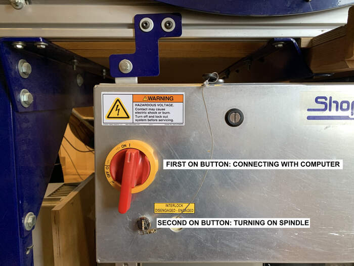
The machine has 2 ON buttons. One for allowing the machine to connect with the computer and communicate (for example set the x, y, z axis) and the second one which with you turn on the spindle (just for when you are going to start the job).
-
We turn on the first ON button to understand how to set up the X, Y, and Z axis for our group assignment.
-
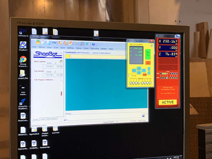
We open Shopbot, ShopBot has a lot of settings but you mostly put settings for the machine in V-Carve (Shopbot settings are left as they are).
-
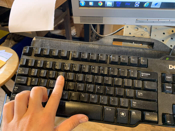
To operate the machine you press “K” on the keyboard. A yellow keypad will appear with arrows which will enable you to move the machine on the X, Y and Z axis.
-
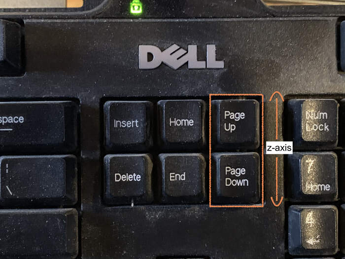
You can also use the arrows on the keyboard to move on the x+y axis and the page up and page down to move on the z axis.
-
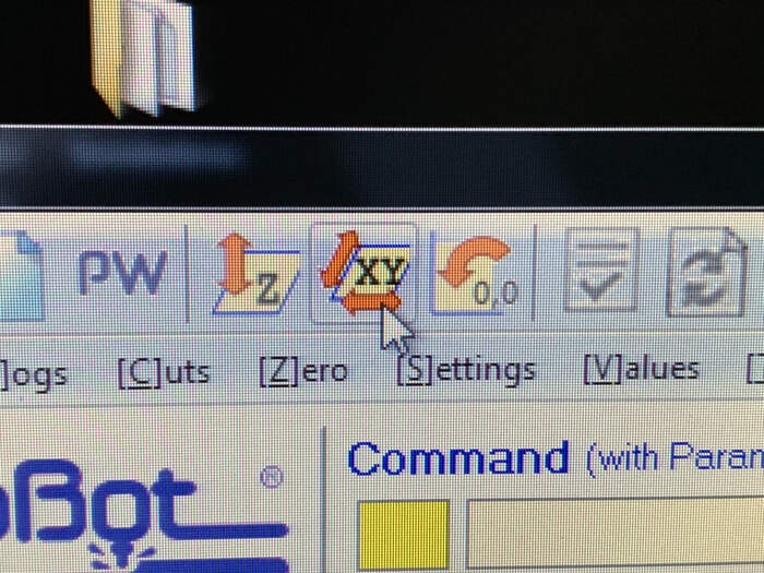
Firstly we will press the XY button so that the machine takes over and carries the spindle to its original 0,0 point. The machine will make a sound as a warning that it will start moving.
-
After the machine having traveled to the 0,0 position we will place our material on the sacrificial layer in the place where we would want it to be milled.
-
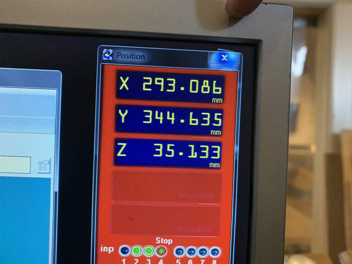
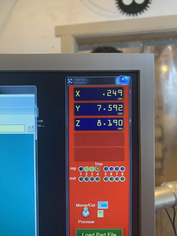
Press “K”, keypad opens up and with the arrows we will move the x and y axis of machine till the spindle is on top of the right hand corner(origin, from where the machine will interpret the design) of the material. It is important to take a picture once we have our X, Y coordinates so that we know where we would exactly have to start if he had to mill the board again, if there was a power outage or if there was an emergency stop.
-
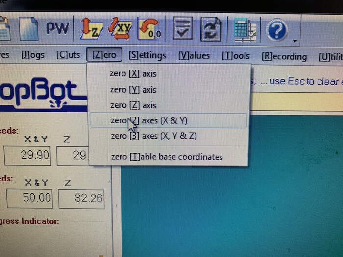
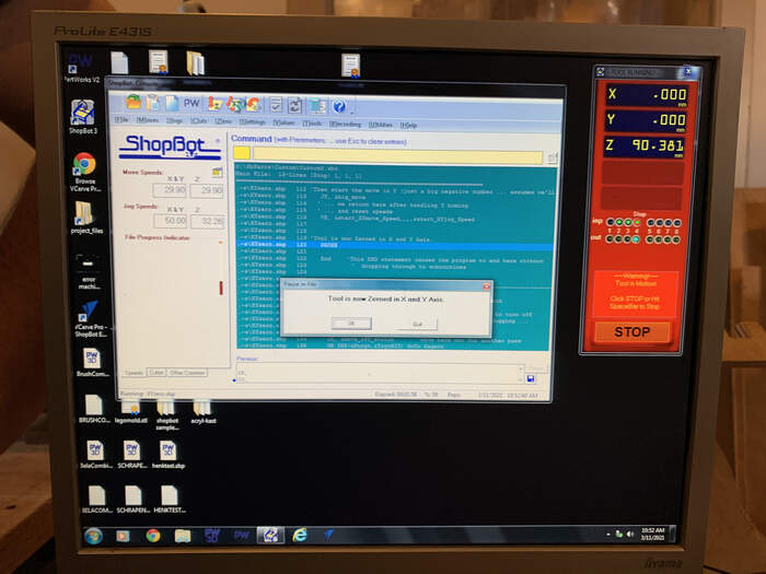
Once we take the picture we would press Zero > new zero x+y axis. This will make the machine interpret the new origin as the place we have just selected.
-
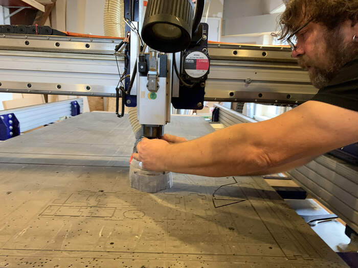
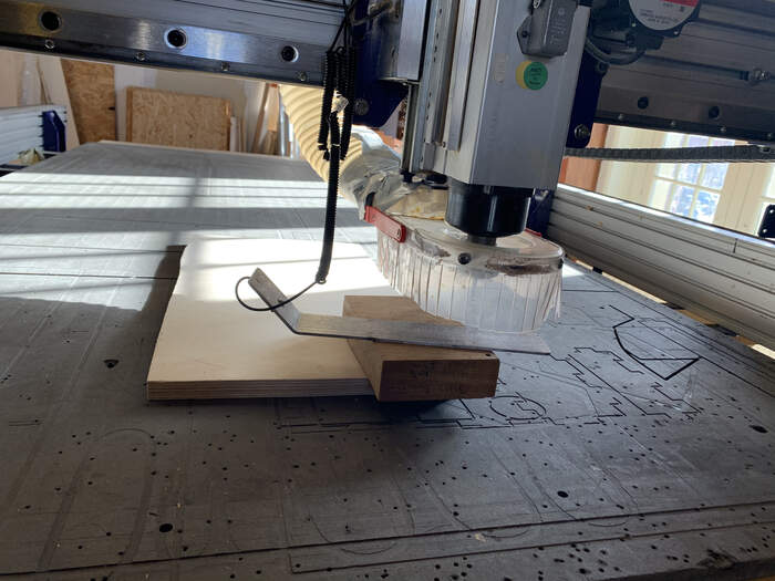
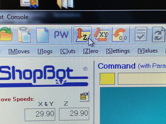
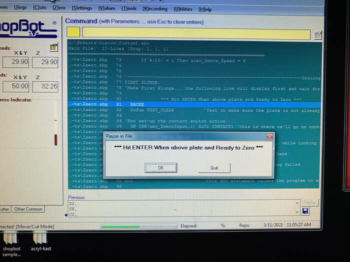
To set up the z-axis we first move the x and y axis to the centre of our material. This will make the z-axis more accurate. We take out the metal piece attached to the Shopbot (specifically for this) and make contact between the spindle and the metal piece. When doing this a green button will appear on the screen.
-
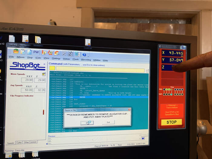
We now place the metal piece on top of the material. We press the z button and the machine will automatically make the measuring for us. When the machine finishes the leveling, before removing the metal piece use the up arrow to remove the metal piece without touching the spindle.
-
We would now have x, y and z axis leveled for our job. It is advisable to re-level the z-axis after attaching your material to the board with screws as the material would become lower and the cut would be more precise.
LEARNING HOW TO USE V-CARVE:
-
To set up the settings for the different toolpaths the machine will be doing in order to cut we will use V.Carve Pro, the Shopbot edition. With this software we produce G-code for the machine.
-
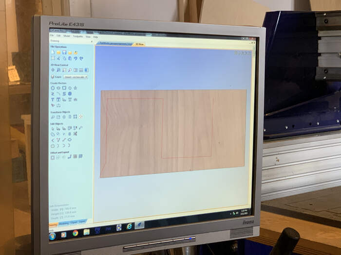
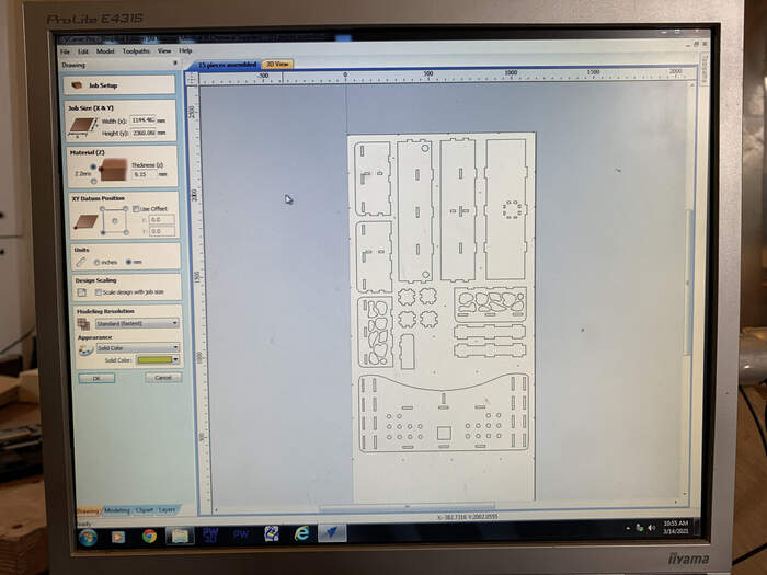
We would have previously created an EPS file (I explain how to get to this point in the individual assignment section). So we open V-CARVE > File > New file
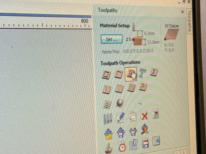
A screen called job setup appears. Here we will tell our machine our job size, material and xy position.
-
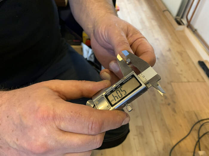
Job size: insert dimensions for x and y (measure material, follow the arrows shown in main machine axis positioning as it is not the usual x-y).
-
Material: this part is really important as it is the thickness of the material. Usually what is done is that with a caliper the material is measured in different spots. We would choose a point somewhere in between because it is easier to take the last mm out than to hit the sacrificial layer.
-
XY Datum Position: shows the position of x and y, the origin (0,0) respecting to the design.
-
We would choose mm
-
Standard modeling resolution.
-
The rest would be left the same and we would press OK.
When pressing OK another window opens up with the design where we can modify different parameters of it (draw lines, shapes, measure, create dogbones, fillets, etc.) V-Carve has many options to modify the design, although it is much better to modify it in your 2D-3D prefered design software.
- What we would want to do in V-Carve is create the toolpaths that the machine will follow in order to cut the material. There are different types of toolpaths (drilling, pocket and profile toolpaths(which has outside and inside toolpaths)). So in total your design will be divided in 4 types of toolpaths (when needed).
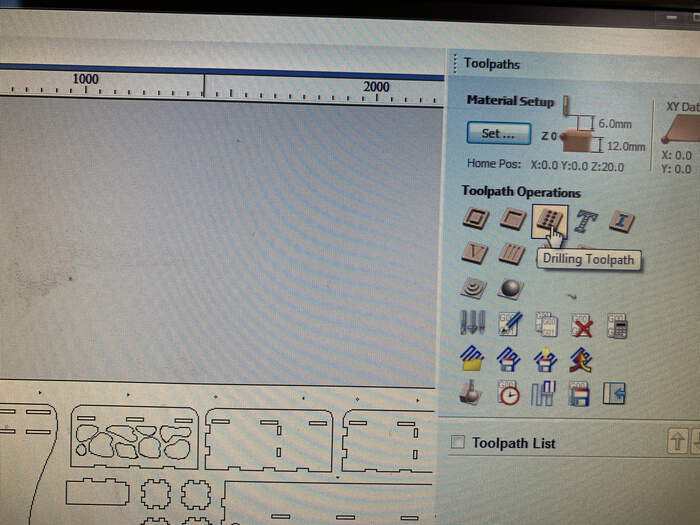
DRILLING TOOLPATH:
-
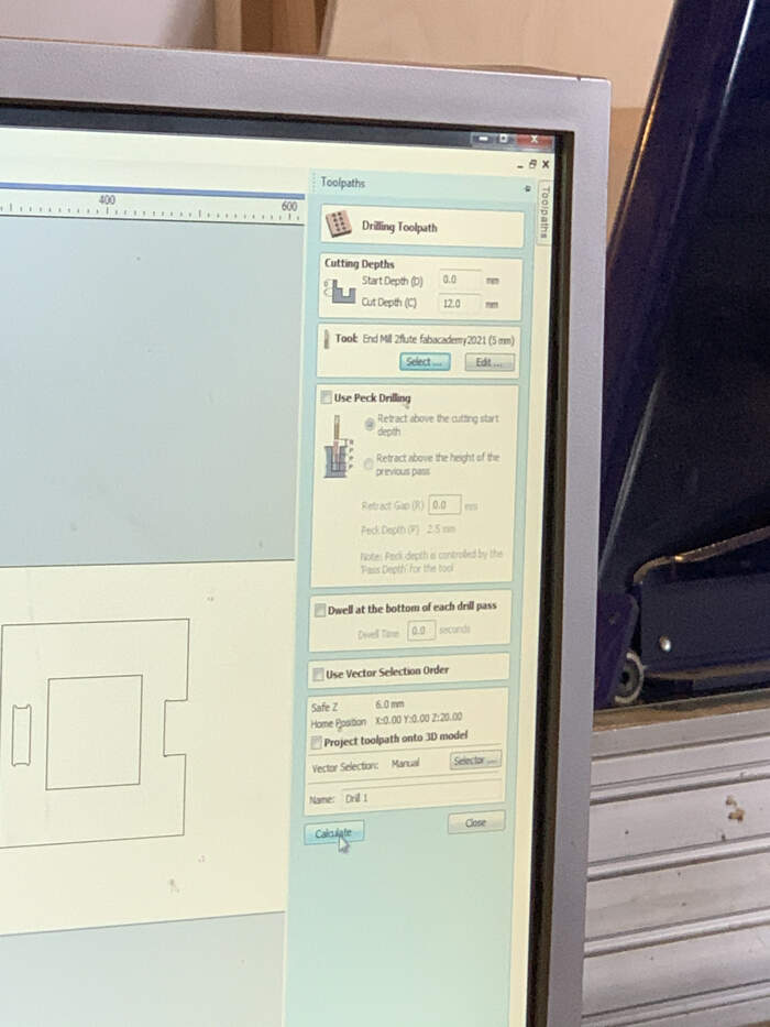
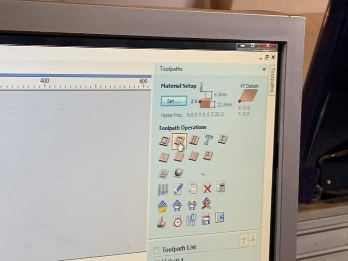
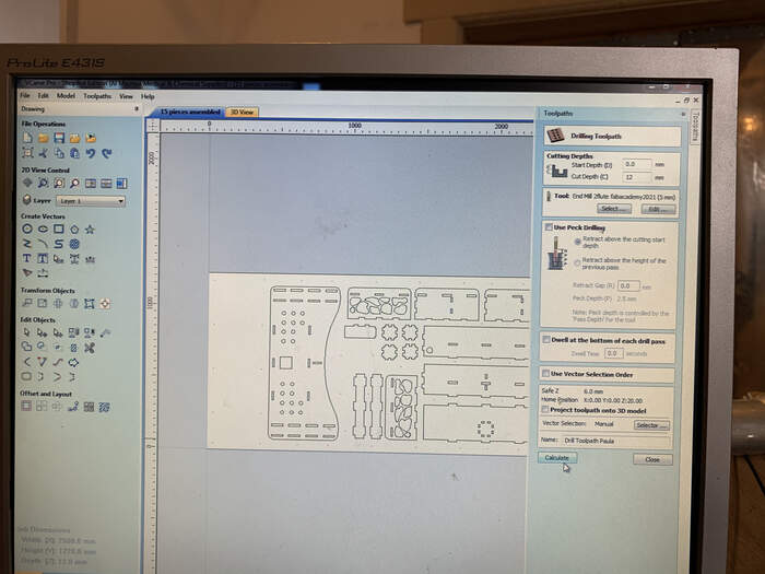
The first toolpath we will create is the screw toolpath. We will mill the drill holes, drill the board to the sacrificial layer and then drill the rest of the toolpaths. This way the milling bit won’t have contact with the screws (avoiding fire). To create the drilling toolpath we will first select all the drilling holes from the design. Then we will press the drilling toolpath button.
-
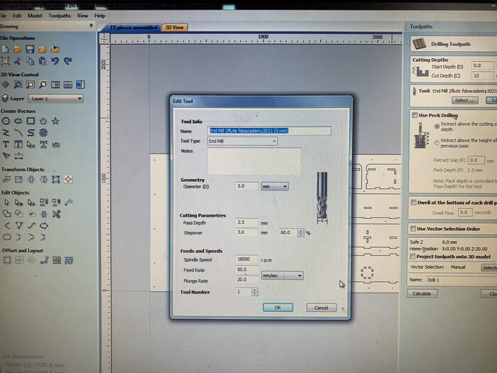
Start job represents the z-axis height, the point from the top where the milling bit will start. We press 0.0mm. If the board is 18mm a nice cut depth for drill holes would be 12mm.
-
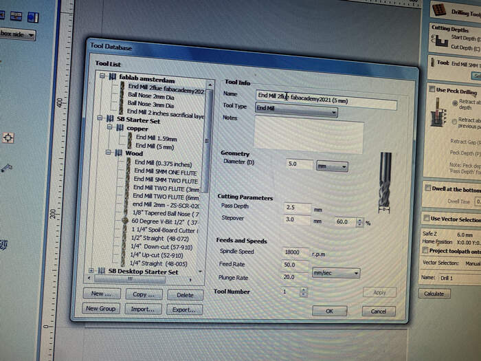
In Tools we would select the Endmill we will be using. For this part we can create a tool and select it in all the toolpaths we will create.
-
In this case we will be using a Wood Endmill 5mm two flute.
-
Under diameter we would put the endmill diameter, in this case 5mm.
Under cutting parameters;
-
Path Depth: 2.5mm (1/2 endmill). With one flute you can go much higher, 5, 7, 8,…
-
Stepover: 3.00mm / 60%
-
Spindle speed: 18.000 r.p.m
-
Feed rate: (travelling of bit sideways) 50
-
Plunge rate: (travelling of bit going down) 20
-
Tool number: 1
-
The rest of the parameters are not needed, press OK and create Tool for this job.
-
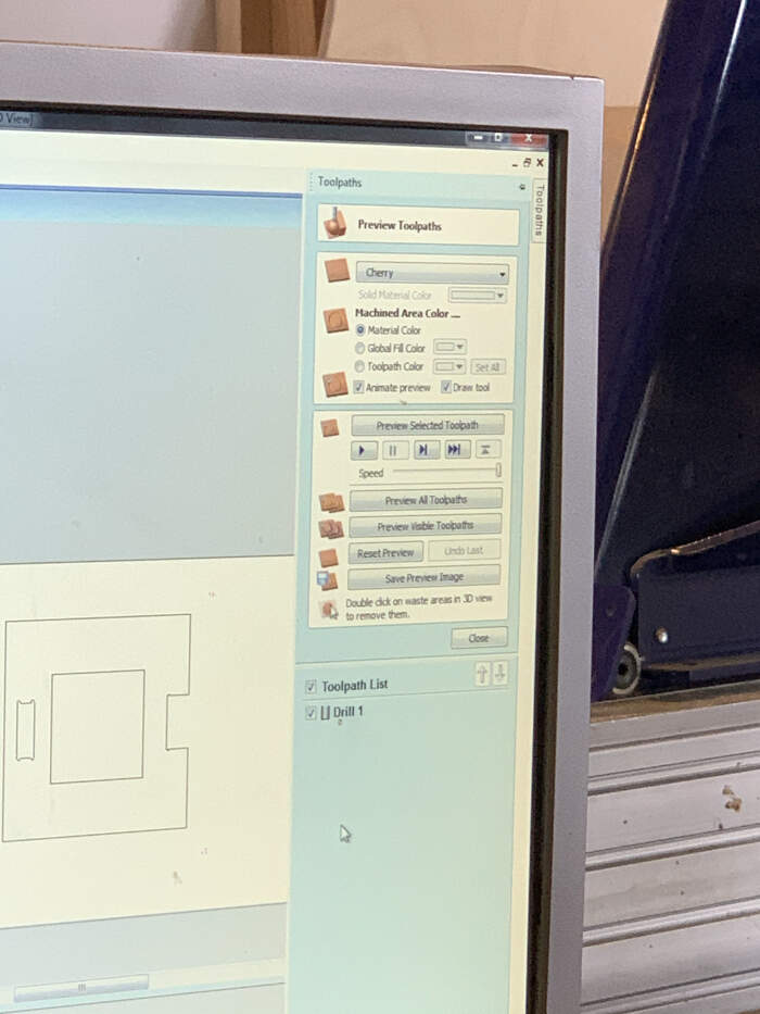
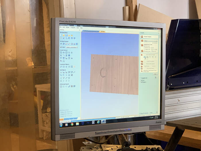
After selecting the tool we can press Calculate and a 3D view will appear where you can check if the cutting is going to be done correctly.
-
Our first toolpath is done. In the toolpath list you can see the List of jobs you are making. From here with the right click you recalculate them and edit them.
-
This is the 3D view:
POCKET TOOLPATH:
-
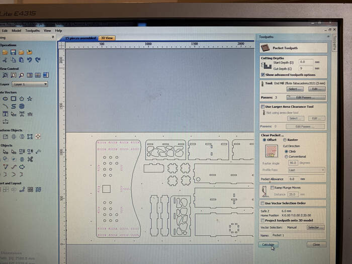
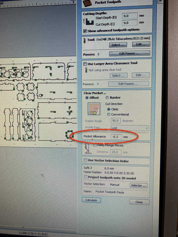
To create the pocket toolpaths (cuts which are not the whole way throught the material) we will select all pockets and press the create pocket toolpath icon:
-
Start depth will be 0 and Cut depth will be the cut depth we would want for the pocket.
-
In Tool we would select the same endmill.
-
It will show the number of passes (amount of times of drill passing through the same spot). Less passes means the machine will go faster.
-
Offset option is suggested, as well as climb.
-
The pocket allowance, we can make it bigger or smaller (tiny modifications, but it is not really necessary, it comes with experience).
-
Press Calculate and pocket Toolpath is done.
-
We check the toolpath.
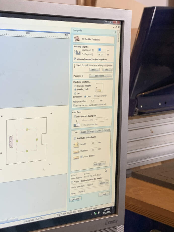
PROFILE TOOLPATH:
-
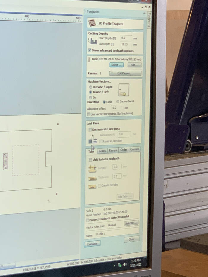
There are two types of profile toolpaths, the outer cut through of the shape and the inner cut through of the shape.
-
They both have the same settings(start depth: 0, cut depth; thickness of material/ choose same tool/ climb) except from the option of inside/ outside line
-
They also include the possibility of adding tabs. Tabs are very necessary in order to avoid parts flying around the room when cutting.
-
We added tabs of 5mm length, 4mm thickness and we tick the create 3d models. Tabs are the green squares represented in the design. If you click on edit tabs you can add or take tabs, change their dimensions, and move them around. It is advisable to not place tabs in corners.
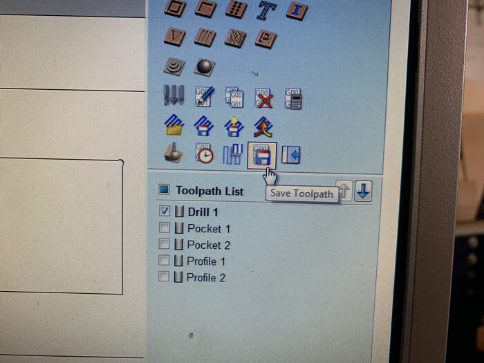
SAVING TOOLPATHS
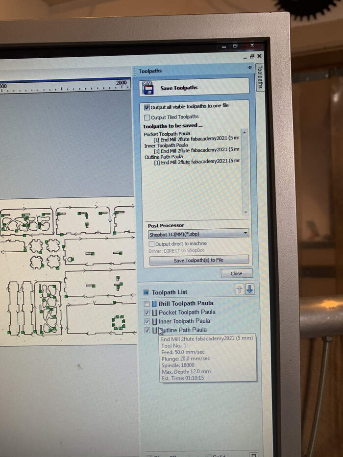
- When all toolpaths are finished we can save toolpaths in 2 files: one with the drilling holes and one with the rest of the cuttings (pockets, inside profile and outside profile). You want to leave the outline profile at the bottom for it to be cut the last, as Shopbot follows the order in which it is saved.

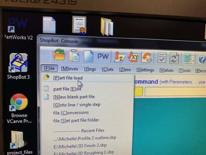
READY TO MILL
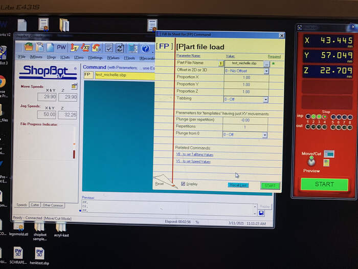
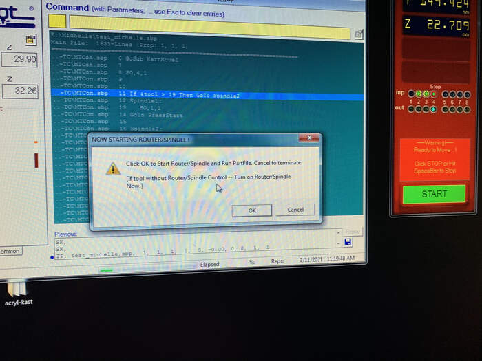
- Once all the toolpaths are done, you go back to ShopBot, File > Load path file. In this case we open the file prepared to test our group assignment. The one only with the drill holes.
Before pressing START we have to:
-
check the green button extractor is on
-
check it is a safe environment
-
turn on spindle by turning the key
-
turn on the second air extractor red button
-
wear all safety equipment
-
Press START, machine will start reading the G-code. > OK Software takes over.
-
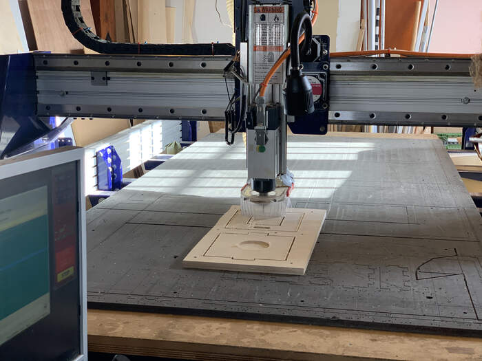
It is advisable to first do a tryout on the air (leveling the z-axis with a higher material).
-
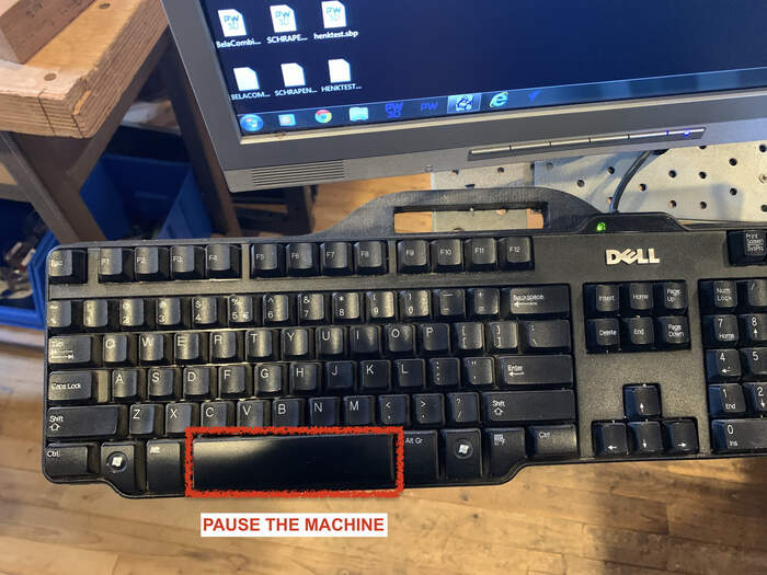
The first seconds the machine starts you have to have the hand ready to pause the machine in case something goes wrong.
-
Note that when you start the job, you can’t do anything else on the computer, just press STOP.
DRILLING HOLES
-
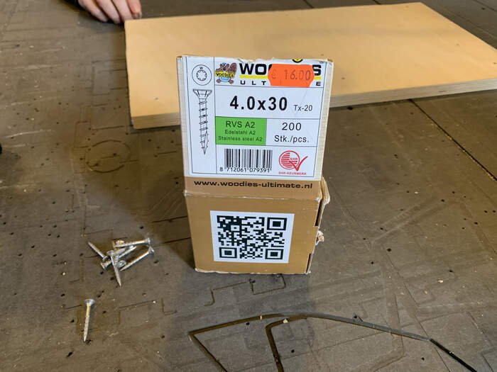
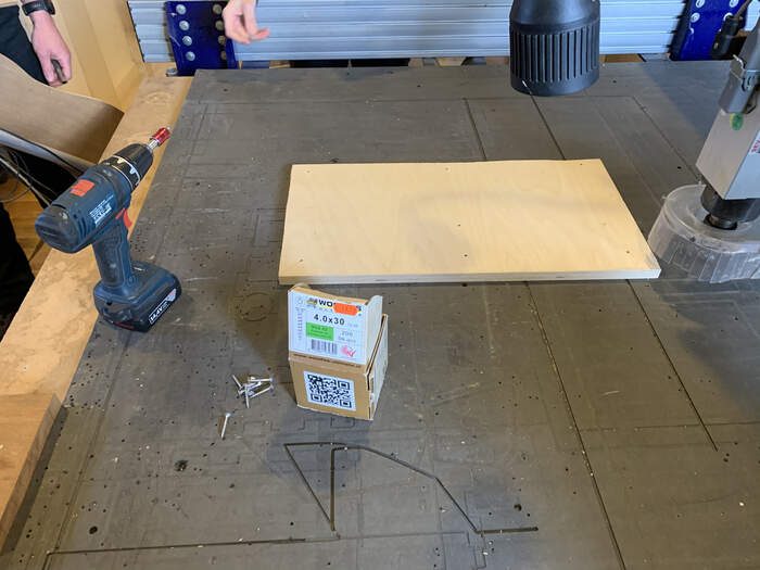
After our first milling we turn off the machine and attach the board using woodies(which are screws which can handle lots of force). They basically hold the material down and in place.
-
After drilling we turn again the extractors, machine on, open the pocket, interior, and exterior toolpaths. Machine starts milling.
-
Always sit by computer and watch the job
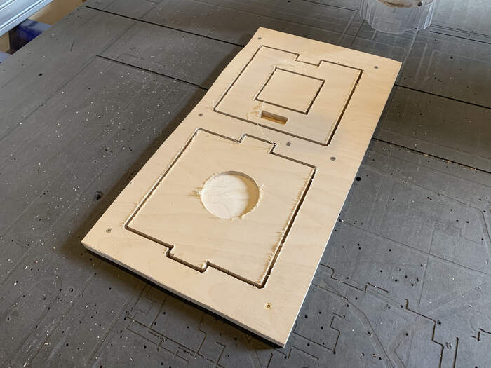
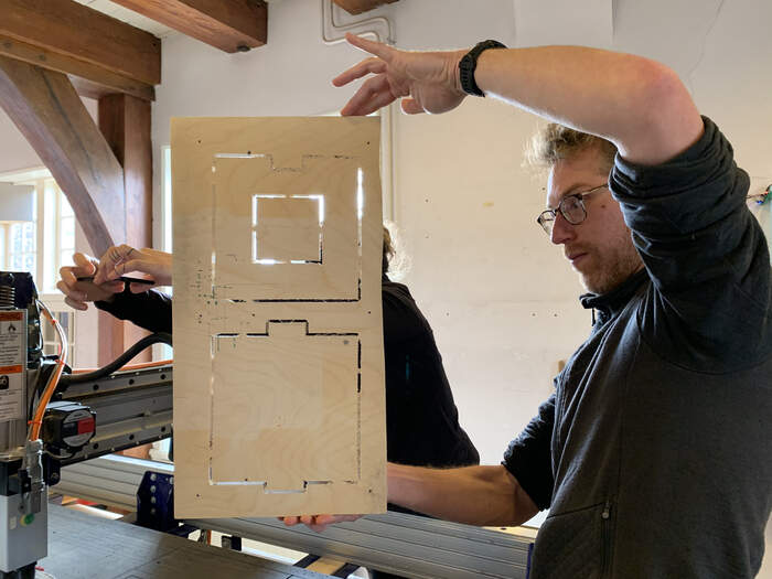
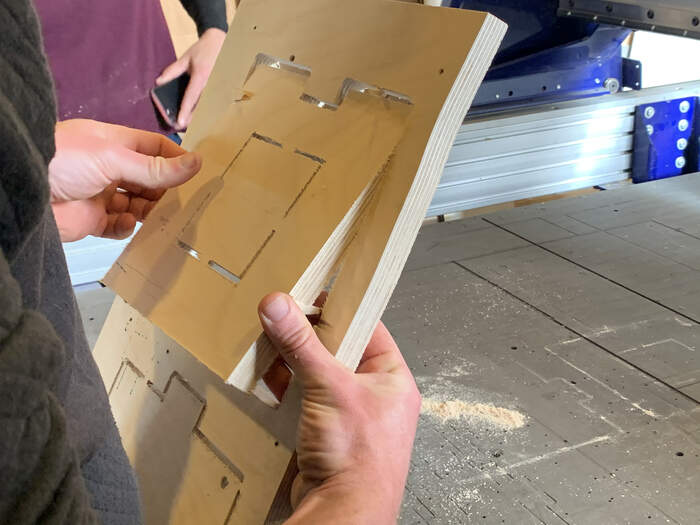
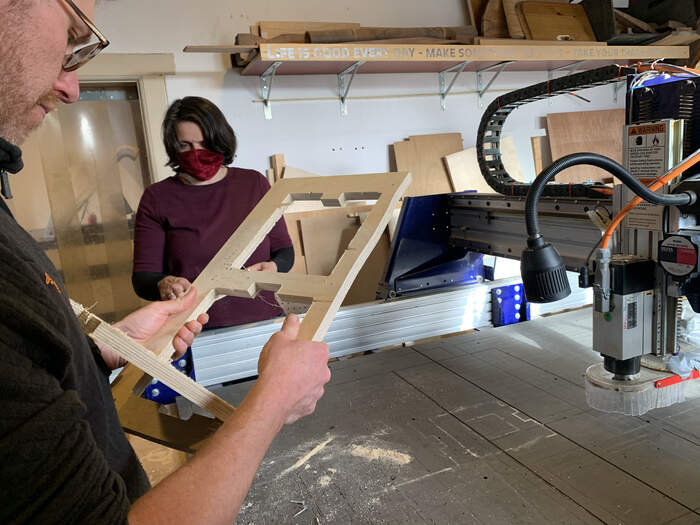
RESULTS OF OUR FIRST MILLING:
-
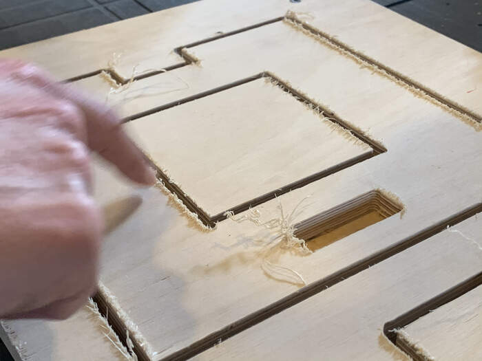
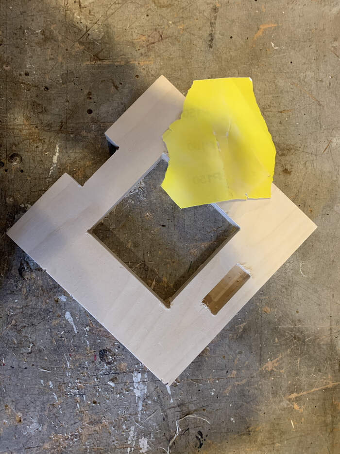
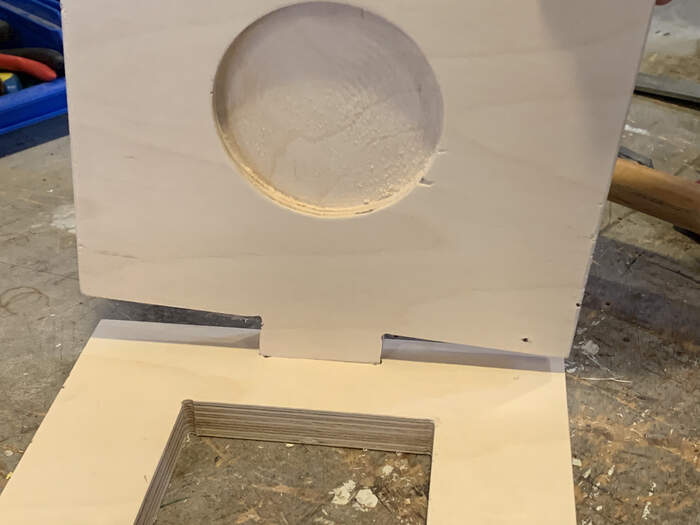
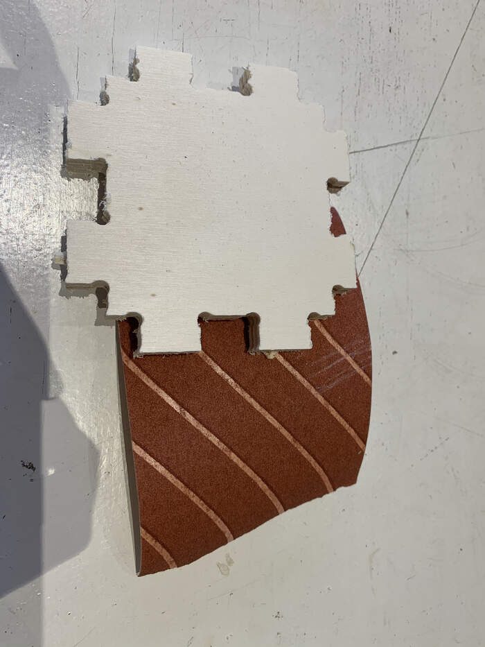
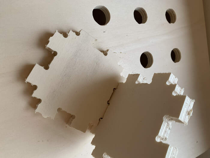
When job is done, TURN OFF MACHINE and you unscrew the board. Our board had very rough edges.
-
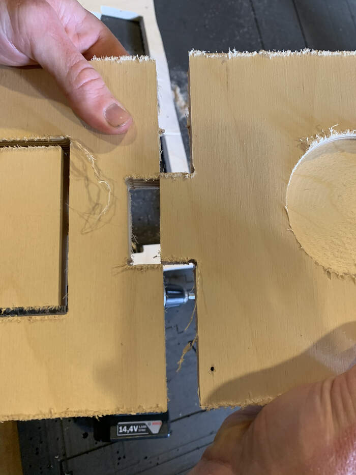
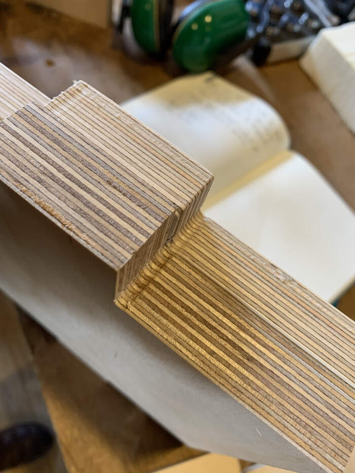
We sanded the corners:
-
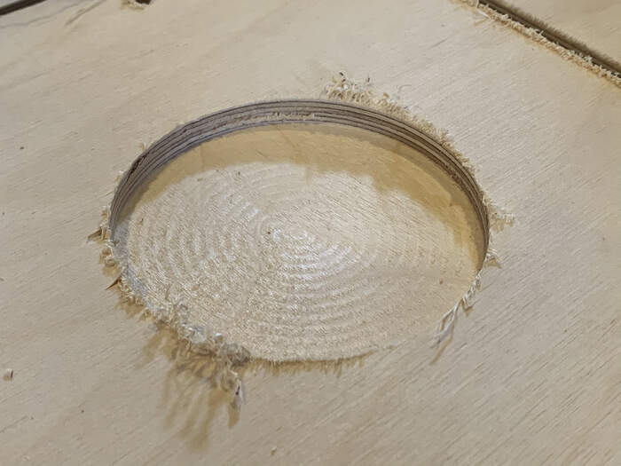
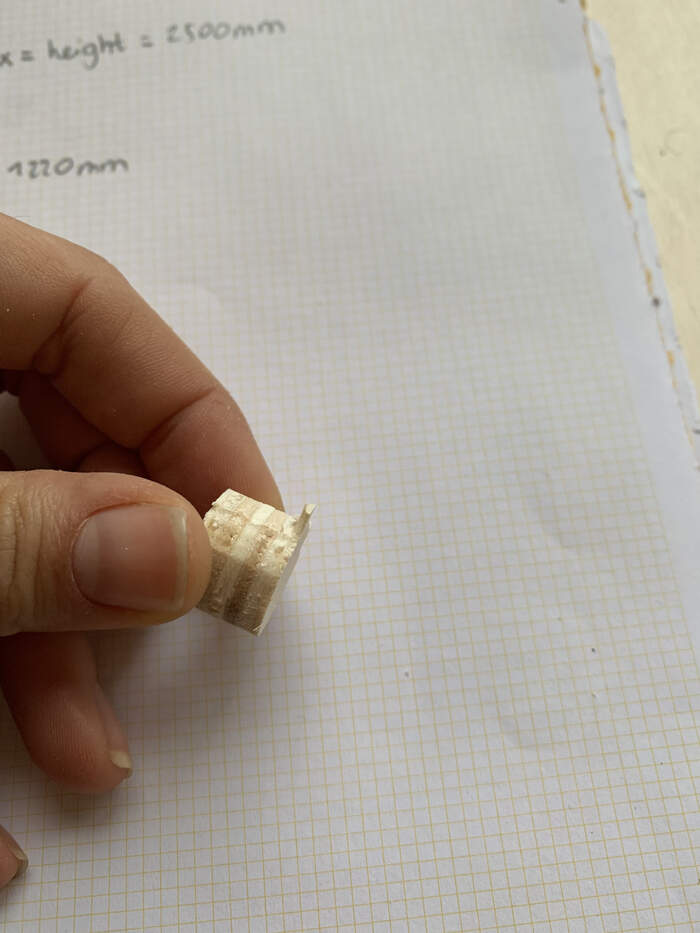
Unfortunately the press-fit did not work. There is 2mm difference which makes it not fit.
This could be because:
-
The milling bit is old so it makes rough cuts, not that precise
-
The milling bit was thinner than 5mm
-
Henk explains that with wood you should always give a bit of offset. This offset decision you get with experience, but he suggests 0,3mm
-
Overall I understood the machine workflow which is really the important part of this week’s assignment.
-
The last step was CLEANING UP :)
INDIVIDUAL ASSIGNMENT: Make(design + mill + assemble) something big
FIGURING OUT WHAT TO TO DO AND HOW TO DO IT
-
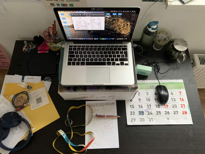
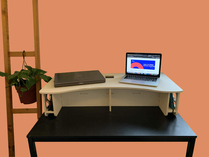
We only have 4 hours to mill our individual assignment to we have to keep it simple. I decided to build a stand for my laptop as right now it is sitting on a box. I also wanted it to have more functions because my table always looks very messy:
-
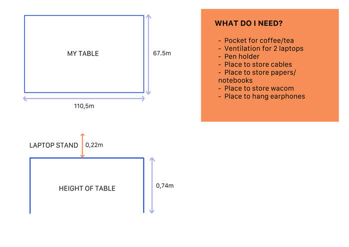
So I measured the existing table of my room and made a list of needs:
-
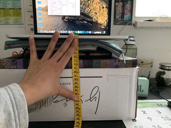
I simulated different measurements on the existing table like the height, width and length to check if I would be comfortable with the dimensions:
-
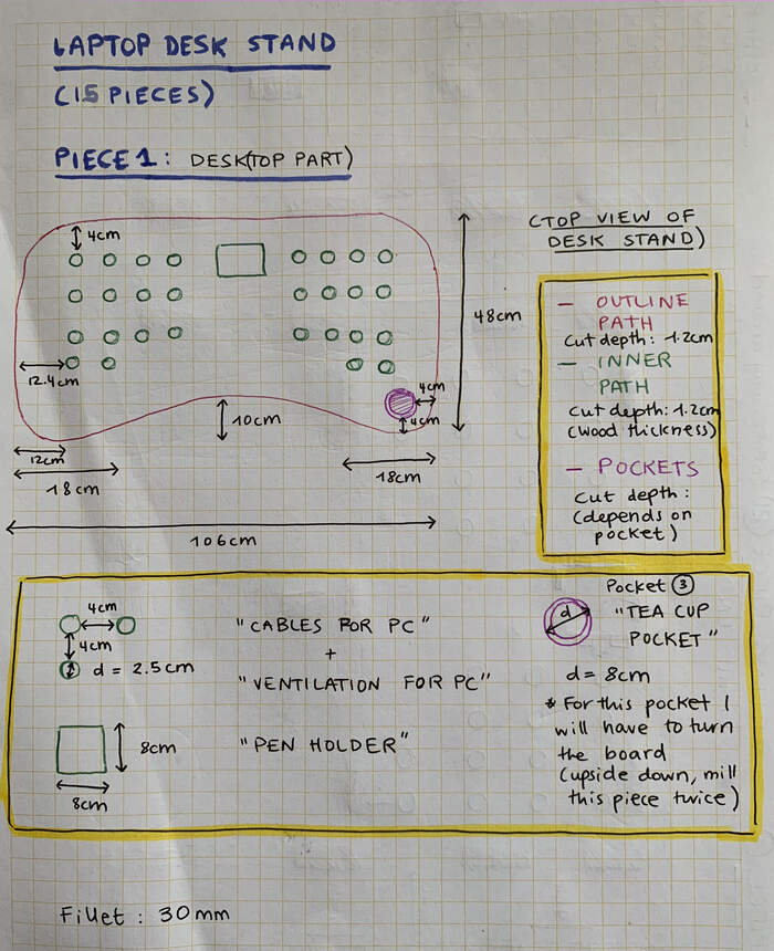
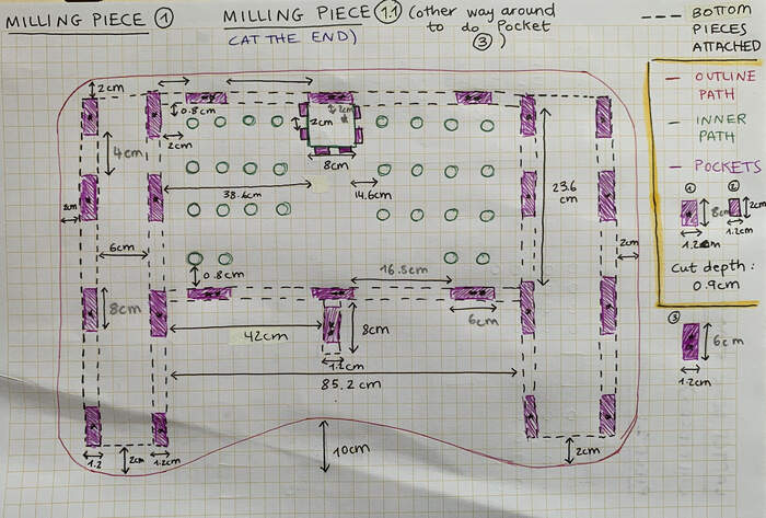
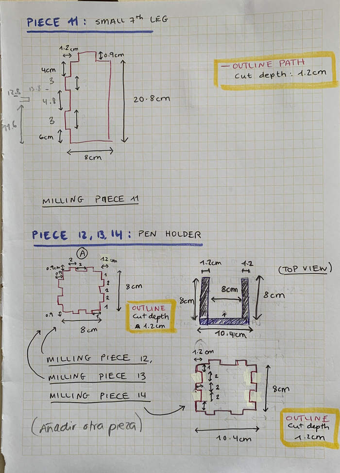
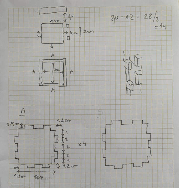
Then I started designing the pieces on paper. This process all came along and it took me 1 day to design the shape, do the correct measurements and be sure that when assembled they would fit together.
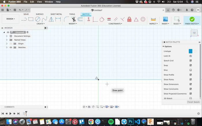
DESIGNING IN FUSION 360
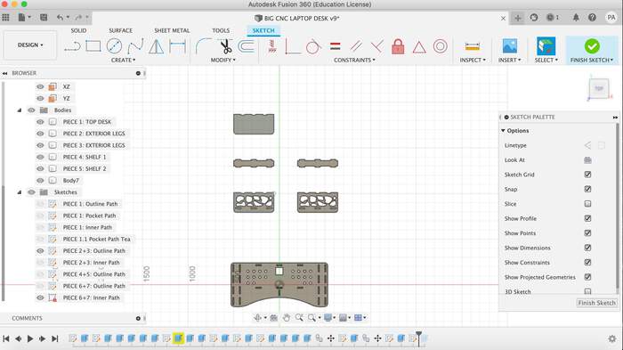
-
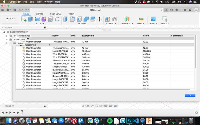
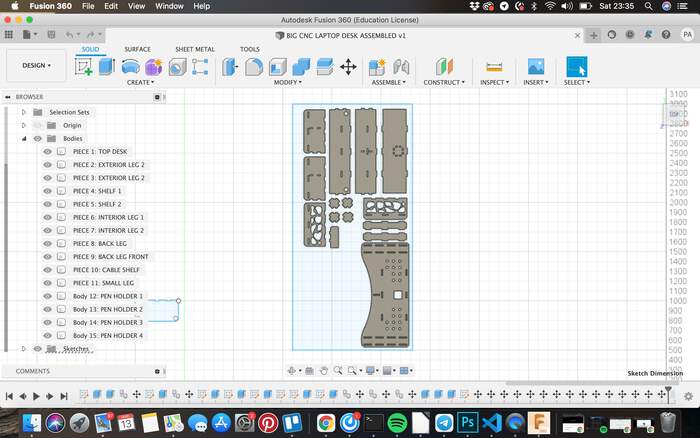
In total I would have 15 pieces. I decided that I would design them flat as I would just have to follow my sketches on paper and I just had one day to draw the pieces on Fusion. I first started specifying the parameters. The list was quite long but I labeled them clearly so I would not confuse them.
-
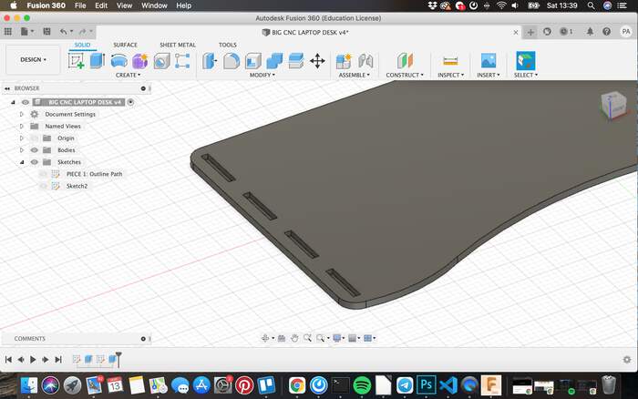
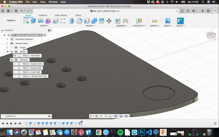
Drawing the outline from the top part of the desk was the most difficult part to sketch in Fusion but I finally worked it helping myself with construction lines and sketch points.
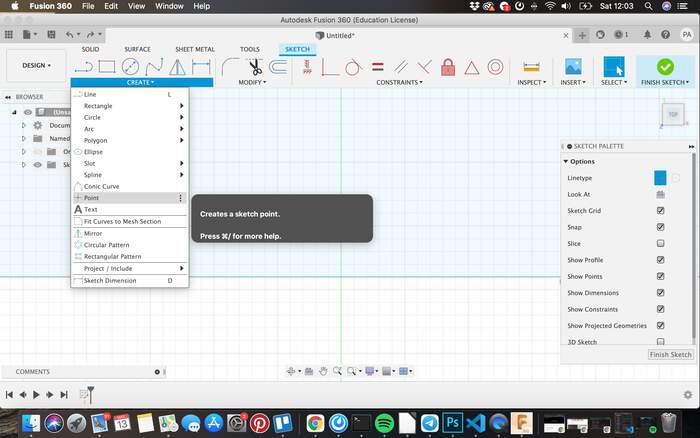
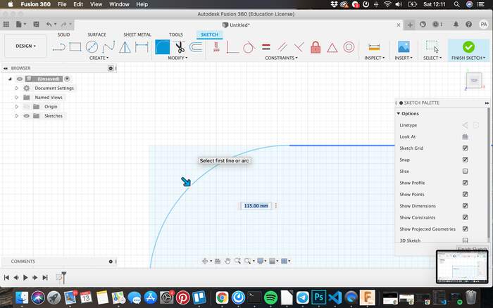
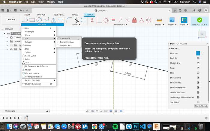
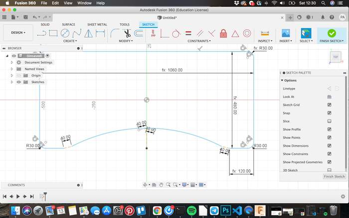
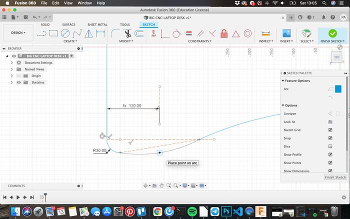
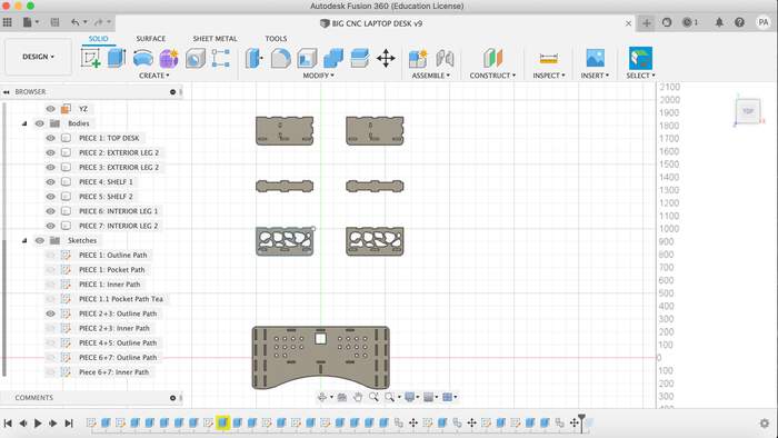
-
I then gave it the plywood thickness (12mm) and worked out the other features from there:
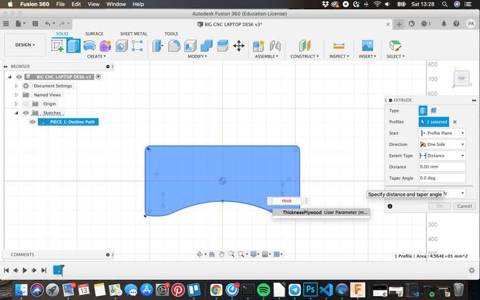
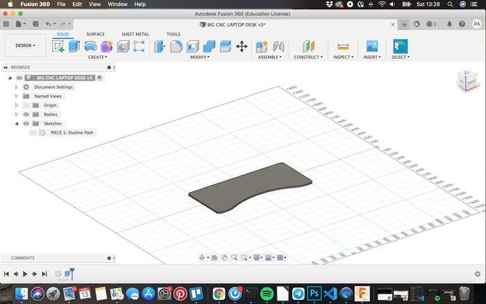
-
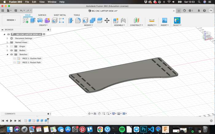
For example the pockets to fix the desk legs
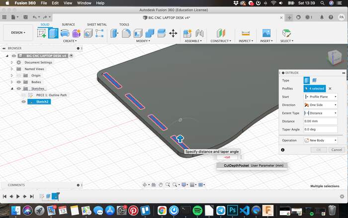
-
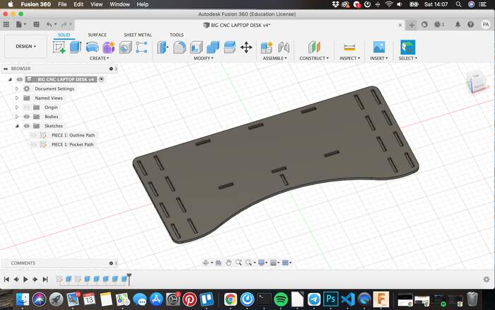
I also then added the inner outline:
-
I drew all these in different sketches so I would name them also as toolpaths for the CNC machine (just to make it easier for my mind).
-
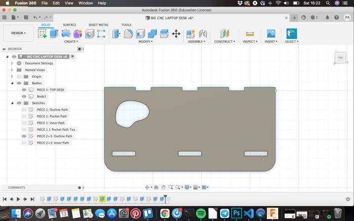
I also drew the tea pocket on the other side of the board, I realised that for this I would have to do it at the end.
-
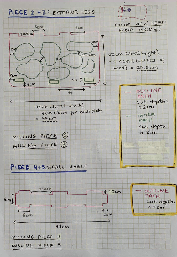
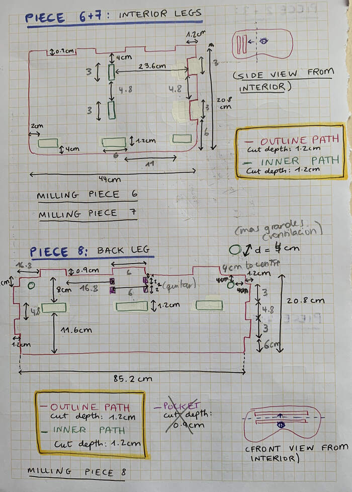
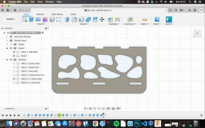
I drew the design in the desk legs the same way as I did for my 3D printing assignment but drawing sketches with the wobbly line tool and then extruding them by the thickness of the material.
-
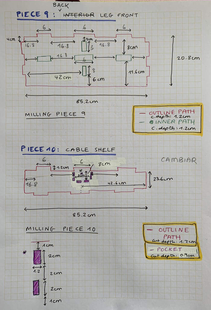
The rest of the pieces were easier:
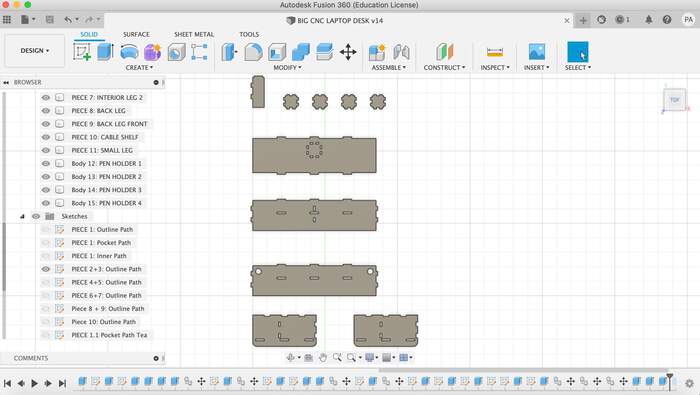
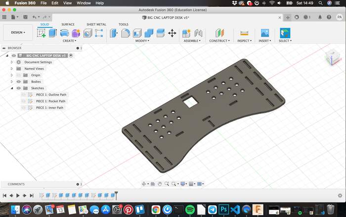
From my original paper-design I changed:
- Added another wall for pen holder and moved the hole from where it was.
-
Changed the number of holes on the desk
-
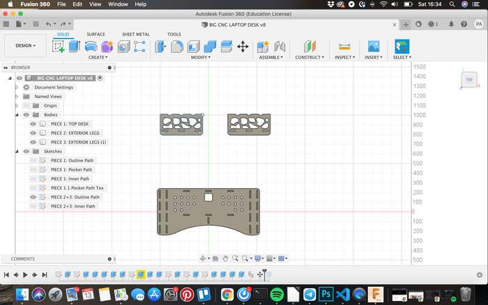
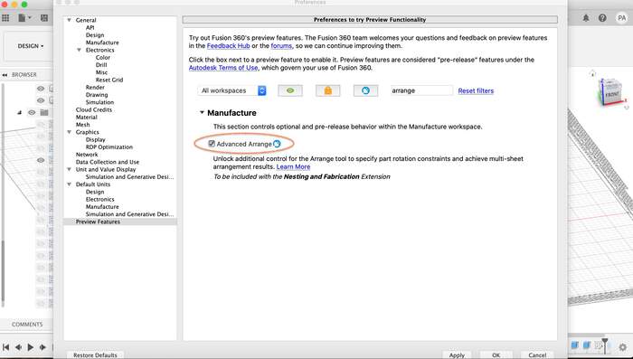
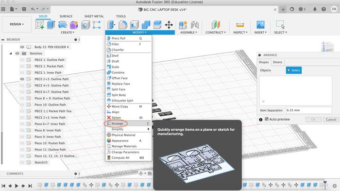
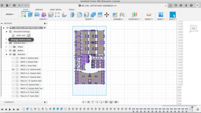
Once all the pieces were done, in order to arrange them within the size of the board (1,22m x 2,50m) I followed this tutorial on the Arrange tool which you can see quickly how it works here. I followed the instructions from the tutorial:
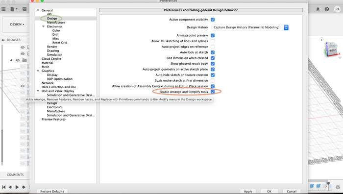
-
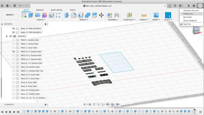
The arrange button did not work for me so I had to create a sketch the size of the plywood board:
-
And arrange the pieces manually:
-
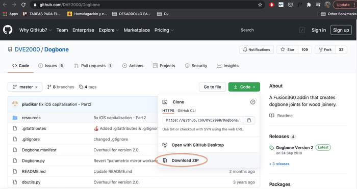
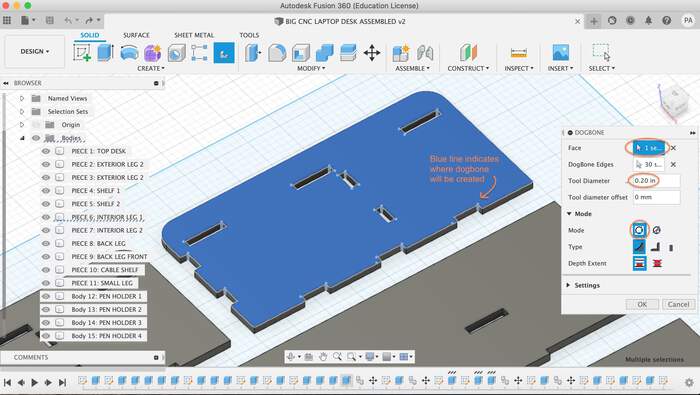
I then had to add dogbones. Dogbones are neccesary if you want to press-fit pieces after cutting them with the CNC. The CNC can never cut sharp inner corners as the tool it is using is round itself, the inner corners can never be more sharp than the diameter of the cutting tool. In order for joints, where a piece of plywood has to fit precisely in a slot, to work we use dogbones so that the piece fits in. In order to add dogbones I used a add-in I downloaded form Github.
-
There is a special thing you have to do when downloading the folder that it is moving it into the add-ins folder from the Fusion 360 library, as it explains in the video, once you do this you change the name of the folder from Resources to resources (Fusion360 is very case sensitive when reading it, if you do not change this it won’t open).
-
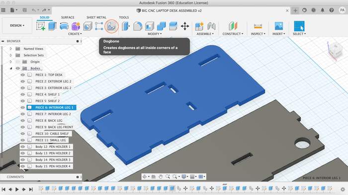
I followed all the instructions from the tutorial, closed and opened up Fusion 360 and I have a new Dogbone button appearing in my screen:
-
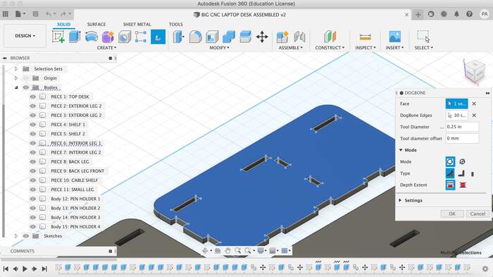
I added dogbones to the first piece, chose static instead of parametric.
-
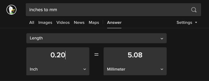
The dogbones you would want them as small as possible but not smaller than the endmill diameter which was 5mm, so I took the value that it showed in inches and converted till it was close to 5mm which was 0,20.
-
This was the value I gave to all my dogbones.
-
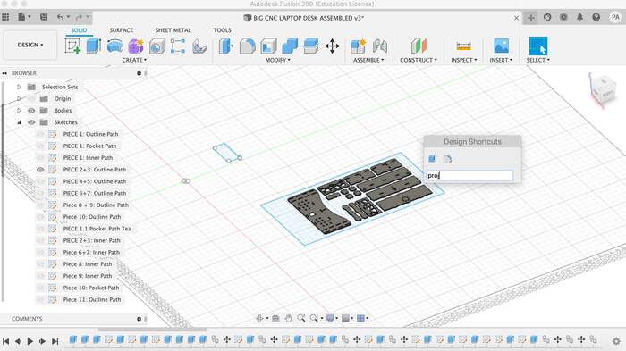
After this I types “S” on my keyboard which allows you to SEARCH in Fusion360 and searched for the project tool.
-
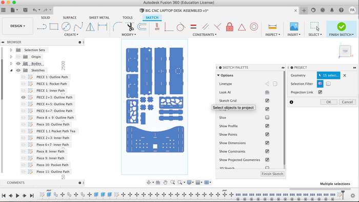
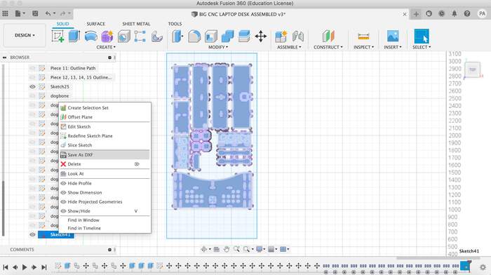
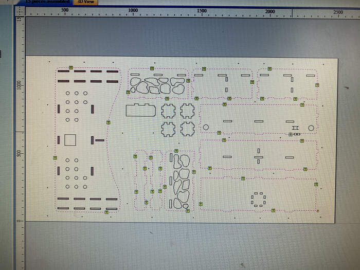
By projecting I all the parts assembled on the board it makes a sketch with all of them which will then be the sketch you export with all the pieces together.
-
Select the projected sketch and export it as DXF
CREATING SCREW HOLES AND CLEANING DESIGN IN ILLUSTRATOR
-
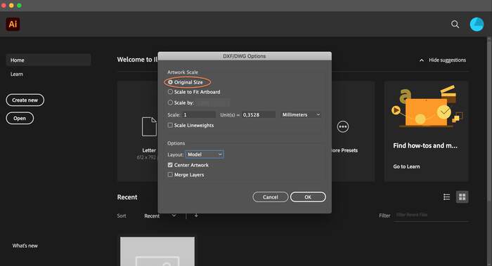
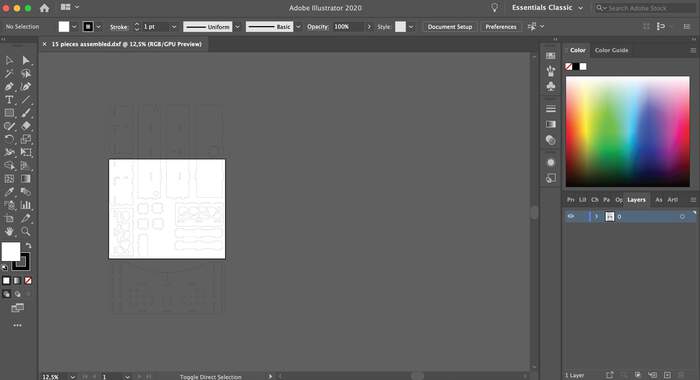
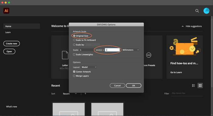
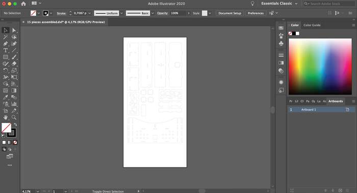
I imported the .dxf into illustrator (this may be handy to check the lines and make sure that everything looks as it should). When opening the file I chose original file.
-
Before editing the artboard this is how it looked:
-
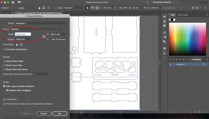
I then opened the artboard options and changed the dimensions so that the X-axis and Y-axis were in the right direction. I then realised I did this part wrong (the x should be in the y and vcvs because this one did not match the x and y dimensions of the CNC but I could change it in v-carve so that was not a problem)
-
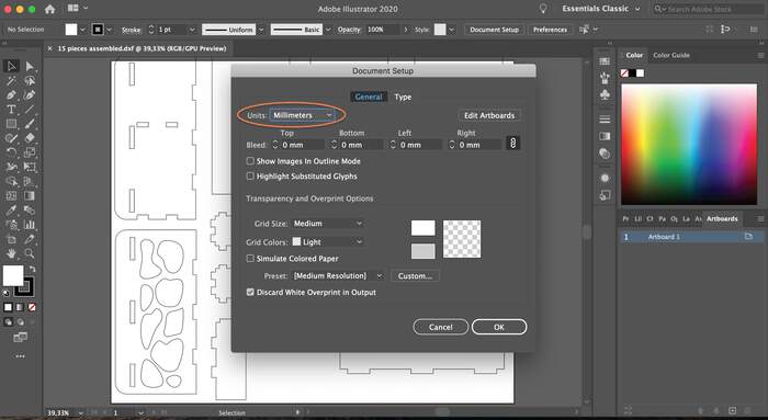
I opened document setup in Illustrator and changed the units to mm
-
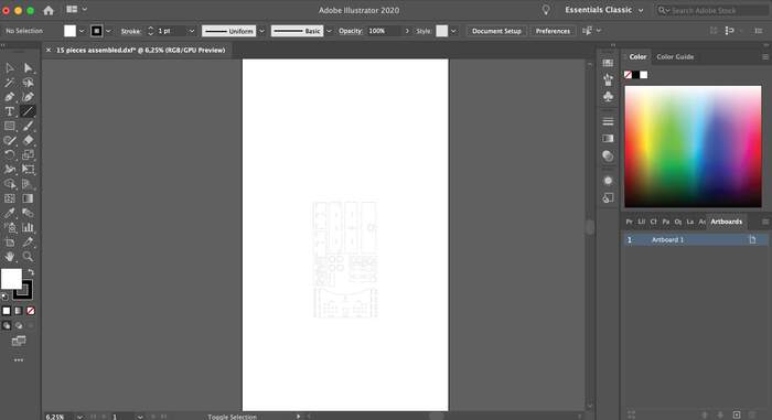
The design appeared too small within the artboard so there was something wrong with the units of my settings:
-
I opened the file again and realised in Units it should equal 1 so that the scale is done correctly.
-
Now it looked better:
-
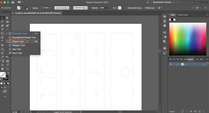
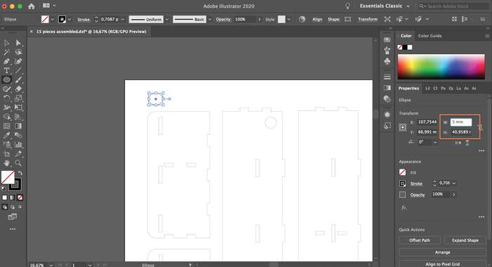
I added drillholes about 30 cm apart on the outside of the board and then I placed some in the middle of the boards. I drew 5mm diameter holes with the ellipse tool and by modifying the dimensions tool to the right:

-
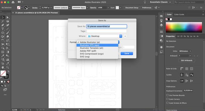
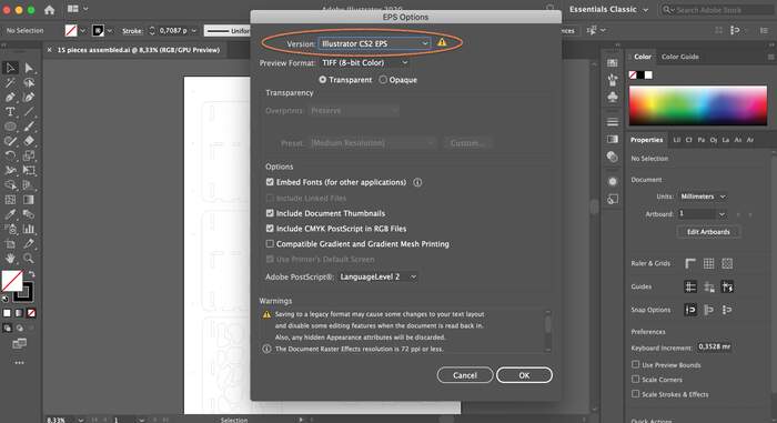
I exported the file as EPS. (IMPORTANT SETTING: the eps must be a CS 2 version - to have a chance with the old windows machine connected to the ShopBot).
CREATING TOOLPATHS IN V-CARVE
-
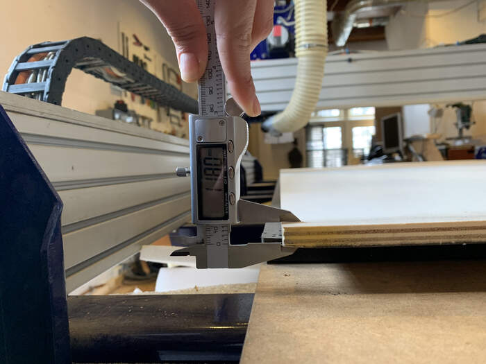
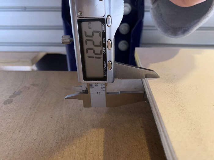
Before anything I measured the board on different sides:
-
In the end I chose a material thickness of 12,1mm.
-
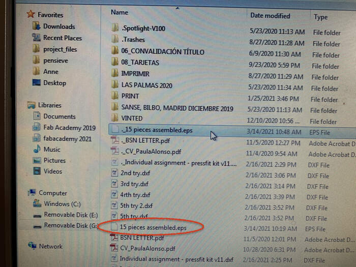
I imported the EPS file into V-Carve, be sure not to open up the hidden file like me (stupid errors occur when you are in a hurry).
-
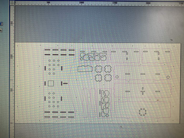
Modify job settup as done in group assignment with board width and length. As you can see below I messed up the x and y with the illustrator file:
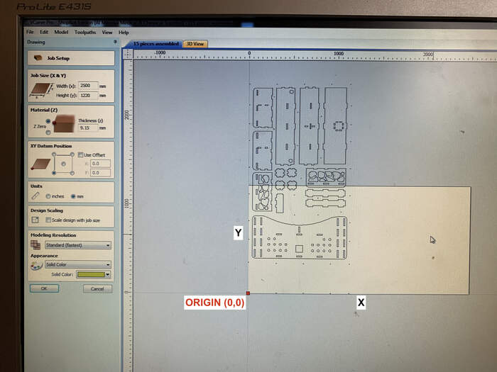
-
I changed it by selecting the whole design and pressing “R” on keyboard to rotate:
-
I created drilling toolpath
-
I created pocket toolpath:
-
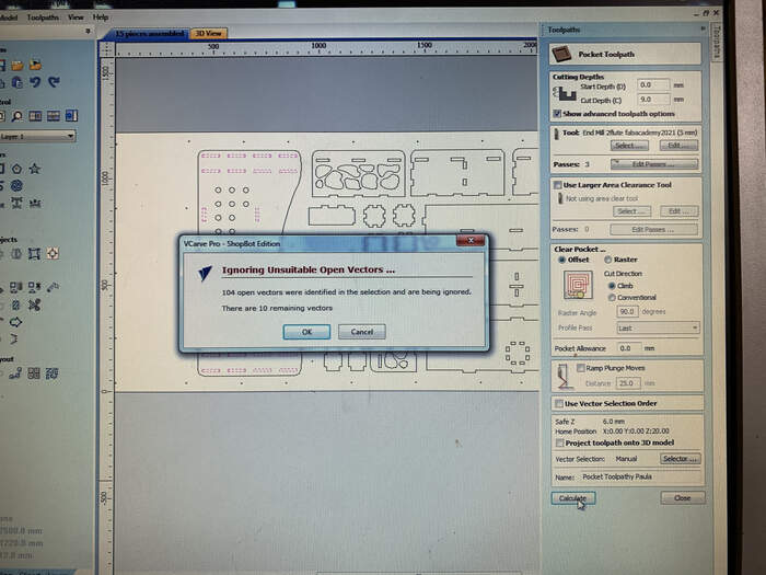
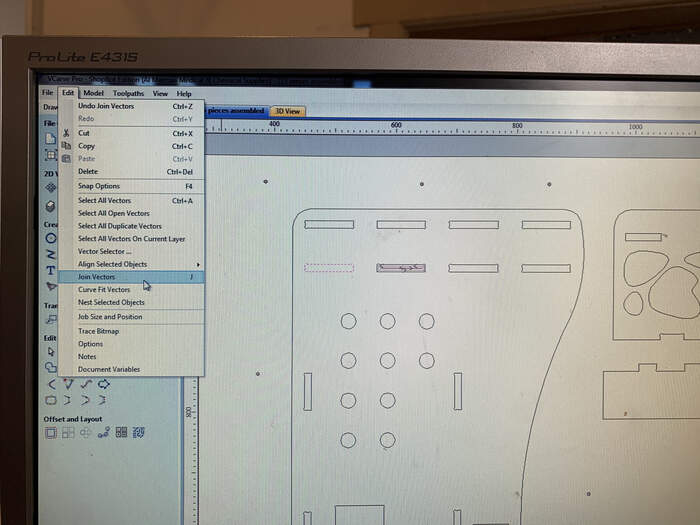
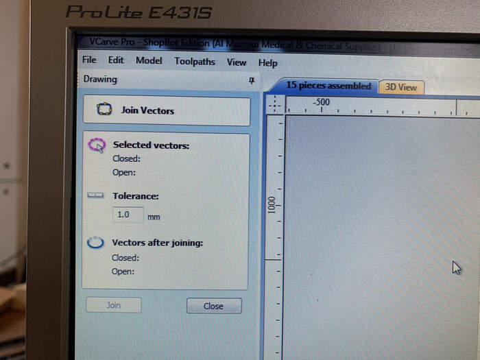
I had an error with open vectors when creating the pocket toolpath:
-
I solved this by Joining vectors with the Join option in v-carve, you can also check open vectors by right clicking on design and choosing the open vectors option, it will open up a window indicating how many open vectors you have in your design. After joining I could finish my pocket toolpath.
-
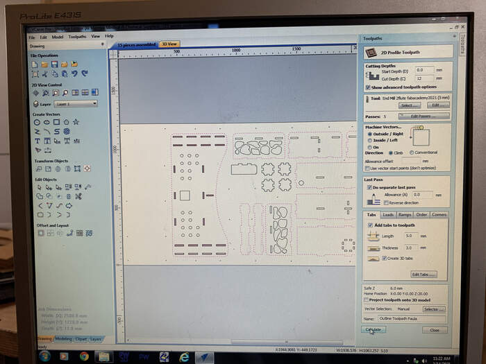
I created the inner and outline toolpaths. I also added more tabs to my design (green squares). If you press on them you can move them around. I moved them out from the corners as Henk had adviced.
-
I changed the allowance offset from pocket, outline and inner toolpaths to -0,3mm as Henk adviced this was a nice offset for the millbit which would allow nice press-fit parts. As it was a tiny measurements I just applied it to all but it was not necessary for the outline toolpath. This is very important.
-
I saved the toolpaths in two files: (first the drill holes and then the pockets, inner and outline toolpaths, in this order so that the piece stays in place and the cut is more precise)
-
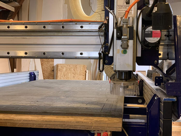
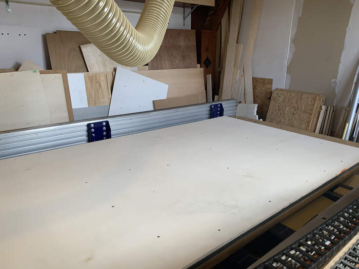
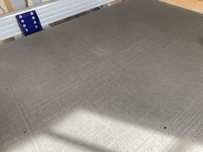
Before setting up the plywood board I sanded the sacrificial layer to avoid screw bumps as seen below:
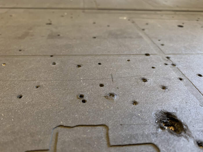
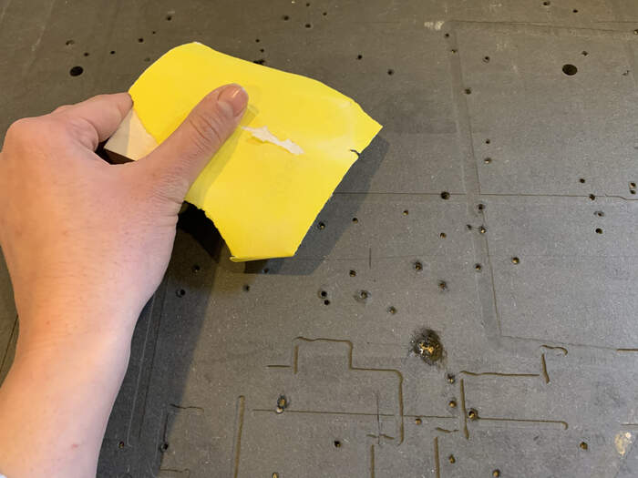
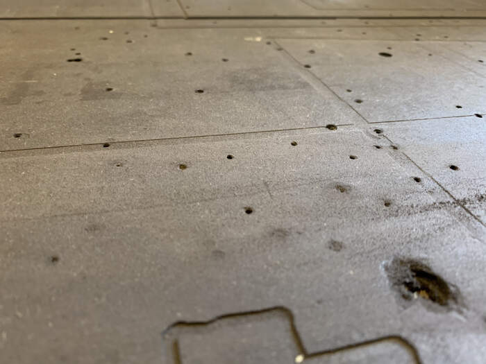
-
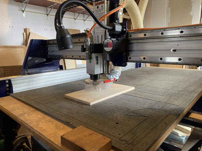
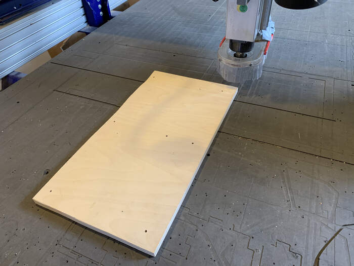
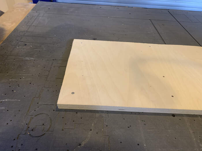
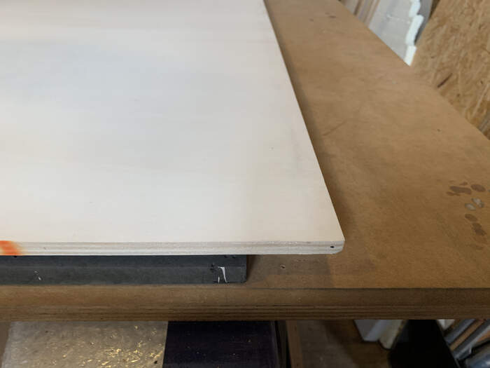
I then set up the plywood board.
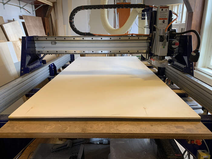
-
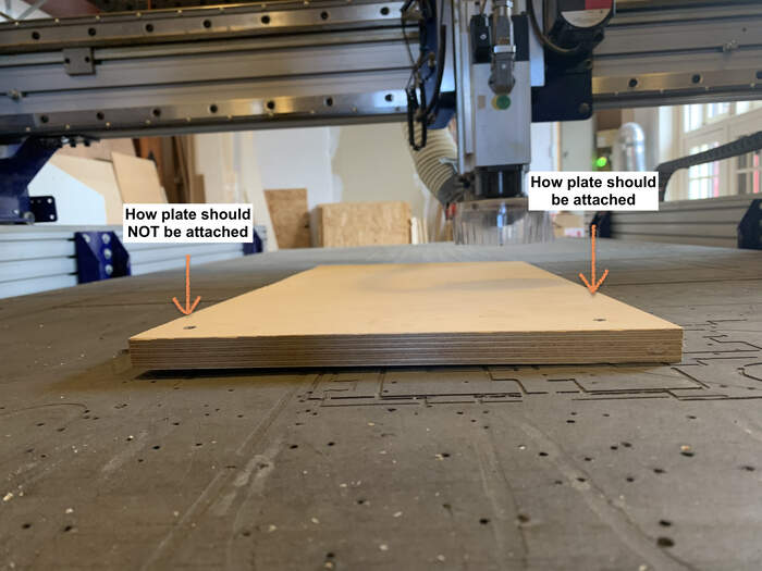
The board is a bit bigger than the sacrificial layer so I was careful that the top part of the design was not stuck to the border as it would not have the sacrificial layer underneath.
-
I followed the steps from the group assignment to level the x and y axis, took a picture:
-
I followed the same steps from the group assignment in order to start operating the machine.
MILLING
-
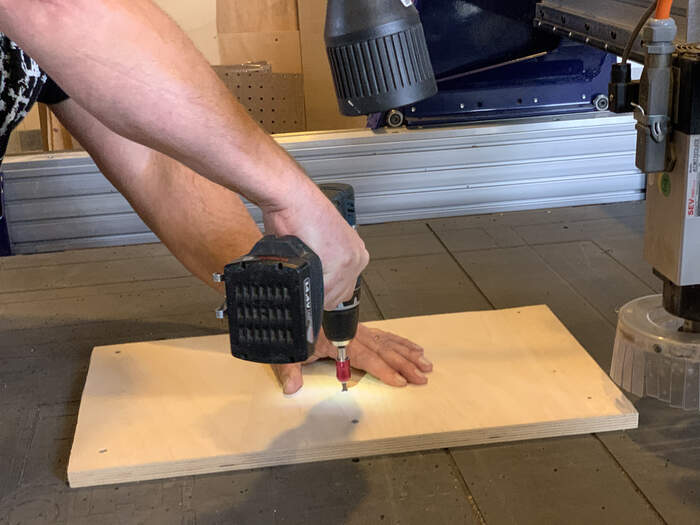
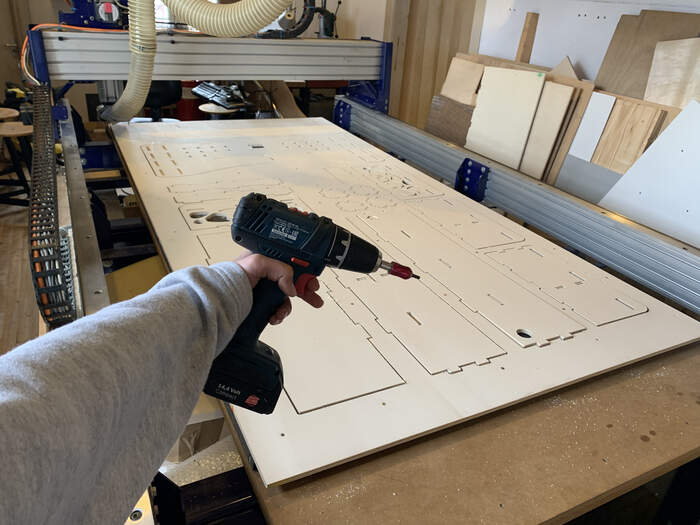
First milling was done: the holes. I drilled the woodies:
-
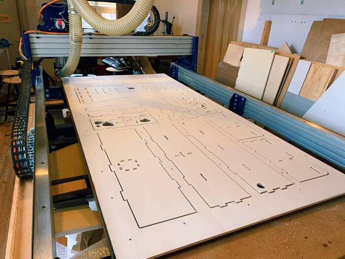
The whole milling was done. I did not take pictures of the process because I had to be concentrated supervising the machine.
-
Unscrewing woodies:
-
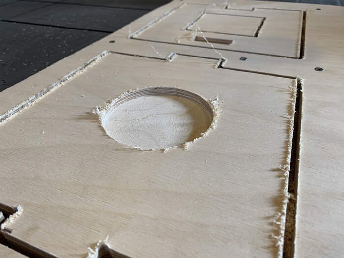
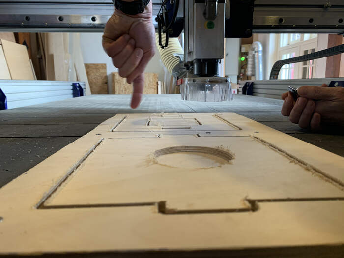
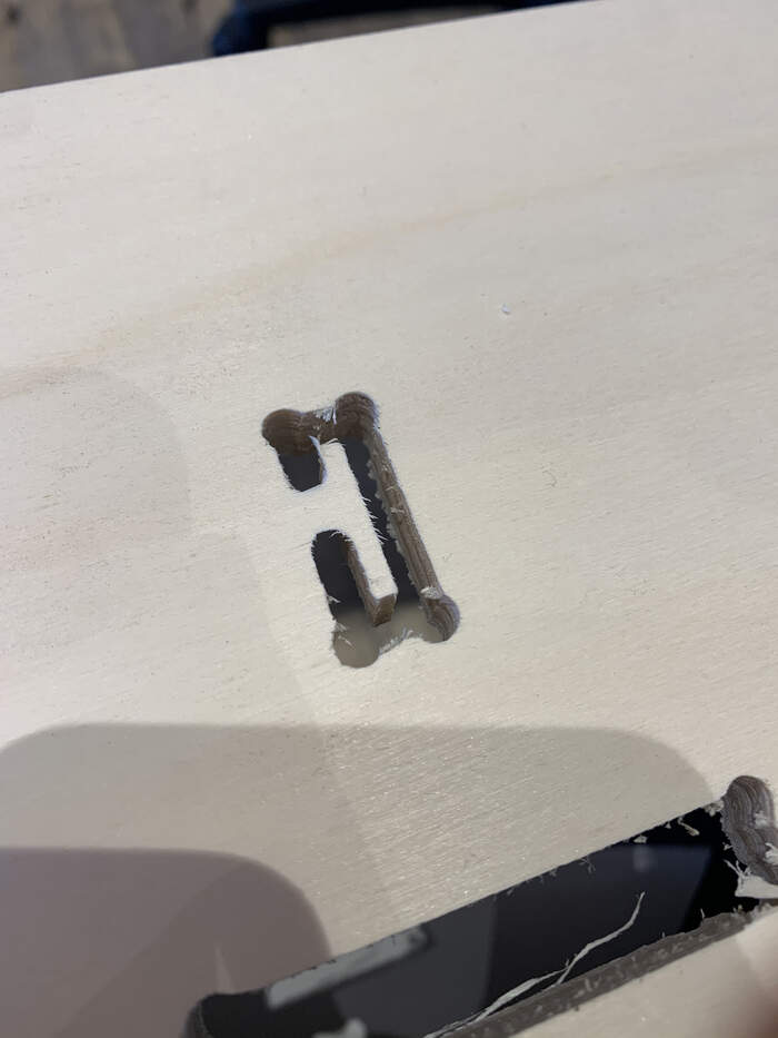
I realised I had put too much cut depth for the plywood thickness because my shapes were all over the sacrificial layer:
-
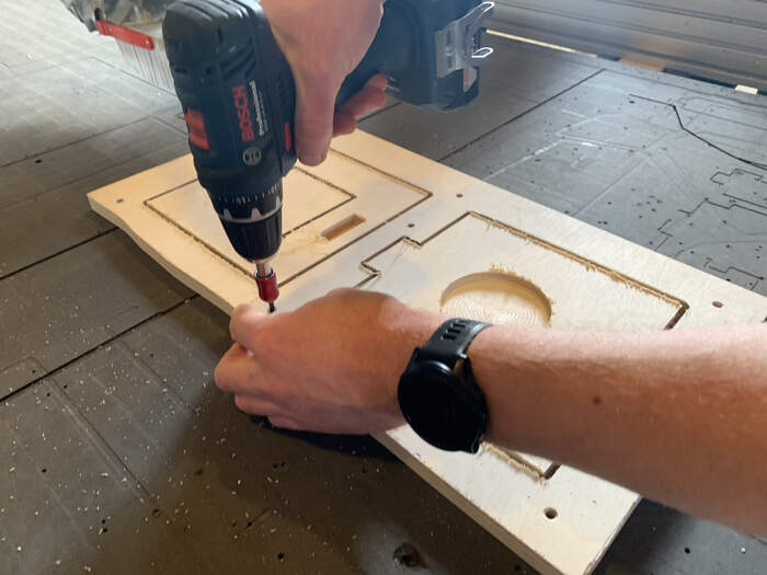
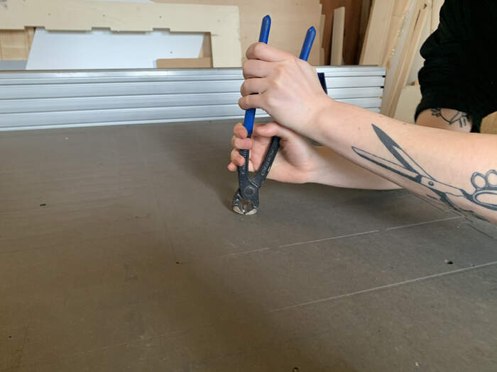
Be sure to remove all screws from the board!!!
FINISHED PIECE AND REVIEWS
-
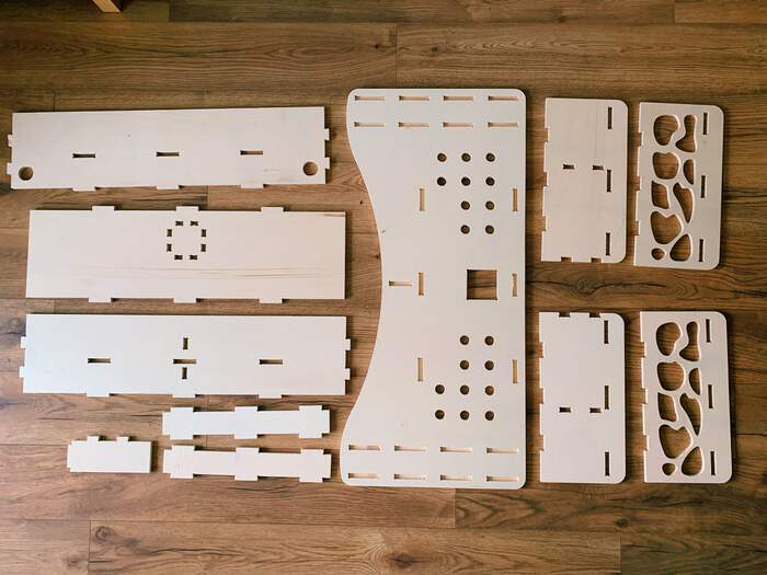
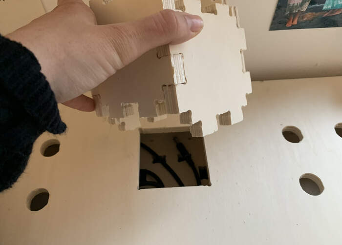
These were my pieces:
-
I sanded them all
-
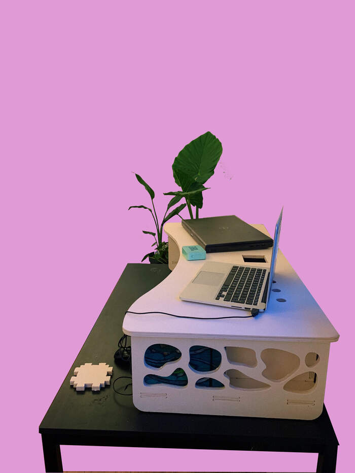
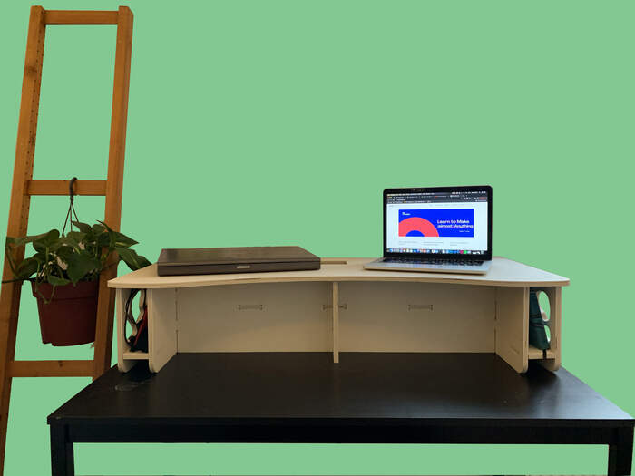
And this was my final output:
-
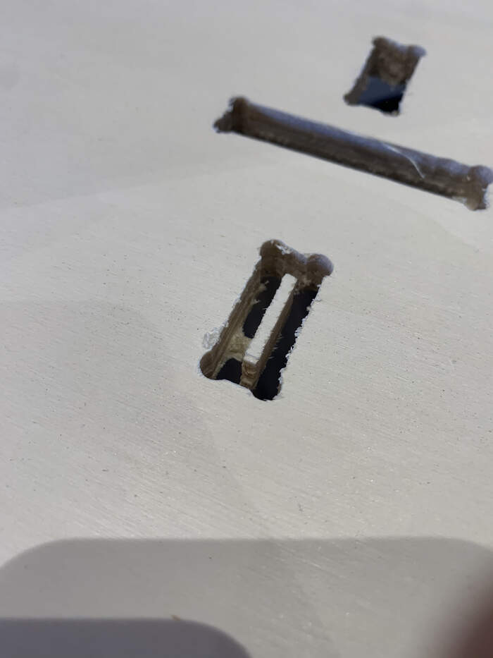
The final reviews are I did my tabs too thin, next time I will do them a bit bigger because it did not really hold the pieces in place:
-
I messed up the pen holder part, I have to repeat this cutting:
-
I did not have time to do the pen holder pocket.
Files to this week’s assignments:
- This is 3D.STL file for the design I made | 3D.stl