Week 02: Computer-aided design
Assignments:
- model (raster, vector, 2D, 3D, render, animate, simulate, …) a possible final project, compress your images and videos, and post it on your class page
What to learn:
- Evaluate and select 2D and 3D software
- Demonstrate and describe processes used in modelling with 2D and 3D software
Have you?
- Modelled experimental objects/part of a possible project in 2D and 3D software
- Shown how you did it with words/images/screenshots
- Included your original design files
Steps of this week assignment:
Step 1: Lecture 03.02.2021
2D DESIGN:
Raster tools: putting pixels in a canvas
-
SCAN
Vector tools:
-
INKSCAPE: very recommended tool for parammetric design.
-
FREECAD: open source design tool, built around a very powerful engine
3D DESIGN:
-
design past, present, future
-
project complexity, collaboration
-
volume (VRep), boundary (BRep), function (FRep) representations
-
GUIs, scripting, hardware description languages
-
imperative, declarative, generative, optimization, multidisciplinary Design Optimization
Programs for 3D design:
-
SVERCHOK: Sverchok is a powerful parametric tool for architects, allowing geometry to be programmed visually with nodes.
-
RHINO: popular in architecture and designers
-
FUSION 360: good for a quickstart in 3D modelling
-
SOLIDWORKS:very powerful windows only CAD tool
-
XDESIGN:works on a browser, in phone, tablet, … great for collaboration
-
MAYA for rendering
-
3DS MAX for rendering
-
CINEMA 4Dfor rendering
-
HOUDINIfor rendering
Interchange formats:
Libraries:
Game engines: - UNREAL - UNITY
Simulation:
audio, video:
-
AUDACITY: Audacity is an easy-to-use, multi-track audio editor and recorder for Windows, macOS, GNU/Linux and other operating systems.
-
QSYNTH: is a fluidsynth GUI front-end application written in C++ around the Qt framework using Qt Designer. Eventually it may evolve into a softsynth management application allowing the user to control and manage a variety of command line softsynth but for the moment it wraps the excellent FluidSynth. FluidSynth is a command line software synthesiser based on the Soundfont specification.
-
FLUIDSYNTH: is a real-time software synthesizer based on the SoundFont 2 specifications and has reached widespread distribution. FluidSynth itself does not have a graphical user interface, but due to its powerful API several applications utilize it and it has even found its way onto embedded systems and is used in some mobile apps
-
MUSESCORE: professional music notation software
-
GIF: A standard defining a mechanism for the storage and transmission of raster-based graphics information
-
SIMPLESCREEN: is a Linux program that I’ve created to record programs and games.
-
KDENLIVE open source video editor
-
OLIVE open source video editor
-
BLENDER: Most powerful tool to render a 3D model
-
PREMIERE video editor
-
AFTER EFFECTS video editor
-
FINAL CUT PRO video editor
-
FFMPEG video converter
Video compression should occupy 1MB per video
Step 2: Trying out 2D design software
First I had to understand the difference between raster and vector files. This video explains the difference very well.
-
Raster graphics aren’t the best for enlarging images. They are made of images. When you increase them you are also increasing them in MB. Raster file types are : .png/ .gif/ .jpg/ .tif
-
Vector graphics are made up of lines and points; almost mathematical equations, this means that if you resize it the computer rearranges the equation of lines and points (your image quality won’t change). Vector file types are .eps/ .svg/ .pdf
Raster tools I tried out:
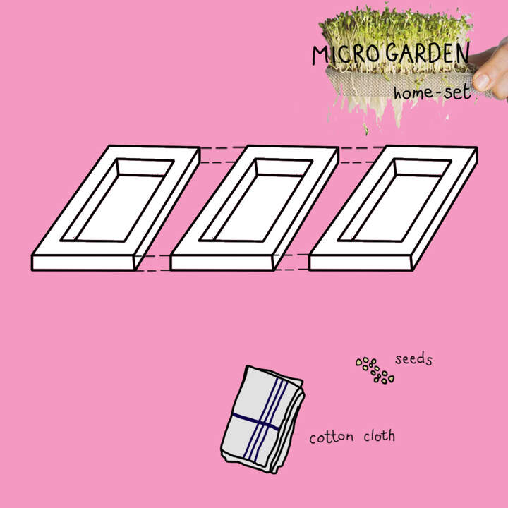
For the raster assignment I developed 3 drawings in PHOTOSHOP. I drew the first concept sketches for my chosen final project idea which I explain in more detail here. The main goal of the project is to design 1 main structure that can have minor adjustments and incorporations to accommodate 3 indoor-growing techniques. I have decided to start with a very simple structure and try to incorporate a bit of shape-complexity-design as I move on on the design process.
MICROGARDEN STRUCTURE:
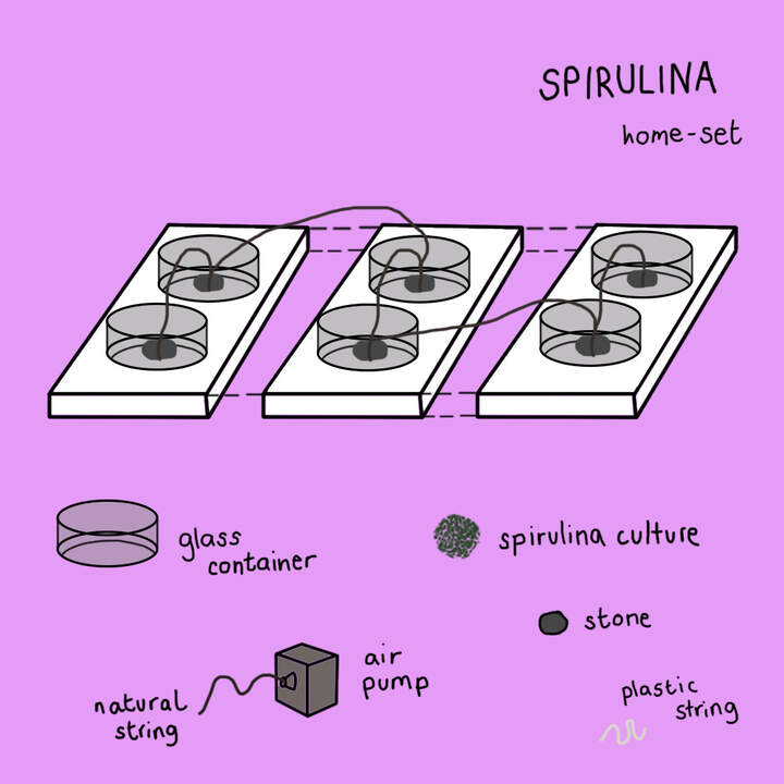
SPIRULINA STRUCTURE:
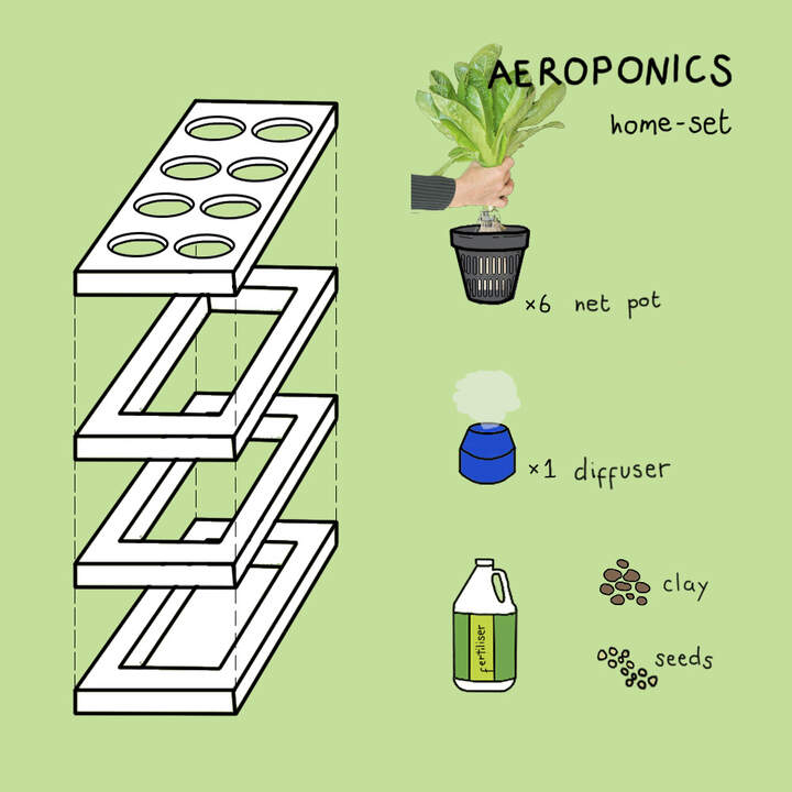
AEROPONIC STRUCTURE
Vector tools I tried out:
For the vector tools I am planning to show a bit of detail in the type of joints that could possibly join the pieces together within the project.
Inkscape: very recommended tool for parametric design.
I downloaded INKSCAPE for Mac users here
Playing with Illustrator
-
I placed the Photoshop sketch in Illustrator by pressing: COMMAND + SHIFT + P on an empty 920x1080 p canvas.
-
Turning this image into a template: double click on the layer icon > opens up a layer options box > turn on template mode > dims our image by 50% and locks it down > create new layer (this is where the outline of our sketch will be)
-
Draw 10p thickness with the Pen Tool the outline of the sketch.
-
If you press SHIFT - W you can use the width tool to modify the width of the lines you’ve drawn. I decided to try this out to give it more of a cartoon-look. As I say I am just trying out here.
-
Now we have the base of the structure completed lets add some colour to it (we want to add colour below the outline layer): create new layer > name it colour > select the outline > copy > paste it in back (in edit menu) go to the layers panel and drag the red square to the colour layer.
-
We need to separate the drawing into shapes with the shaper tool > select whole illustration in colour layer > go to shaper tool > and start adding colour.
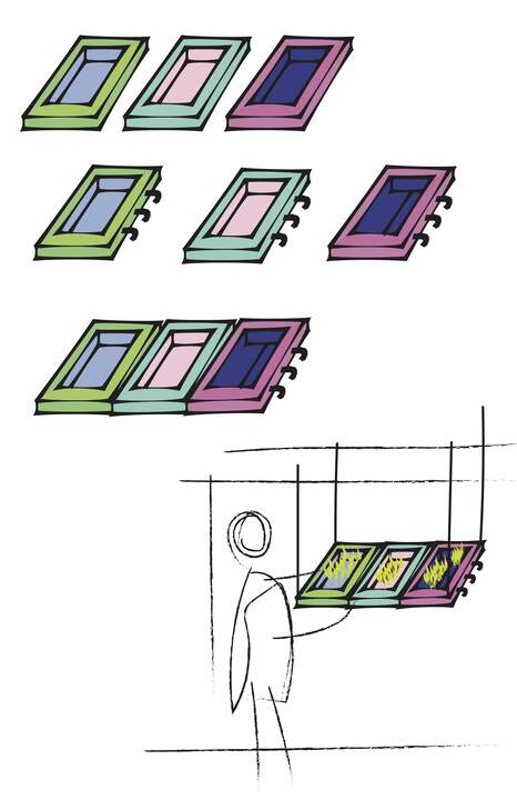
In this vector sketch I wanted to show how the structures could be joined together and then hanged from the ceiling:
FreeCAD
-
FREECAD: open source design tool, built around a very powerful engine
I started watching an intro video to FreecCAD.
I start by creating a Part Design > Choose create body > create sketch > select XY plane.
Now I have different drawing tools to start my sketch. I played around FreeCAD but I felt fusion 360 was a more understandable interface so I quickly switched program.
Step 3: Trying out 3D software
Fusion 360
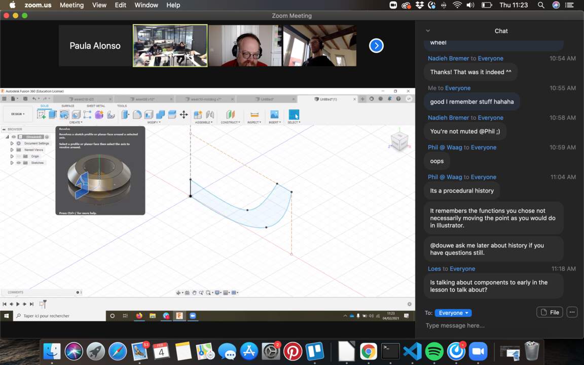
Tutorial 04.02.2021
I was given some basic tools to start with Fusion 360 as seen below:
First you create a sketch
Select a plane
You select a sketch shape (for example: rectangle…)
Snap your shape to a point or insert a value(mm) with keyboard. You can also modify the mm once the shape is done
Constraint = fixed
Parallel Constraints; for example in a rectangle, you can delete them and play around with the shape
You can also start sketching drawing lines: clicking/ add values
You have to create a closed form in order to give it volume
To decide dimensions, use the create dimensions button
Equal distance constraints > Click on two lines > Makes the line with equal values
Perpendicular constraint > Puts two lines perpendicular
Explore constraints to draw stuff with precise dimensions
Snapping
Moving/copy
When you click on Finish sketch it goes to 3D plain
To make volume: Use the extrude option by dragging the side you want to extrude or by giving it a numerical value. When you extrude you can create it as a new BODY and indicate which BODY you want to CUT.
Create different bodies to:
-
to print shapes separately (SAVE as STL for 3D printing)
-
to give different appearance (different materials) Body1 > Right click > Physical material > Choose materiality
To find out about the physical properties of your body, regarding materiality you go to Body1 > Right click > Properties > gives physical information (mass, weight, etc)
Parametric design:
What is parametric? It is like making a list of your own variables, which you can re-define at anytime and your model will change automatically. It allows you to quickly resize your model, by changing dimensions in a table. It avoids:
-
Scaling in the 3D printing software, which is not flexible and precise enough
-
Editing each line, one by one
-
Errors when changing lines in the model
This is a very simple and helpful video that helped me that understand the sense of parametric design: Parametric modeling in Fusion360 explained in 40 seconds + detailed tutorial with example
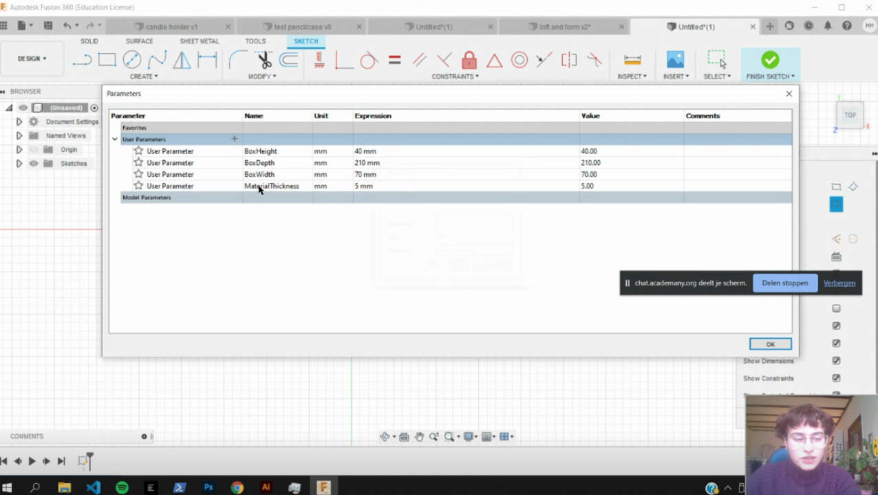
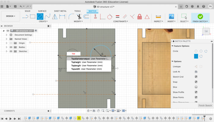
To insert parameters: Modify > Change Parameters > opens up like an excel sheet > “User Parameters +” > Press on the “+” Create a parameter like below by giving units + assigning a name for the parameter
Then you add the parameter to the shape by clicking a specific line > change number (mm) by clicking on the number box and typing the first letter of the name you assigned it > a list will appear > choose your preferred parameter > you have created a parameter! You can also create mathematical operations with parameters.
This works in case I don’t know the size of the object but I will eventually know so I create parameter variables that will automatically change it in the future, so I don’t have to re-draw all of the model again. It is for shapes that depend on the materials, specially the thickness
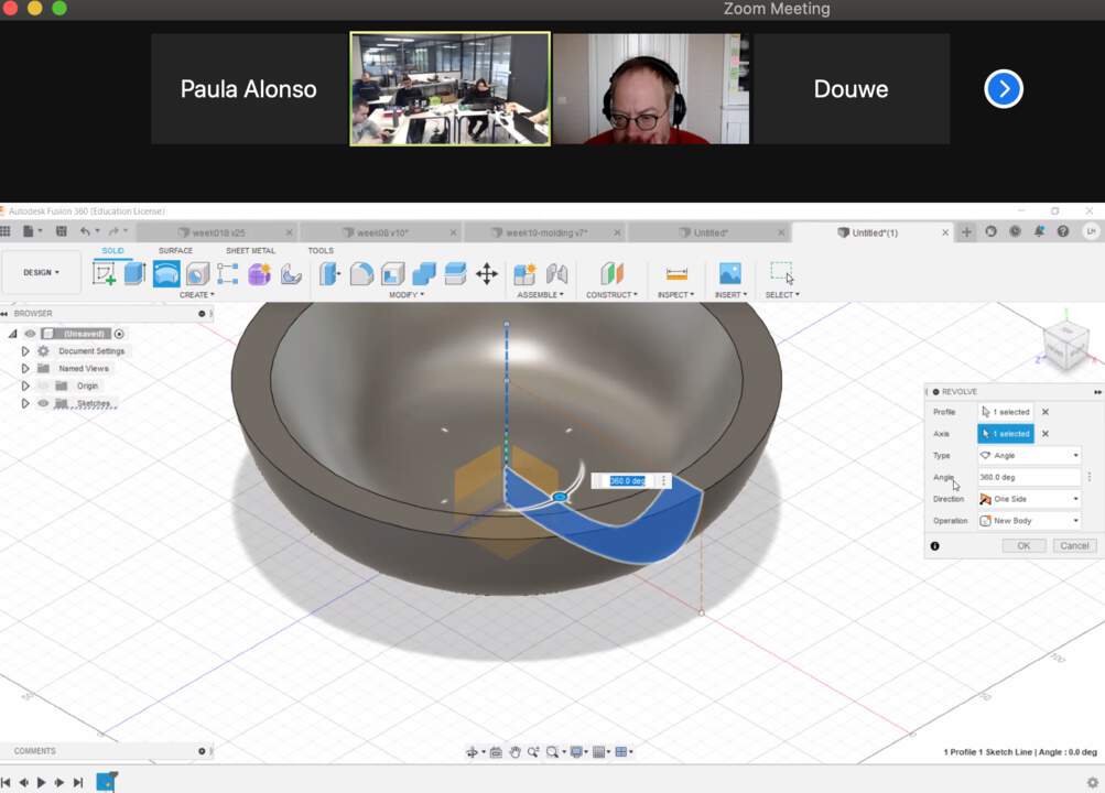
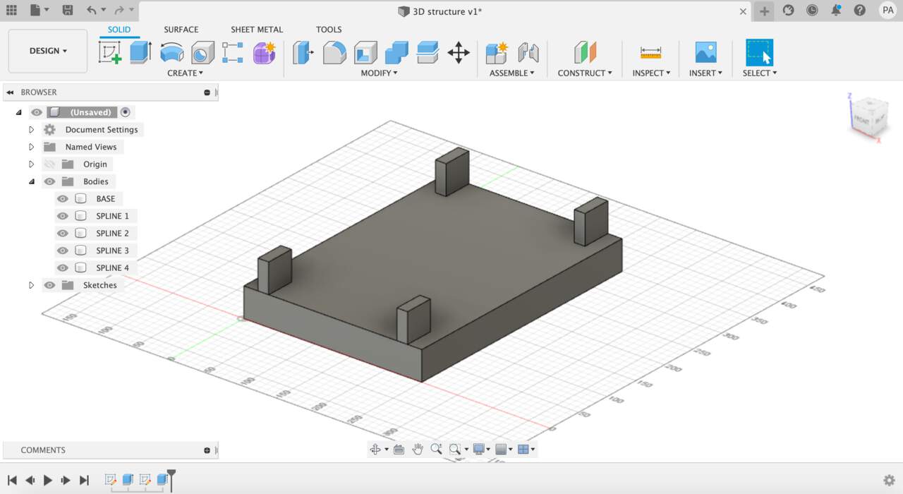
To create a bowl-shape + extrude it, you use the REVOLVE option Fit Point Spline > Draw Shape > Add parameters (like thickness) > Finish sketch > See shape in 3D dimension > Revolve > select axis (it will revolve around that axis) > choose angle Use the Revolve box shown below to try different ways of creating the shape
First step: draw a sketch and go to 3D mode:
Third step: revolve the sketch:
I can also create construction lines as a way to align my shape, it helps me build it
If I want to export my file in 2D I have to export it in DXF (laser cutting, vinyl,..)
INSERT TAB: for example I can insert an SVG file(SVG = scalable vector graphic, 2D) and work on it
For example: to draw a circle inside a rectangle, sketch mode, I can precise dimensions using the sketch dimensions tool to position the circle or I can use construction lines
BASICS INTRODUCTION TO FUSION 360
Tutorial 05.02.2021 Making a pencil case with Michelle
-
Define materials, dimensions in the beginning
-
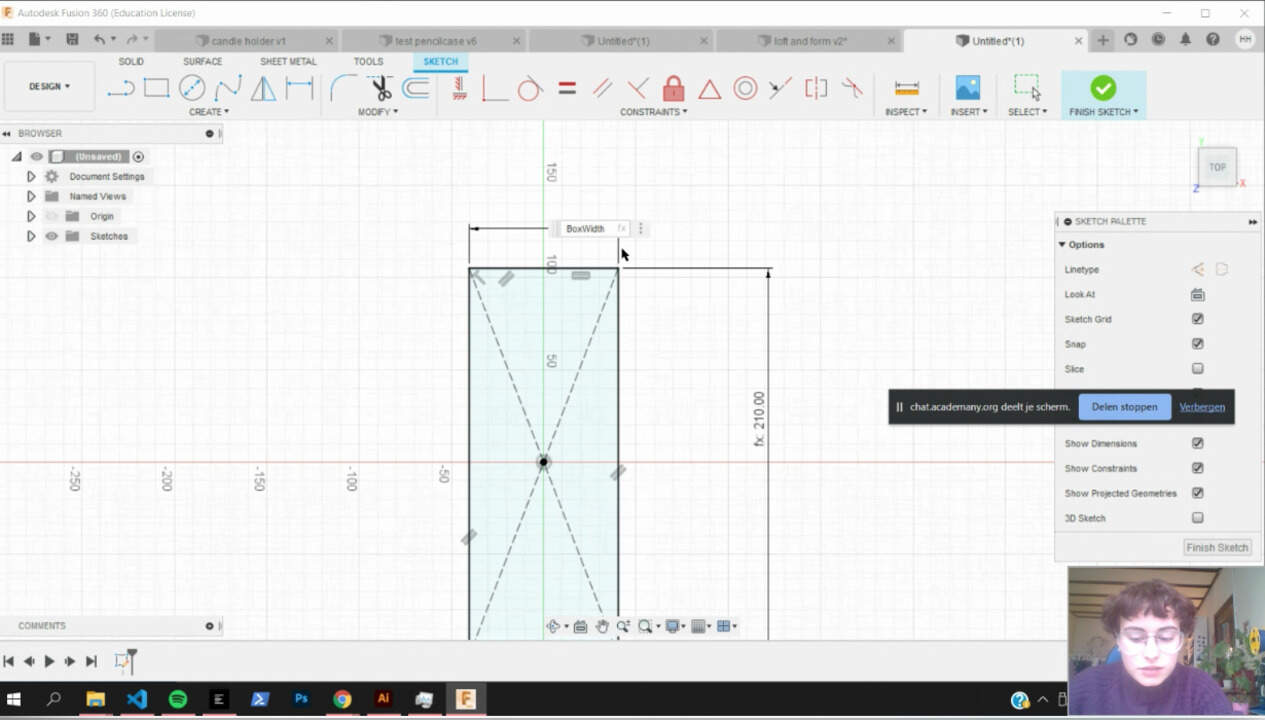
Sketch rectangle in sketch mode, start from the center.
-
Define your own parameters
-
Add parameters to rectangle
-
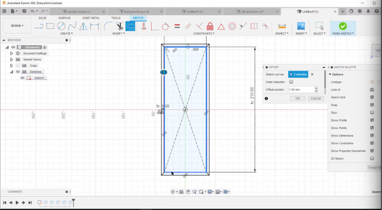
Create offset to create wall thickness + add parameter
-
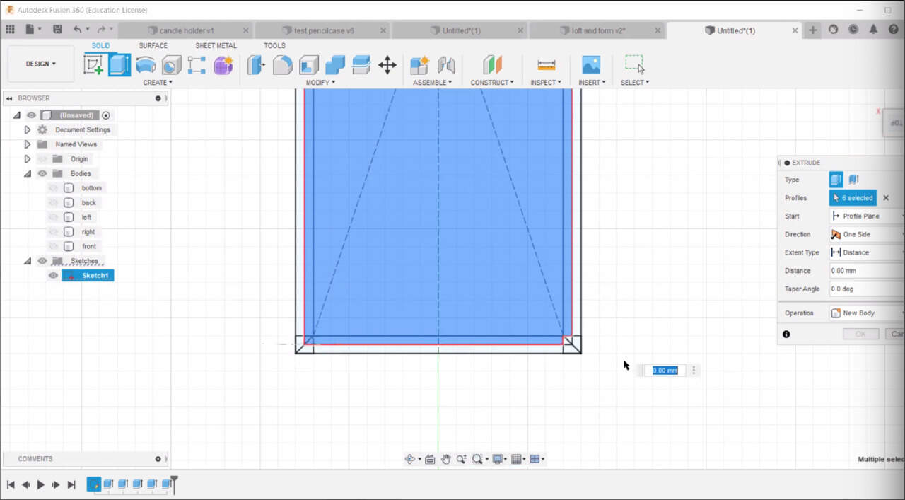
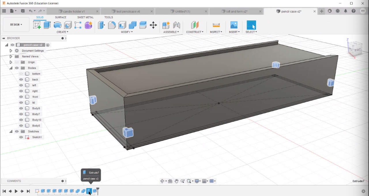
Extrude press E for extrude and extrude interior
-
Extrude exterior walls. Do wall by wall because if not it will join them all together. Make sure when you extrude it is make new body not join.
I can join the two pieces together (for 3d printing) For laser you want to do different pieces.
-
All walls done, except front one
-
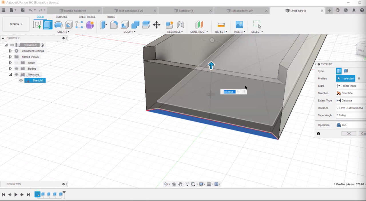
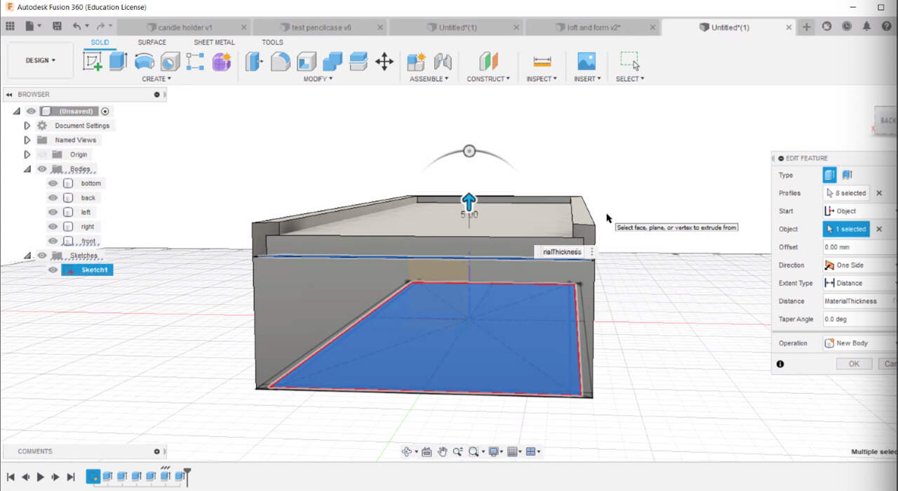
We add parameter of lid thickness
-
Select lid-wall when extruding you can also add a formula in the value box. For example; box height - 5mm - lidthickness
-
Select base > select right click > edit sketch > goes back to sketch mode, offset button > select inner lines(because outer lines are already offset and Fusion does not let you offset you again) > offset position: material thickness/2 (divided by 2). This is to create the lid dimensions
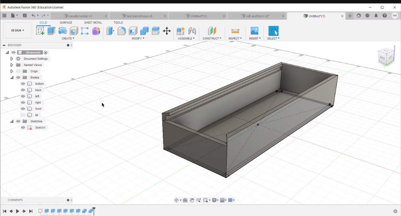
-
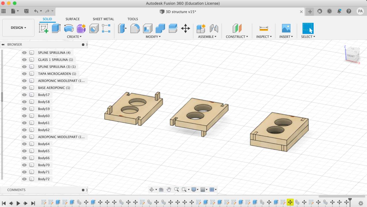
You have 5 bodies now and you can rename the bodies to know which one is which:
-
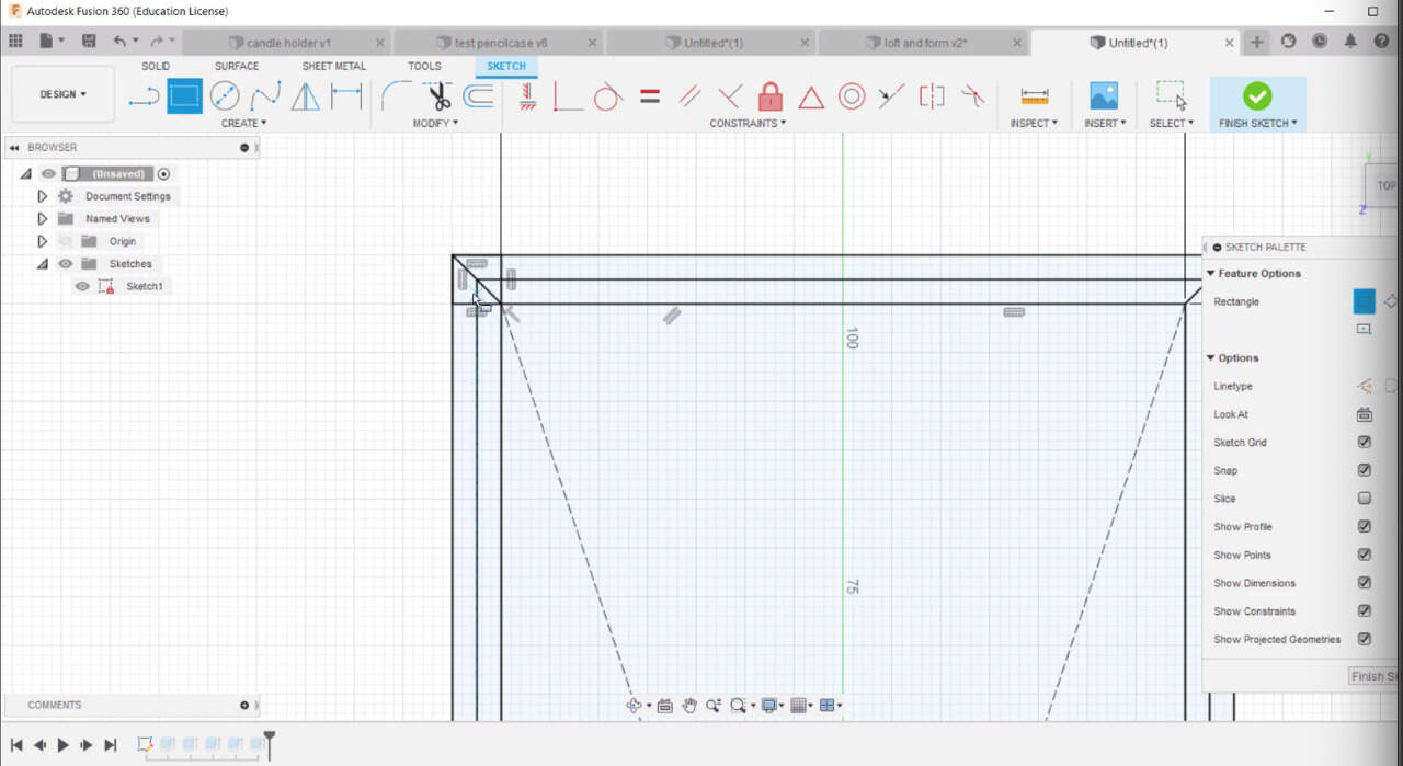
Create a two point rectangle > add parameter of material thickness on both sides > This is going to create a guideline to make the lid, we are missing a line to extrude after the lid
-
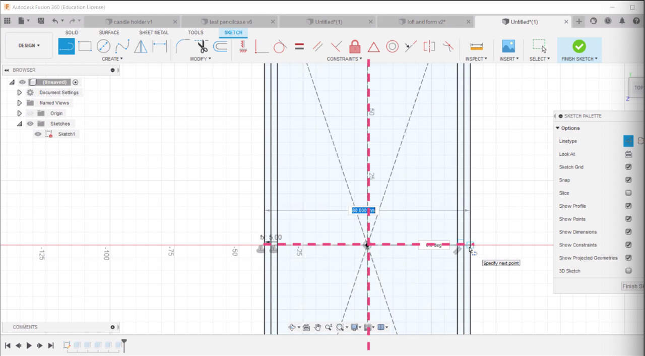
Create construction lines to use the mirror tool. > Mirror the box from left to right > Mirror the two boxes from top to button. > Now you have the boxes in the four corners.
-
Create lid: select 4 lines lid > put material thickness parameter > extrude
-
In extrude option box > Object extrude > select the face you want it to place it in. > it will place it there
-
Inspect > Sector analysis > To check your model is doing fine.
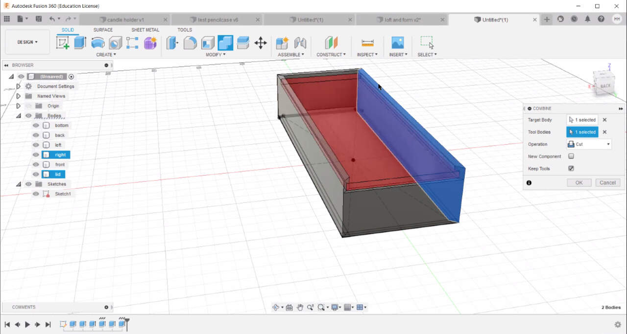
-
Cut out the lid from the walls: Combine tool > select lid and right wall > keep tools box ticked so it does not delete lid > Do the left side as well
-
Create little connection bits: lines to connect the wooden walls of the box:
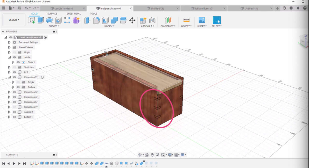
-
Hide bodies > you are left with sketch > select corners (see image) > extrude > add material thickness parameter > new body > extrude these pieces > cut out from walls
-
Create > Pattern > Pattern on path > Features > Extrusion timeline > select the 4 pieces > drag it up and repeats the action > quantity 2 > set up distance material thickness*3> ok
You can also do animations in Fusion 360
In Fusion 360 you have bodies and you have components (look at difference): Components: group of bodies, this allows you to assemble them to create animations. You start from bodies and then you create components from bodies to create animations, etc.
You can import components from other people if you’re working on things separately for one project.
A component can have bodies or it can also have components.
For this you:
-
Create> Create new component for all the box walls selected > Uncheck from bodies and activate buttons > Drag all your body walls into the component you just created.
-
Select lid and create a component from it
-
Select bits and drag them to a component folder called splines
-
Assemble > As-built joint > it asks for components (this is why we created) > select walls component and lid component > joint type (see options) > you can press animate.
-
A new folder created called joint (animation) it has an orange button (edit joint limit) > double click it > create maximum and minimum limit so you edit the movement of your components.
-
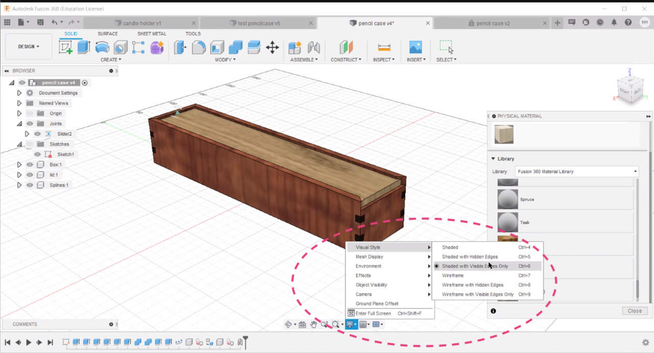
Add properties > Modify > Add materials > drag materials to components > gives preview of your material > scale pattern to make it look more realistic (play with numbers)
-
View options button:
Go to RENDER option to create an animation:
-
Make a base for your object> draw a big rectangle in sketch mode > select > surface > add material
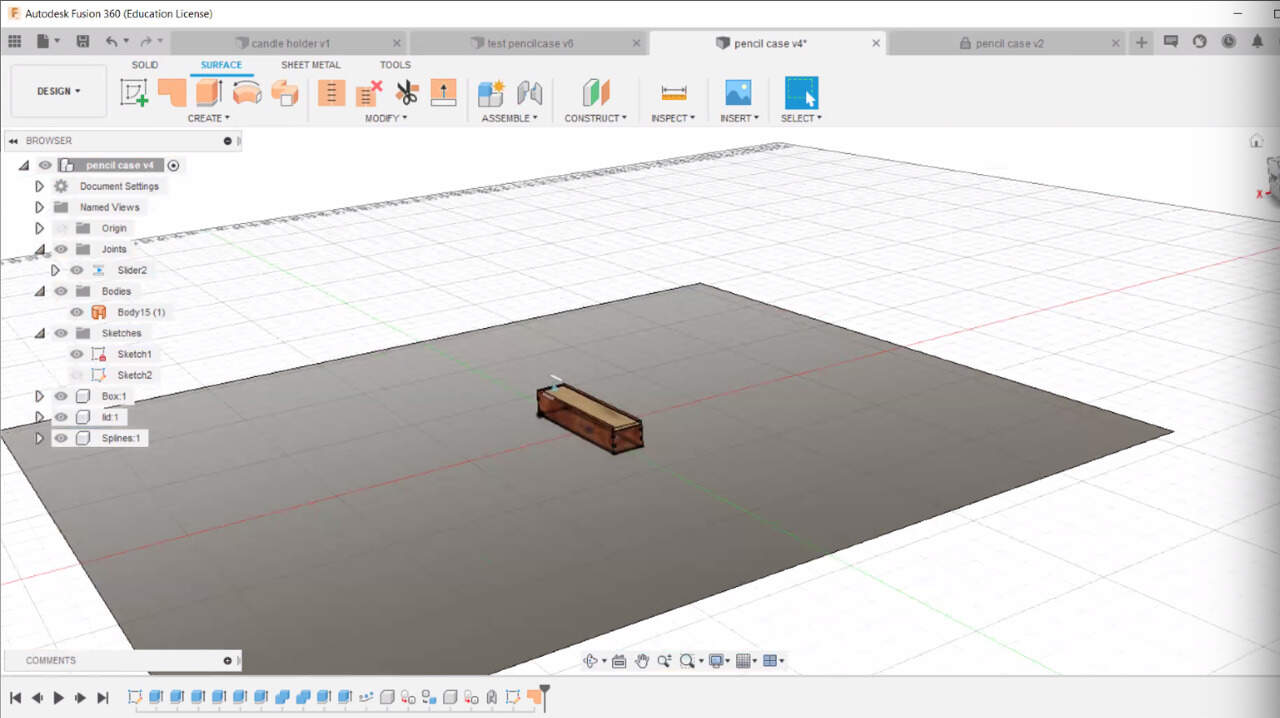
-
Now your box is standing in a beautiful table, without a grey background.
-
Edit scene settings(light, etc)
-
And then create an animation.
Version history with Fusion 360: - Everytime you save your file it creates a version number > add version description - Go to data panel > you can see your files and your version number > drop down v2 > you can see history > you can open up an old version >
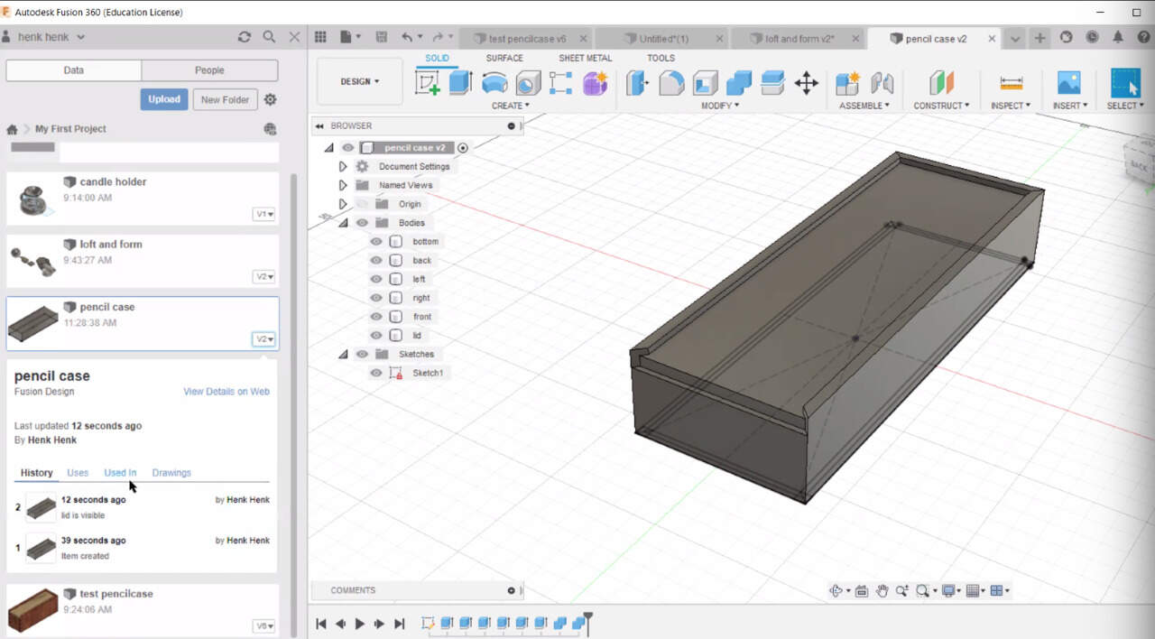
How to use Fusion 360 design timeline - I have realised I can use this tool to record the -how-I-made it for documentation. (Use play button, it walks through the whole process)
-
It is also very useful to see someone elses steps to get to the final piece, when downloading someone’s file.
-
Turn on component colour swatch under the timeline options, it will label all the features in the timeline by components.
-
Then if you go inspect > turn on component color cycling toggle > it will colour the components to help us relate what features relate to the components
-
If you click to activate a component you will see that only the features from that component will appear in the timeline
-
If you have long timelines you can also group them > holding cmd in Mac > select the features you want > right click > create group
More tricks on how to use timeline in Fusion 360 here
COMMON DOUBTS: How to insert a standard part into a Fusion 360 design from McMaster-Carr See answer here
Drawing out my model:
To explore 3D design I went for Fusion 360 because after several tutorials and workshops I decided it was the software that best fitted my needs and wills.
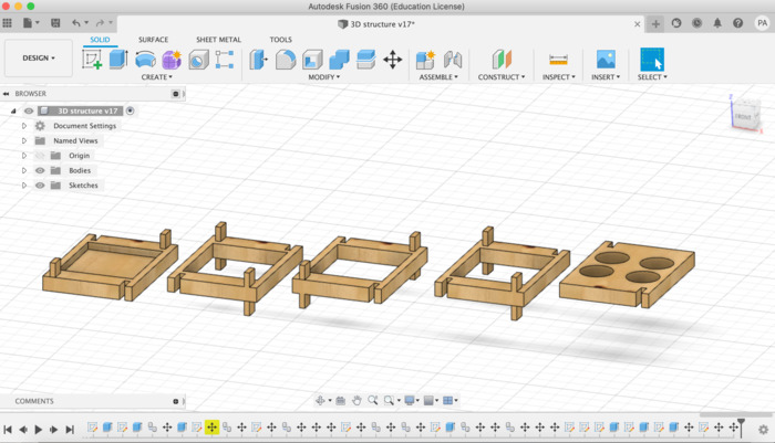
I developed a simple structure design for each system, trying to figure out how to assemble the pieces together with the minor changes. This is what took most of my time within the design process. I feel Fusion 360 has been a very intuitive and fun program to use and I will continue using it in the future!
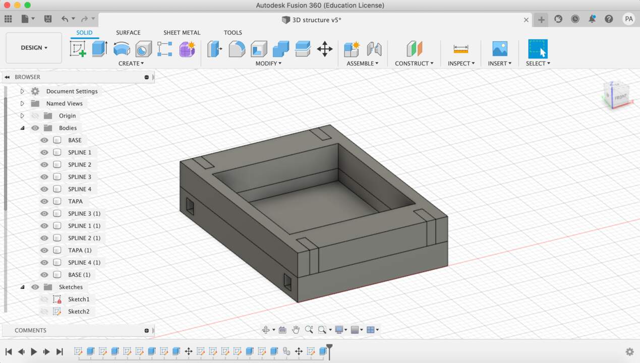
The structure is aiming to have different pieces assembled to each other. The idea that I worked out is that these piece would assemble in mirror (so it actually would be the same piece) but the top piece would have different cutouts so that the different indoor-growing techniques could be embraced.
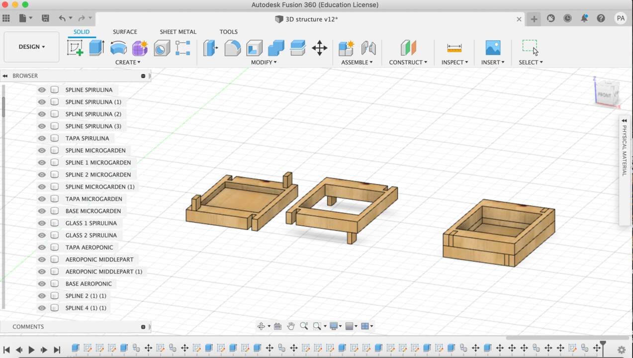
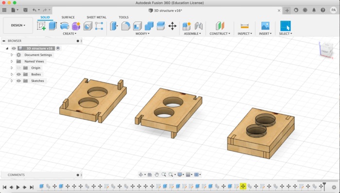
Trying out other material properties; in this case I put wood but I don’t think this will be the case as wood is not a suitable material with water.
MATERIAL PROPERTIES:
-
It has to be a light material
-
It has to be a non-toxic material
-
Ideally as natural/ recyled ad possible
-
Works well around water
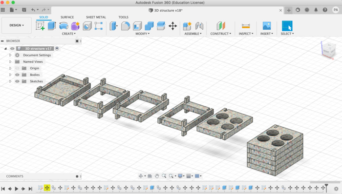
I learned how to create a new material from your computer here. The outcome was a recyled-plastic aeroponic structure:
What went wrong and how I solved it
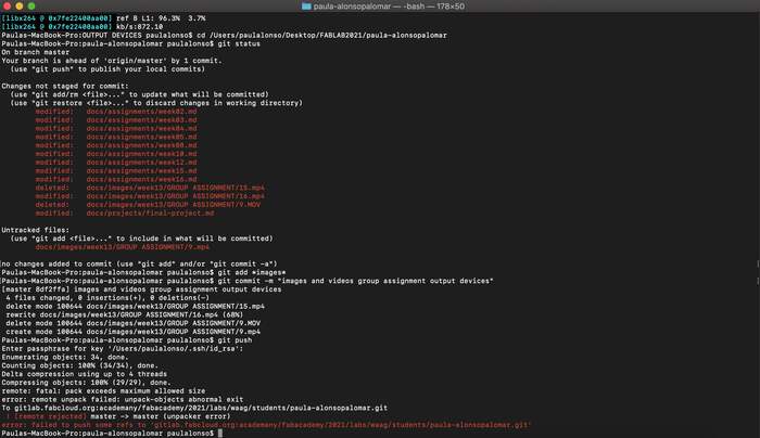
Issur 1: This week I messed it up with the git repository size (it was too big) The following error appeared, Henk helped me out.
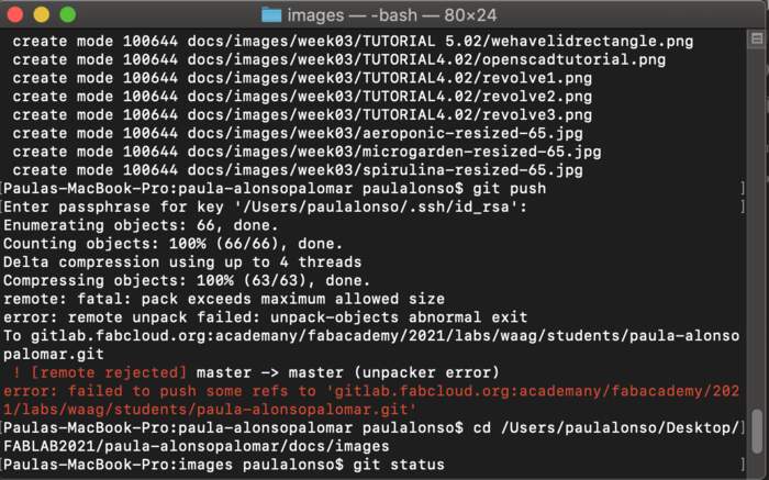
I started downloading NCDU. NCDU (NCurses Disk Usage) is an ncurses-based disk usage tool. It provides a disk usage summary in a TUI (text user interface), and also allows you to navigate between directories. I downloaded NCDU by typing in the terminal:
brew install ncdu
Then I went to my repository folder in the terminal and typed
ncdu
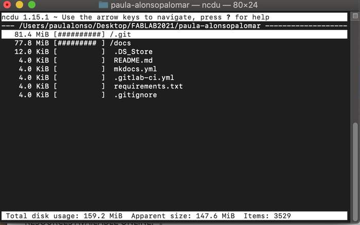
This is what you see:
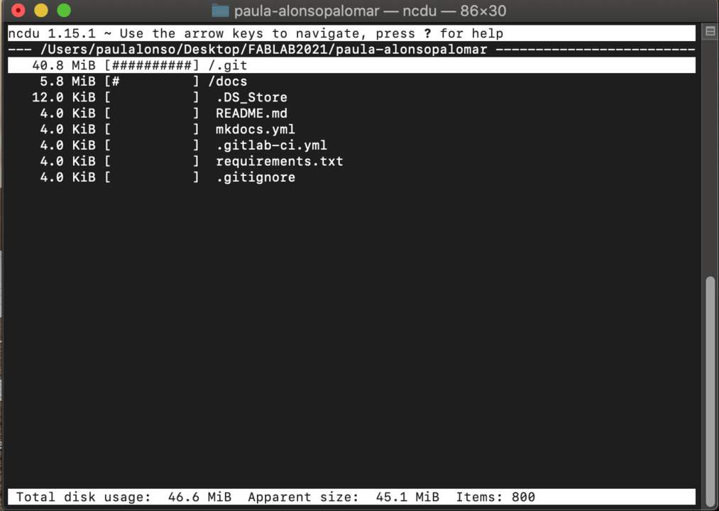
From here I learned that the history was too big because I had added and commited too many pictures and quite heavy so they then had become part of the tracked files (although they are not in my web server). I followed the very useful instructions of last years’ fab student Hyejin Ahn. The steps she took are in this Gitlab help link.
Before I tried this it is very important to make a copy of my repository folder in my computer
I first tried reducing the repository size through git filter-branch as explained here
This did not work so I had to delete my Git repository completely. Before I try this it is very important to make a copy of my repository folder in my computer I followed Hyejin Ahn steps again:
-
I deleted the .git directory and created a new Git repository.
-
I copied the .git/config file from the backup repository to the current repository. I discovered that in order to show hidden files in Mac you have to press Command +Shift +.(period) key and they will appear.
cp -r my_project my_project.bak # copies the directory to the new directory called my_project.bak. You have to run this command from the parent directory of your project, not inside of your project.
ls # see if my_project.bak directory exists
cd my_project # goes to your original repository
rm -rf .git # removes your Git repository
git init # starts a new Git repository
cp ../my_project.bak/.git/config ./.git/config # copies the original Git config from the backup directory to the current directory
git add . # adds everything
git commit -m "git init" # commits all files
git push origin master -f # force push to the master
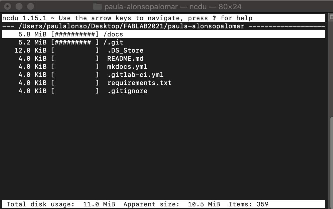
It worked! I went back to ncdu and the size had gone down:
In week 12 I messed up again with the git repository and I found an easier way to do this thanks to Loes she explains how she did it in week 4 of her documentation.
Issue 2: I ran out of time!
I was so concentrated in trying to develop a shape for the 3D-MODEL that I lost time to actually practice its modelling. In the end I decided that I am going to start with a simple structure and add complexity as the weeks pass by.
What I learned:
- To draw with parameters! I am still getting used to it but wow! what a difference it makes life so much easier.
Files to this week’s assignments:
- This is 3D.STL file for the design I made | 3D.stl