Week 11: Moulding and casting
Assignments:
-
Group assignment: Review the safety data sheets for each of your molding and casting materials. Make and compare test casts with each of them.
-
Individual assignment: Design a 3D mould around the stock and tooling that you’ll be using, mill it (rough cut + (at least) three-axis finish cut), and use it to cast parts.
What to learn:
-
Design appropriate objects within the limitations of 3 axis machining
-
Demonstrate workflows used in mould design, construction and casting
Have you?
-
Have you answered these questions?
-
Linked to the group assignment page
-
Reviewed the safety data sheets for each of your molding and casting materials, then made and compared test casts with each of them
-
Documented how you designed your 3D mould and created your rough and finish toolpaths for machining, including machine settings
-
Shown how you made your mould and cast the parts
-
Described problems and how you fixed them
-
Included your design files and ‘hero shot’ of the mould and the final object
DOUBT: Should I mill a mould for the group assignment? Answer: No, group assignment is for you to get familiar with the materials and the processes.
DOUBT: Should I read the MSDS and TDS this week? Answer: Yes, always. Document the main points.
DOUBT: I want to only make a wax mould, and cast something in it. Is that acceptable? Answer: Only after you learn and go through the 3 step process. To break the rules, you have to master the rules.
DOUBT: What does 3-axis milling mean? Answer: You should have smooth tilted or curved surfaces instead of “steps” towards axis Z.
DOUBT: Can I 3D print the mold? Can I do a lasercut? Answer: No, for this assignment you must mill the mould using a CNC milling machine. After fulfilling the requirements, please go ahead and experiment other techniques for fabricating moulds.
What is moulding and casting?
This instructables project explains a lot of terms of moulding and casting.
Mold making resources:
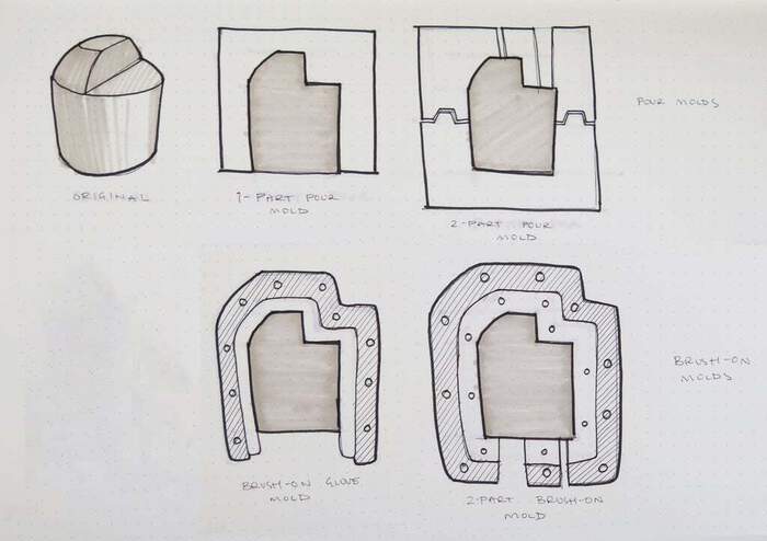
Types of molds:
-
Pour mold: mold made by pour silicone over an original inside of a containing box
-
1-part pour mold (block mold) - a pour mold with only one side (simplest type of mold)
-
2-part pour mold - a pour mold with two or more halves and registration keys to align the parts
-
Brush-on mold - a mold made by brushing on thin layers of silicone to build up a skin that is then encased in a rigid mother mold to give structure while casting
-
Glove mold - A brush-on mold that does not require a parting line (sometimes uses a small slit)
-
2-part brush-on mold - A brush-on mold that is split into two or more parts
-
Lifecasting - Mold made of a living human
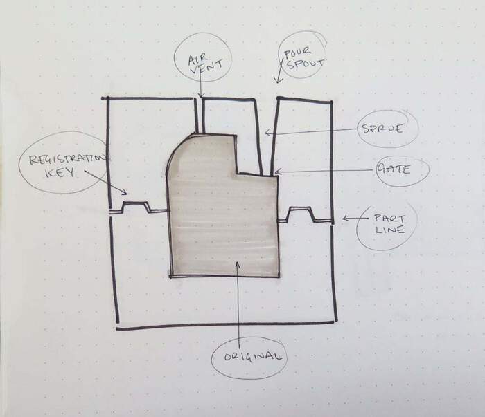
Vocabulary(helpful terms):
-
mold: overall system of parts used to replicate parts
-
casting (cast): replicated part made of final material
-
flashing (flash): extra unwanted material left on casting as a result of casting process. Usually along part line
-
original (prototype/part): What is being replicated
-
box: container for pour molds (mold walls)
-
mother mold (shell): hard exterior covering to give brush-on molds structure while casting
-
runner (sprue): hole that casting material is poured into
-
key: registration points for lining up sides of multiple part molds and holding them in place
-
part (split) line: borders between two sides of multiple part molds
-
mold release: release agent applied to original and mold to facilitate release of original and casting from mold
-
undercut: area of original that overhangs and can create difficulties casting
-
lifecast: mold made with a living original. Usually a person.
-
air vent: passage for air to escape mold chamber during casting process helps avoid trapped air in casting
-
rotational casting: rotating mold while casting to create hollow final model
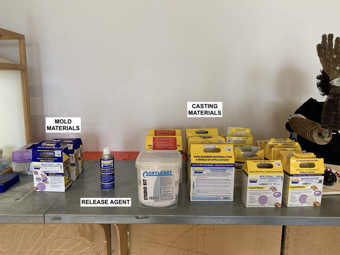
Types of materials + machines we have
-
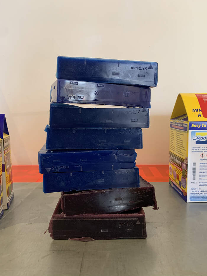
Wax blocks: here we will mill our mold negative with the CNC:
-
Molding: molding materials we will pour over the CNC model
-
Casting: casting materials we will pour inside our molds to create the final piece.
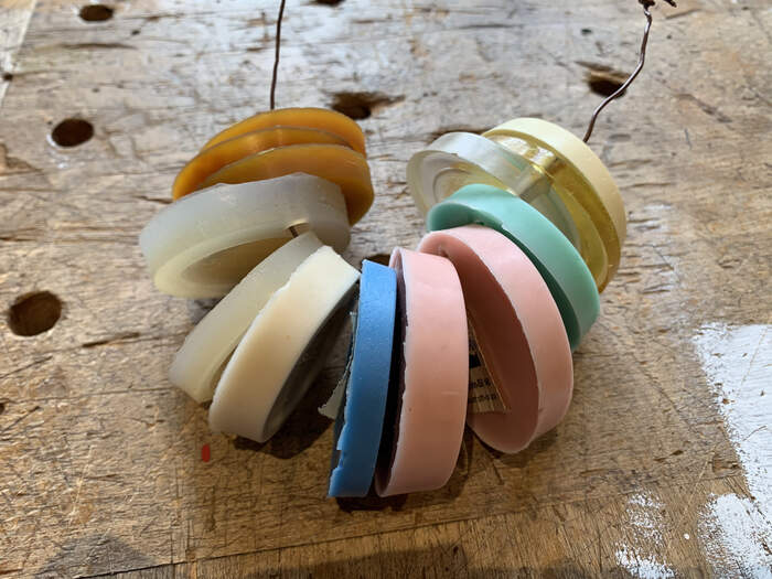
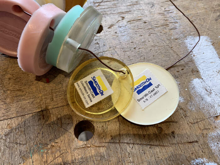
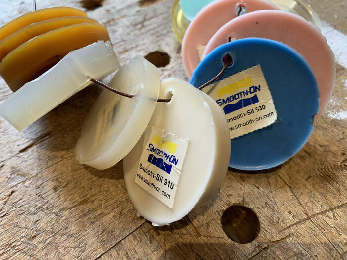
-
These are the samples from the materials above:
-
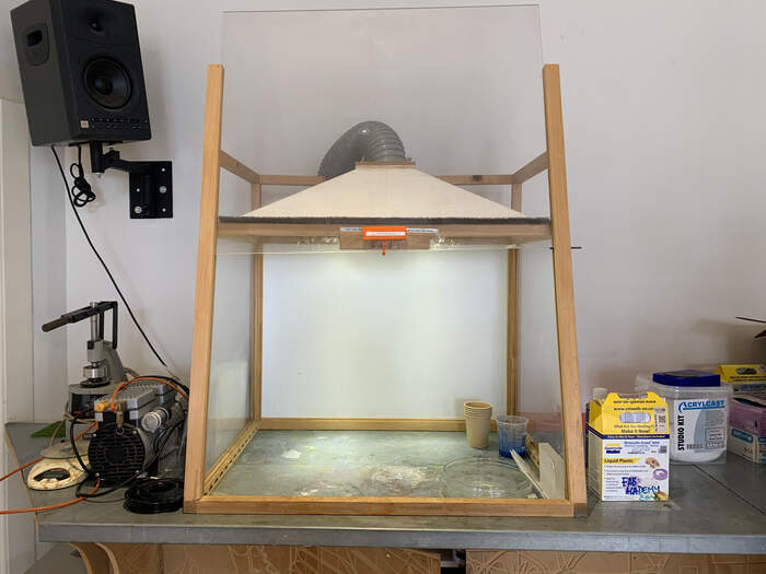
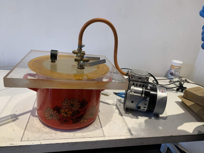
Vacuum pot: to take out as much air bubbles from materials as possible, photos below.
-
Extractor: depending on the material properties we will have to use it or not.
-
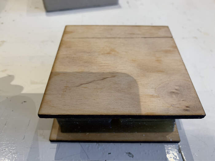
You can also make some laser-cut wood pieces to press the two molds together:
Group assignment:
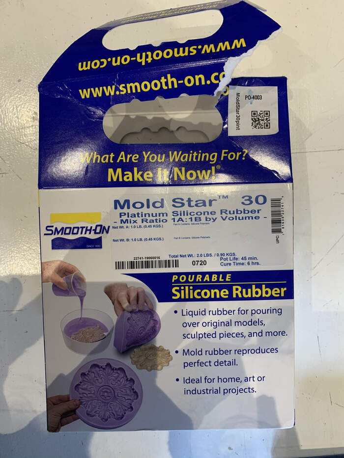
We will make a test with Silicone Rubber Mold Star 30 Platinum Silicone Rubber Mix Ratio 1A:1B by Volume. This is a liquid rubber for pouring over original models, sculpted pieces and more. This mold rubber reproduces perfect details. It is ideal for home, art or industrial projects.
-
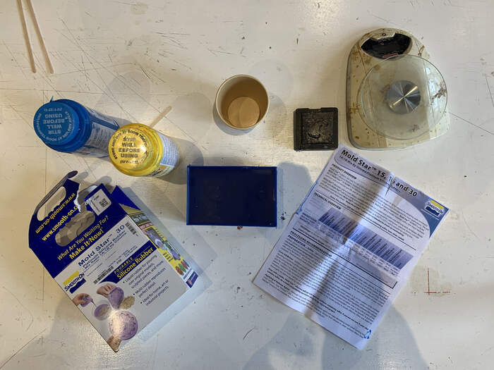
Our setup for the group assignment:
-
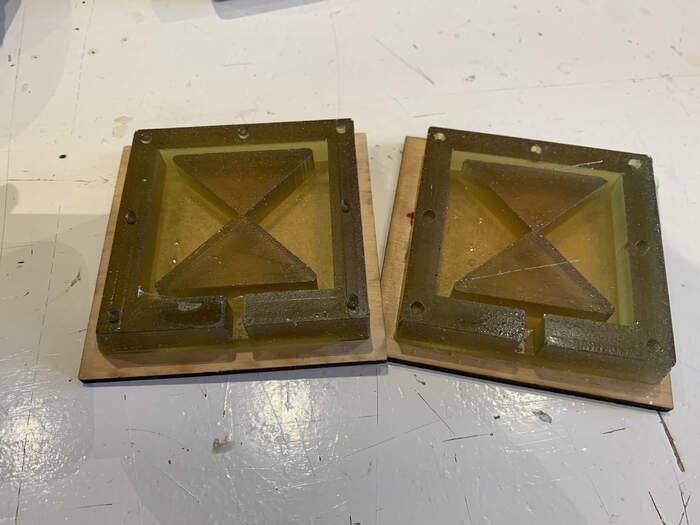
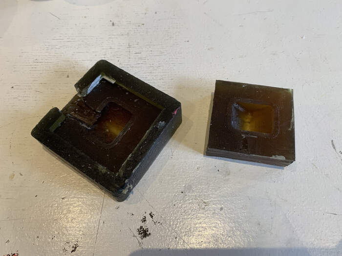
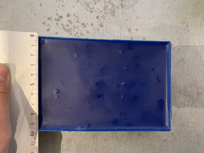
This is the mould we found at the lab which we will use for the group assignment:
-
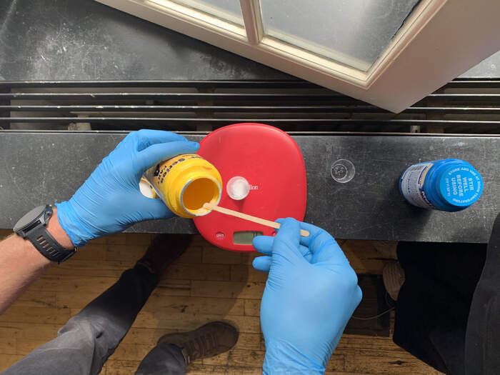
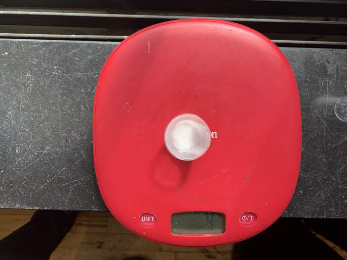
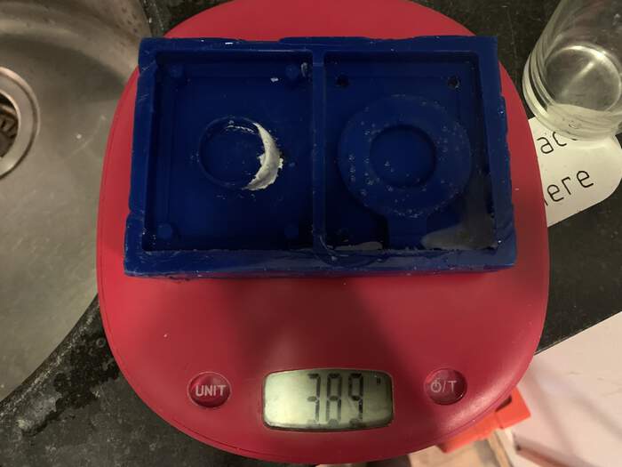
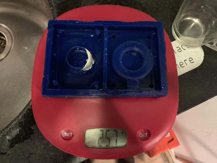
We have to mix two components, we mostly do it in paper cups o plexi cups, depending on the material, and we only do it with small amounts. To know the exact amount we fill the mold with water, then put the water in a cup and weigh it to know the exact amount of material in gr we need and not waste material. First we measure the mould without water.
-
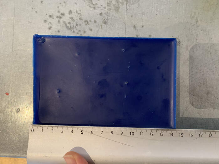
Then we pour the water inside the mould and measure it:
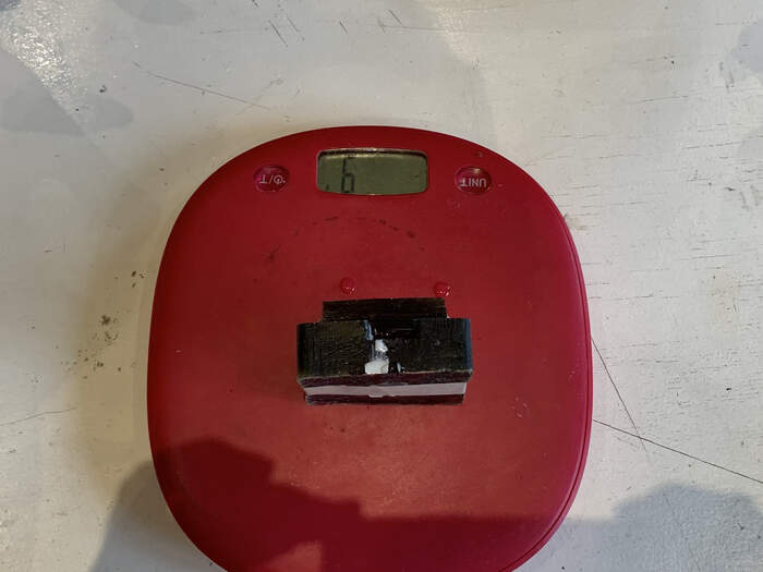
-
The measure of ml is 8 so we will need 8 grams of the measure.
-
We read the product overview which we can also find here
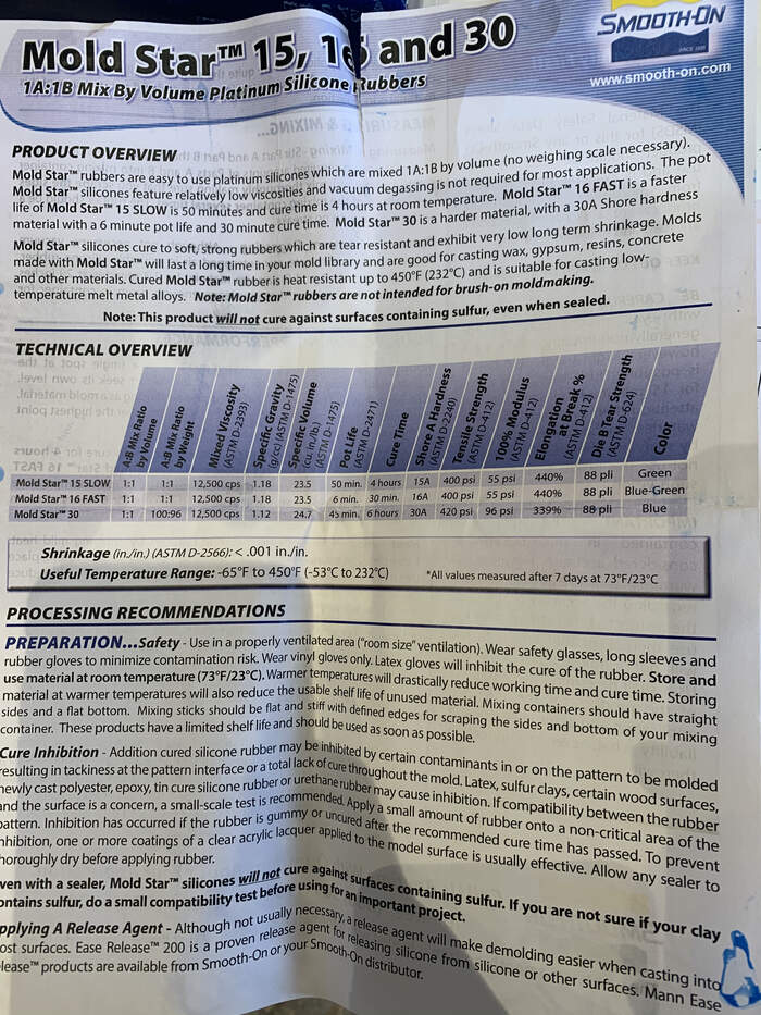
Some important things to remember when reading the product overview:
-
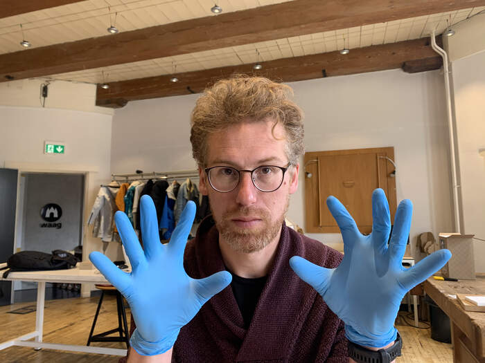
We need to wear vinyl gloves because latex will inhibit the cure of the rubber we will be using nitrile gloves
-
When mixing stir before dispensing, and place the uniform color with no streaks
-
Optional vacuum degassing: helps eliminate entrapped air in pourable silicone rubber, after mixing parts A and B, vacuum material for 2-3 minutes at 29 inches of mercury. (fixed measurement of pressure at the lab)
-
The pouring and mixing is 1:1 proportions
-
We will have to pour it in a single spot at the lowest point of the containment field, with a uniform flow to help minimize entrapped air.
-
We will pout it a little bit tilt so the liquid can find all the spots (Neil’s recommendation)
-
The curing takes up to 6 hours.
-
The time to demold can be reduced by applying mild heat…
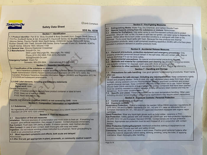
We also read the safety sheet instructions which can also be found here
-
Point 2: This material is apparently quite harmless
-
Point 4: No inhalation, eye contact or skin contact. If any skin contact wash with soap and water. No ingestion
-
Point 5: carbon dioxide foam (normal extinguisher) if fire, no hazards arising from the substance or mixture
-
Point 6: when accidental release: clean up with dilute ammonia solution
-
Point 7: keep in temperature and wash hands after use
-
Point 8: wear gloves and glasses
-
Point 9: physical and chemical properties
-
It does not say specifically we need to do it under the extractor but as Henk says it is always good to do it at least with the window open. As this product is quite harmless we will do it with the window open.
-
We first pour 1:1, 4gr:4gr of each mixing liquid:
-
We then mix well as we read in the product overview instructions, remember to mix it very gentle to avoid bubbles.
-
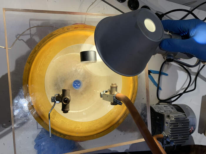
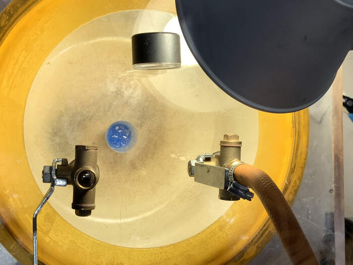
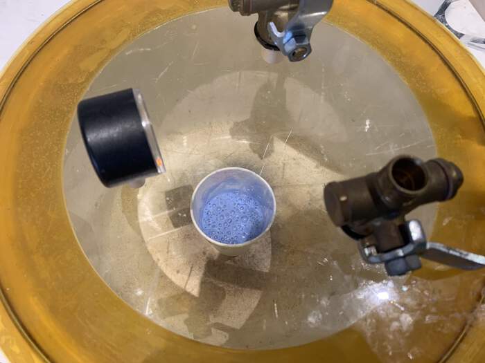
We then used the vacuum pot at the lab to take the maximum air bubbles as possible from the mix, as indicated in the instructions this should only take between 2-3 minutes.
-
We then poured it very carefully in the mould (which we had put some tape on to to keep in place):
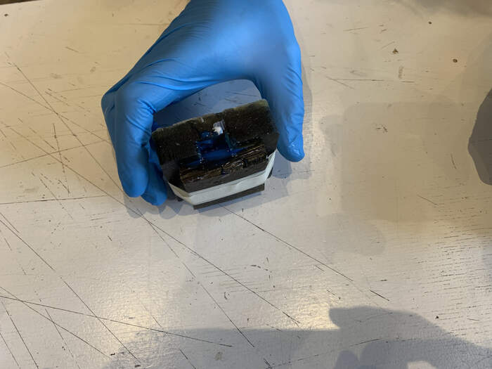
-
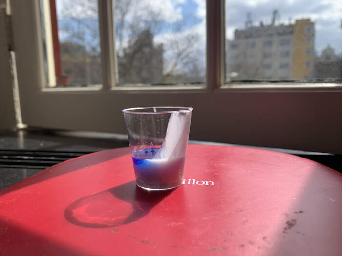
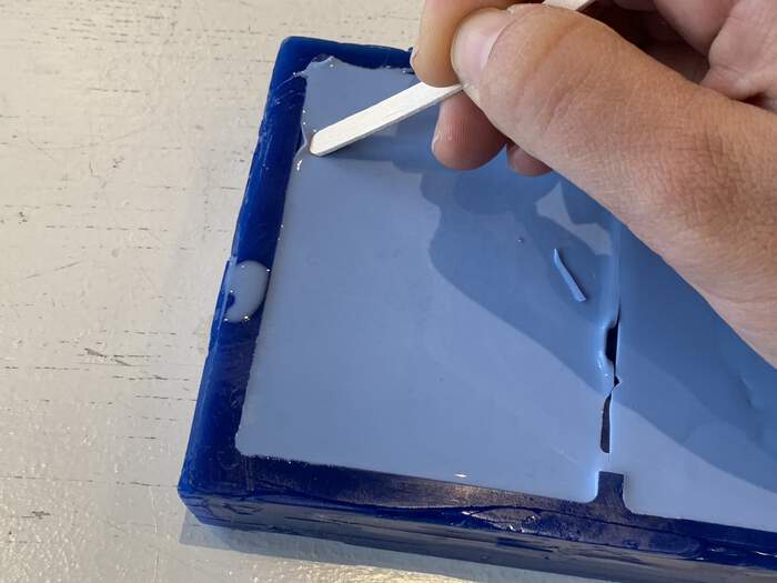
This is a small video of the whole process of the group assignment:
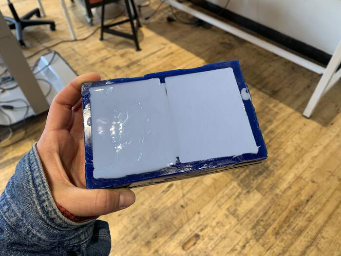
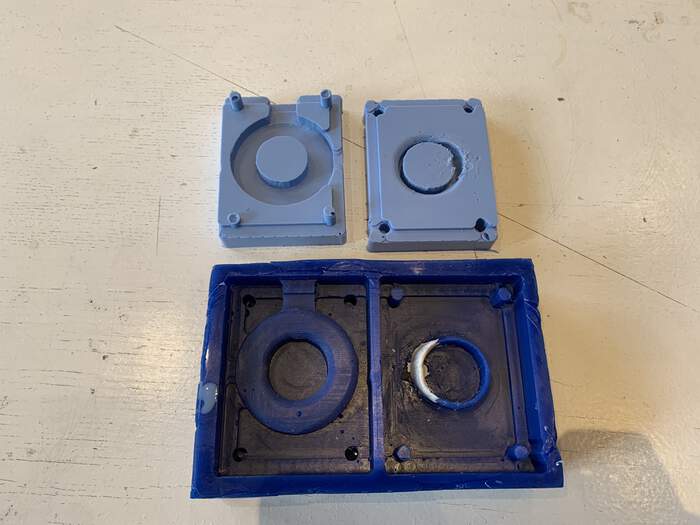
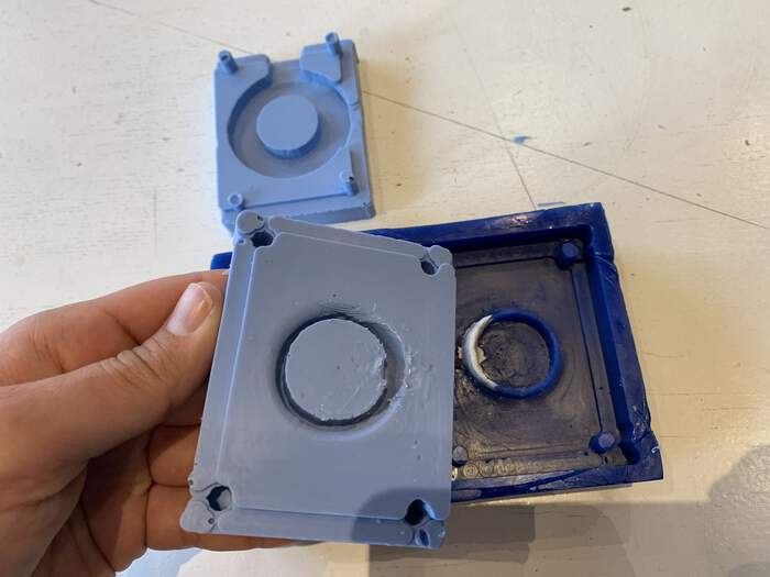
- This is the final result when we opened the mould:
Individual assignment:
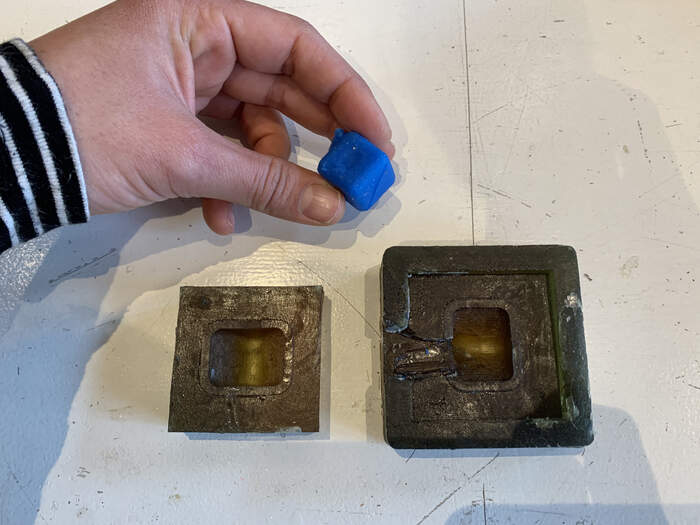
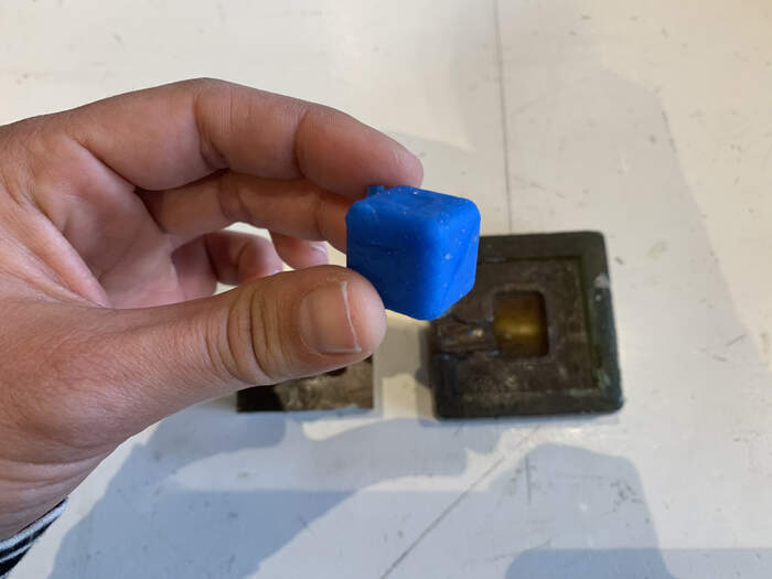
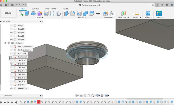
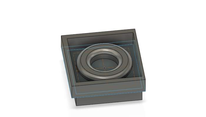
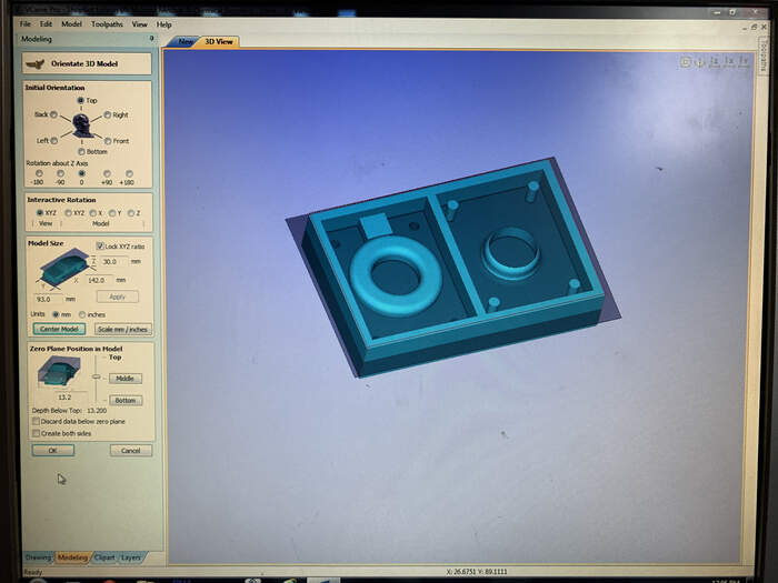
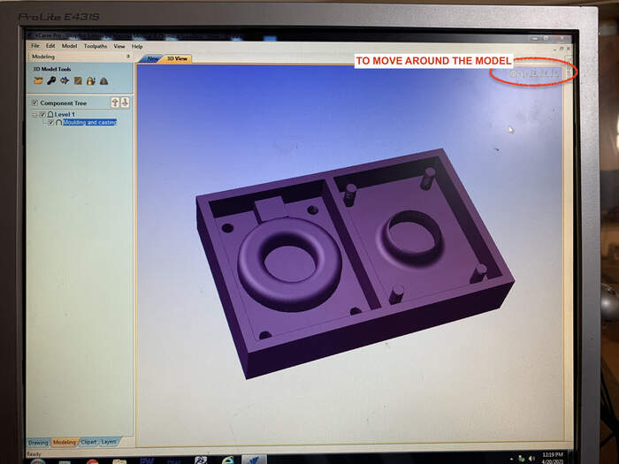
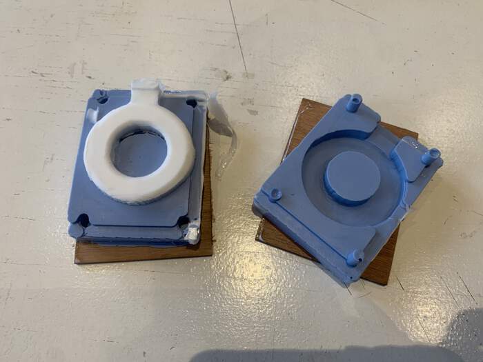
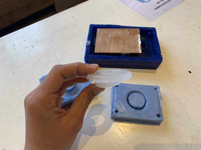
For this week we should make a 3 way mold because a 2 way mold is too simple. This is an example of a 3 way mold explained by Henk:
-
For this assignment we will use the Shopbot 3D milling to cutout our block of wax. This is the blue part from the image above. It is a negative of the mold we will want to cast.
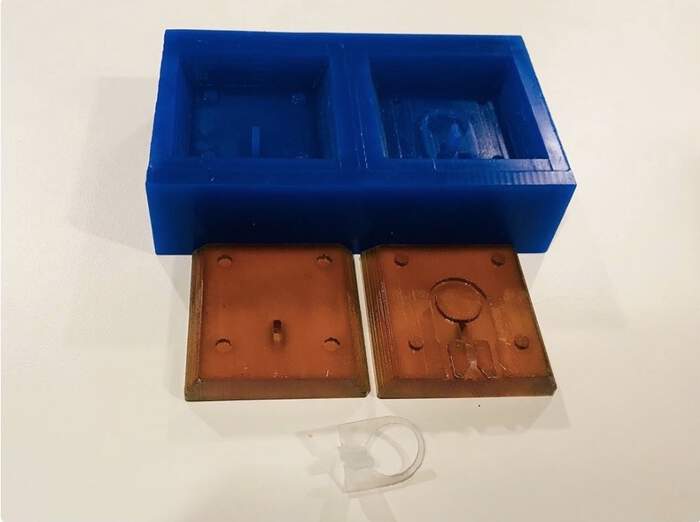
-
The brown part is the result after casting to get a rubber/flexible mold. We have to use registers for a perfect fit of the 2 sides of the mold. We also have to use an opening to pour in the substance for the final cast.
-
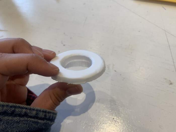
The transparent part is the casted ring (final piece).
Following Harm’s tips from last year, the big differences from CNC-make something big are:
-
We have to think in 3D
-
We will fix the material using Wood and double side tape
-
Import an STL
-
Use the 3D view in VCarve
-
Make two toolpaths (rough & finish)
-
Use low spindle speed (6000)
-
Don’t use the vacuum
-
Use higher travel speed: spindle speed 6000, Feed rate (both): 50 mm/sec
The lessons learned he talks about are:
-
The material is not flat. Look what the difference is between the highest point and the lowest. Use this as an offset.
-
I had the material on the side of the bed. The wax fell of the table. Put the material in the middle of the table (so save wax and cleaning time)
-
The finish is really rough. I used the ball nose mill. Don’t use a ball nose Mill to finish for flat surfaces
-
Make sure the mill is long enough to go into the deepest part the material. I checked all dimensions. My Model is only 9 mm high,the deepest part is 6 mm from the top. So the head will not touch the wax. I let the Mill stick out 15 mm to make sure It could never be a problem.
Some other tips from Henk before starting:
-
We have to design in 3D, making a negative of our positive.
-
We have to remember to read the datasheet of the material, specially the safety datasheet.
-
When we mix it mix it very gentle to avoid bubbles.
-
Try to avoid using epoxy because in composite week we will use it a lot, this week it is better to explore other materials.
-
Erwin also shared this very interesting (and free) book on food stiffening with tons of recipes and explaining why you want to use what kind of gelling agent.
Inspiration
-
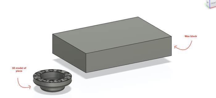
I had many ideas of the type of things I could do this week (plant pots, sunglasses, tiles, bowls, etc) but due to the small piece of wax we had to mill I had to forget most of them. This is the size of the wax we have for our project: 14.4cm x 9.6cm x 3cm
-
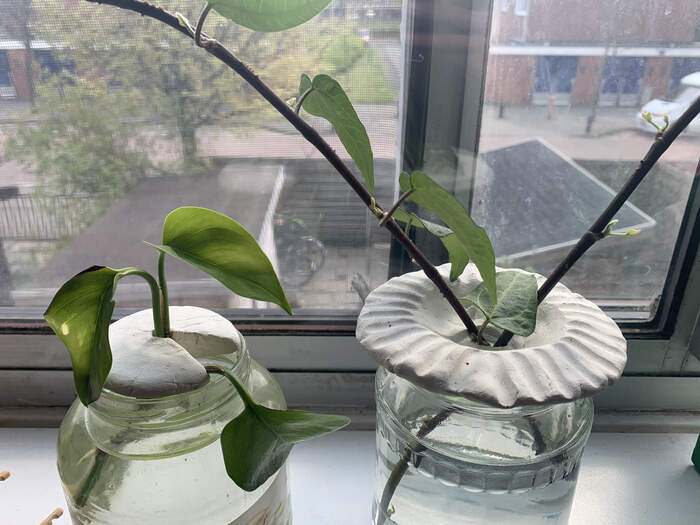
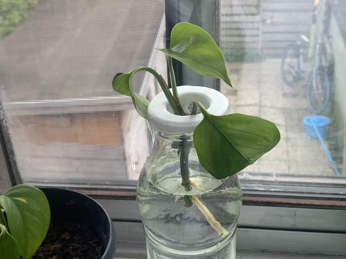
I then though why not make a small simple structure to hold my cuttings in place. I had already done this with clay in the past:
-
But this way if I had a mould I would just have to reproduce it one time over and over and use them in different types of glass bottles. It was a simple design and Henk said we should keep it simple and small so I went for this idea.
Designing in Fusion360
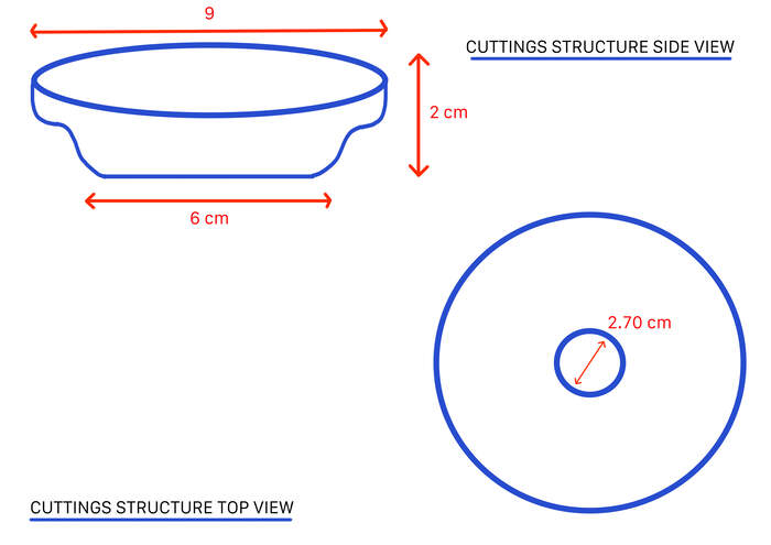
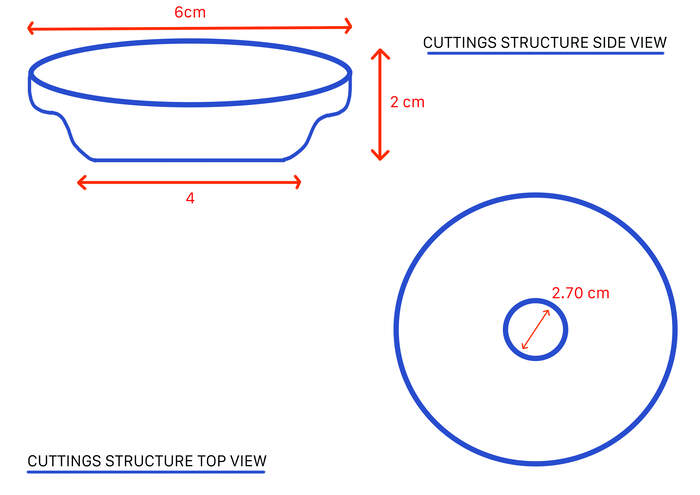
I first did a small sketch with dimensions:
After some researching I knew that in Fusion360 I had to do the following steps:
-
Create the 3D model of the piece
-
Create a mold from it (add registers for perfect fit, an opening to pur substance in and add ir vents).
-
Create the wax shape from the mold
-
Save it as an .stl
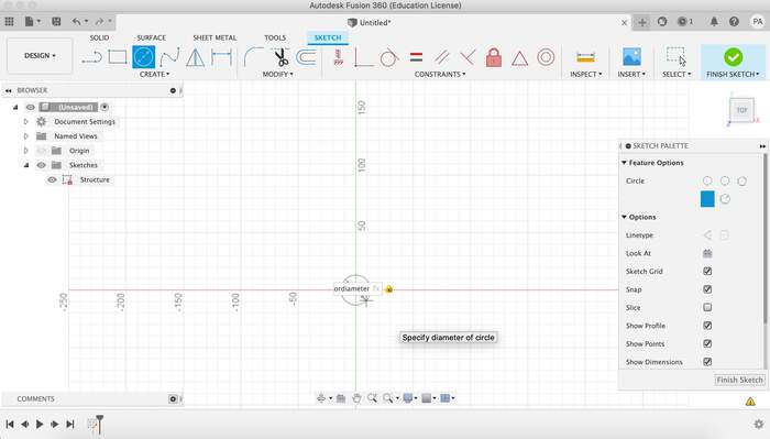
For this I first opened Fusion 360:
-
I realised that the width: 9cm was too big because I had to take into account the width of the wax wall and also the wall of the inner mold wall. I looked into how much space other student gave. If the wax block was 14.4cm x 9.6cm x 3cm I would give my 3D model piece a width of 56 mm. I changed my dimensions:
-
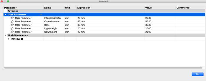
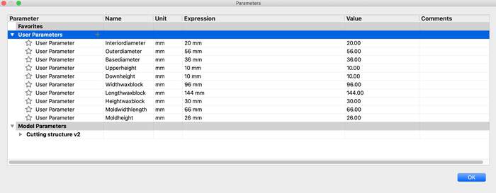
I first gave different parameters to the model:
-
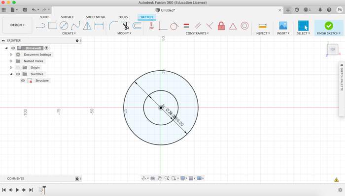
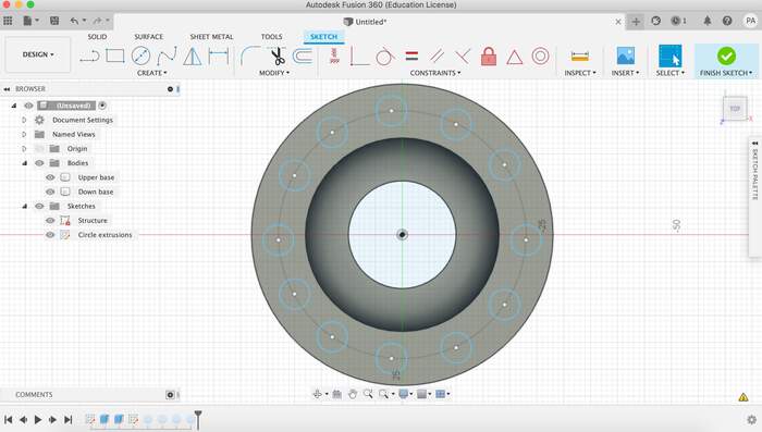
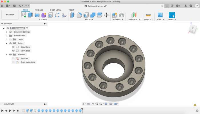
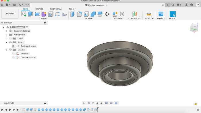
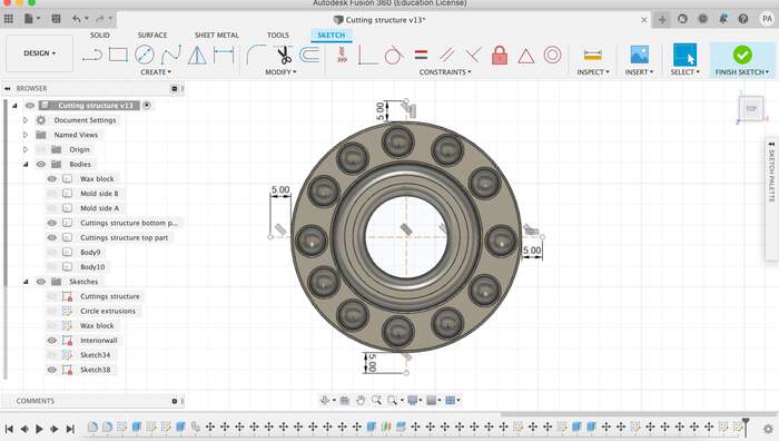
From this I started to sketch the different diameters and extruding them:
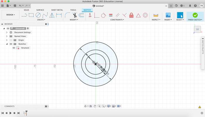
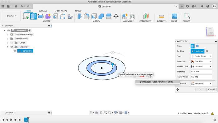
-
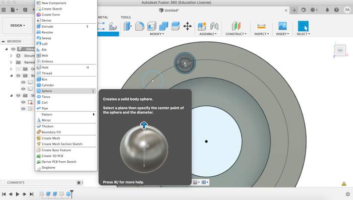
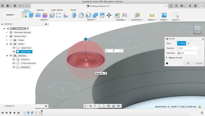
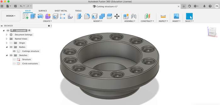
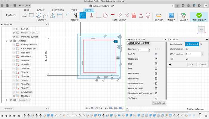
I wanted to sketch some concave spheres within the top layer just for decorative purposes, to understand better how to work with 3D negative-positive modelling and also to see how the CNC 3D milling worked like with small holes. For this I offset a line to create a middle point from where to sketch the circles. In these circles I cutted spheres out from the shape.
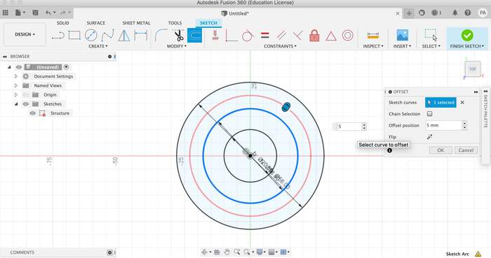
-
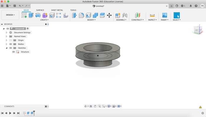
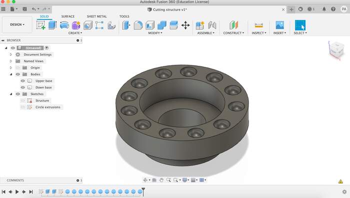
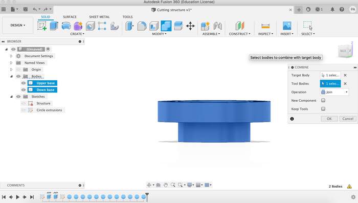
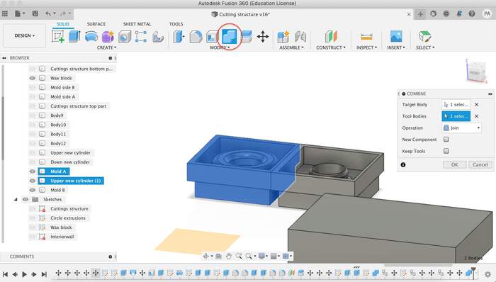
I then combined both bodies to create one.
-
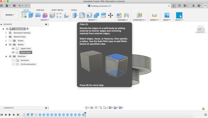
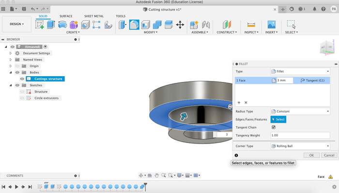
After this I used the fillet tool to give the whole structure a more smooth look:
-
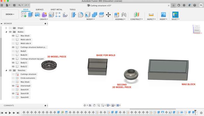
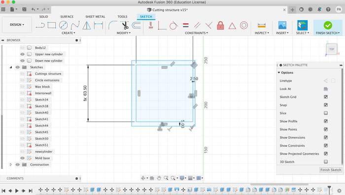
Now I drew the wax block as another body with the following dimensions (creating parameters within these just in case I had to modify them when milling and actually re-measuring the piece, as all of the pieces are quite irregular).
-
After reading a bunch of other students work I decided to create a wax block boundary of 5mm:
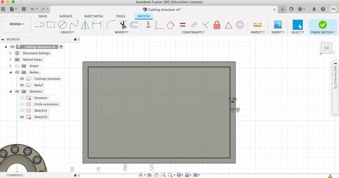
-
This would leave me with an interior space of 134mm, if I divided this by 2 (as I was going to make two parts) it would give me 67mm for each side of the mold. The two molds had to have some distance between them so I took 1mm from both and distanced them by 2mm, leaving each side to measure 65mm. As the width of the cutting structure was 56mm this would leave me with 10mm for both mold walls on the side(5mm each):
-
The height of the total cuttings structure was 20mm and as the total height of the wax block was 30mm and I was doing two molds that would fit together with registers, each mold would need 10mm height. I gave each mold a bottom thickness of 10mm leaving 10mm between the mold and the bottom of the wax block.
-
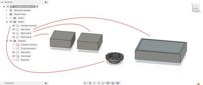
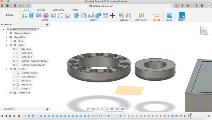
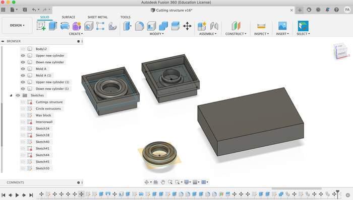
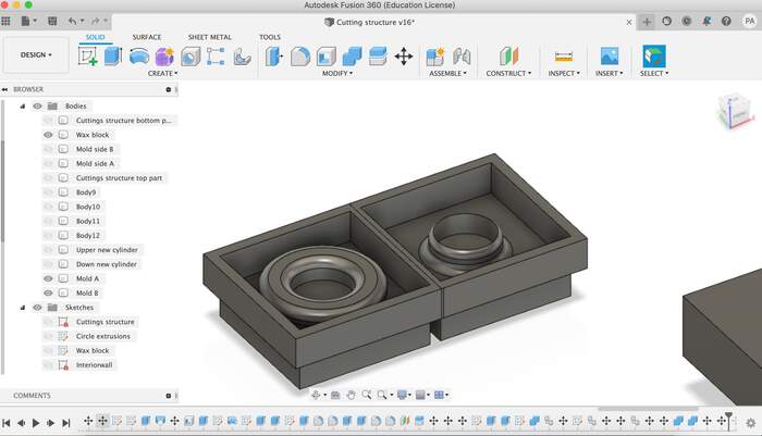
This would be the mold of the 3D piece model (I now have to do the negative of this piece):
-
I then realised this was wrong and this was what would come out from the mold of the wax block. I had to make the piece the other way around.
-
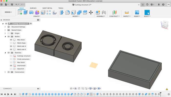
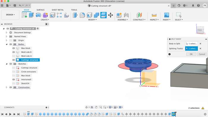
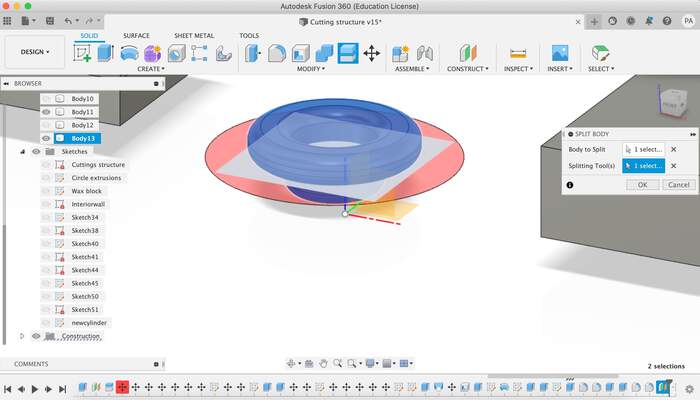
I cut my 3D piece in half and rotated the bottom part to make them both fix one to each other (when I had the mold):
-
I came to the studio and realised my block of wax was slightly smaller: 14.2cm x 9.3cm x 3cm. I calculated the shape with 5mm margin between the walls and realised the shape was too big:
-
I thought of making a different shape as the circles I wanted would no longer with the new smaller shape:
-
I started another even more simple shape:
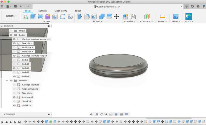
-
I cut my piece in half and rotate the bottom again:
-
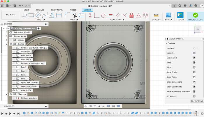
I drew a border around my shape to make sure the 5mm mill would pass through:
-
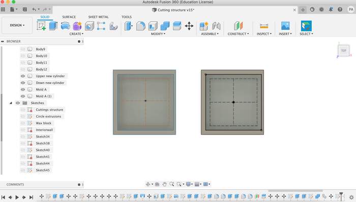
I also drew a center point so I would align both halves from the same middle spot:
-
I combined the pieces together:
-
Make sure to follow Nadieh’s advice: Be sure to make the distance between the outer wall of the wax block and where you’ll mill not smaller than ±8-10mm, you’ll never zero-align the mill perfectly I just gave it a separation of 5mm (too precise).
-
Finally I have my shape; Phillip adviced me that an air vent was not needed so I just did the registration points (6mm holes not 5mm as VCarve Pro does not read exact 5mm holes exactly) and a vent to pour the material:
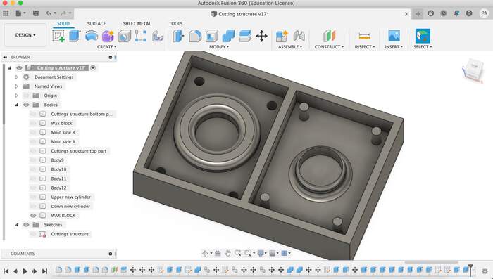
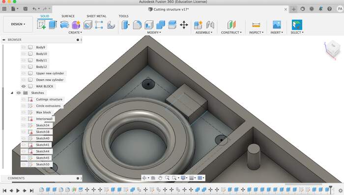
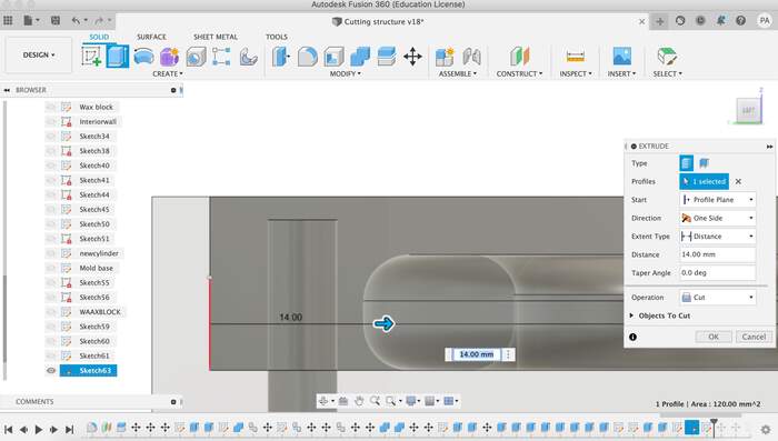
-
Saved the file as an .stl
Creating the toolpaths in VCarvePro
-
For 3D milling you have to create 2 toolpaths: roughing (left) and finishing (right)
-
Open VCarve Pro
-
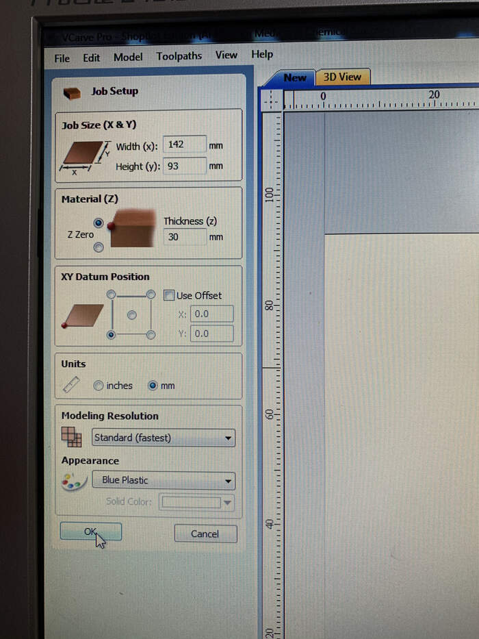
Create a new job
-
Set dimensions for block of wax > Ok (Start in Fusion360 with the same dimension block as you are going to use wax.) material block has to be bigger than the model, this is shown in V-Carve with the red line.
-
Import component > 3D model (file extension is .stl) (third option in menu)
-
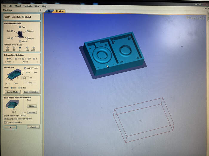
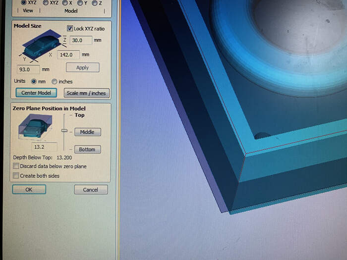
In the left hand menu, press center model:
-
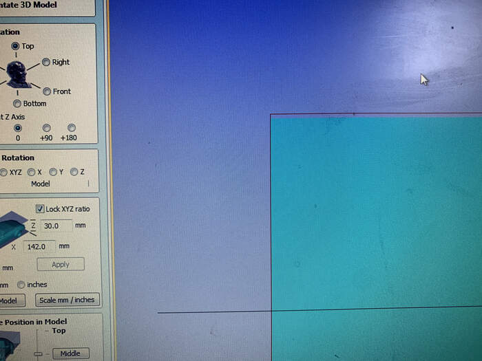
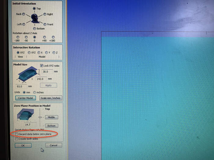
In the zero plane position make sure you place the red box slightly above the 3D model (wax blocl) > Press Ok.
-
Make sure you uncheck the following box:
-
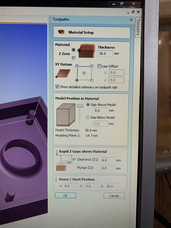
In toolpaths on the right > set > you setup the material setup:
-
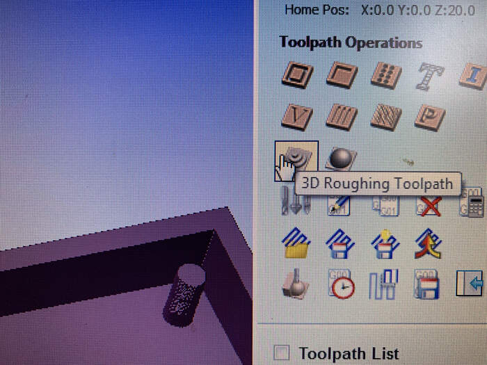
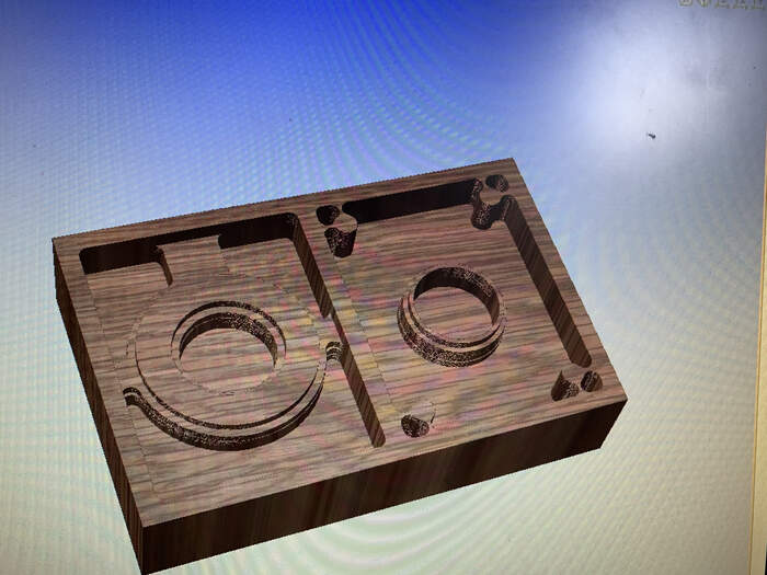
Create new toolpath > First we do the 3D roughing toolpath:
-
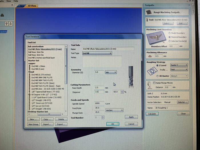
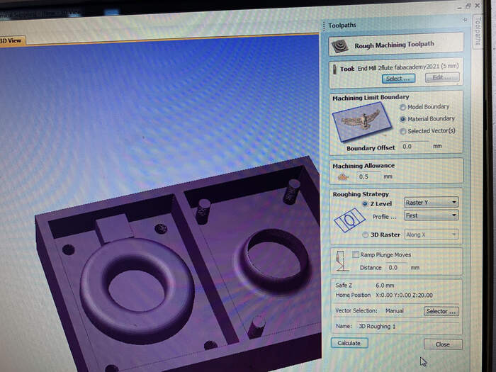
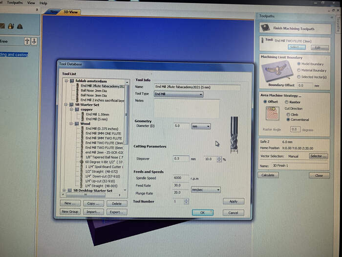
First we will select the tool: which is a 2 flute 5mm diameter tool, spindle speed(how fast it turns) 6000, feed rate(how fast it moves from side to side) 30, plunge rate: 20:
-
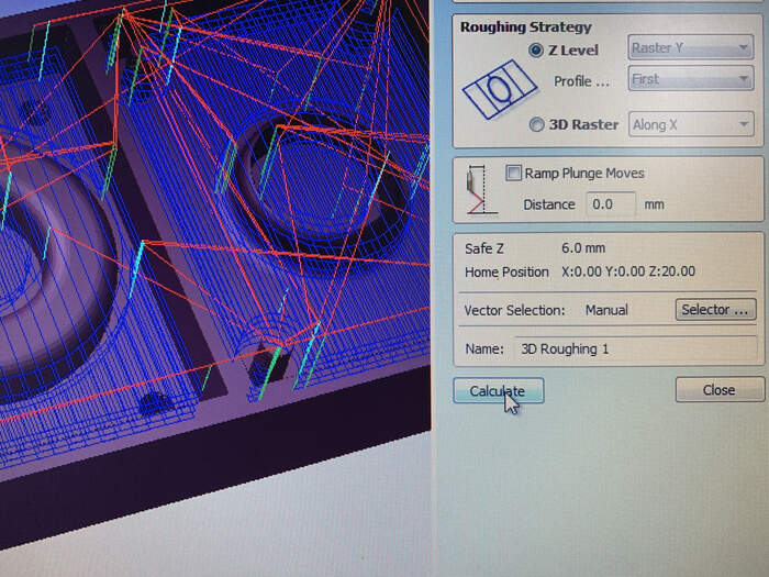
Set Machine limit boundary to material boundary, with a boundary offset of 0.0. The machine allowance is when it moves from one point to another the amount it goes up in the air) > 0.5mm. The Roughing strategy: X Level: you have (longer passes) than Y direction so we choose: Y raster (look at the pictures and see which one suits you best). Set profile to First. Keep the Ramp plunge moves (uncheck) with a distance of 0.0mm. Safe set: 6mm the amount it goes down. Give the toolpath a name and press Calculate:
-
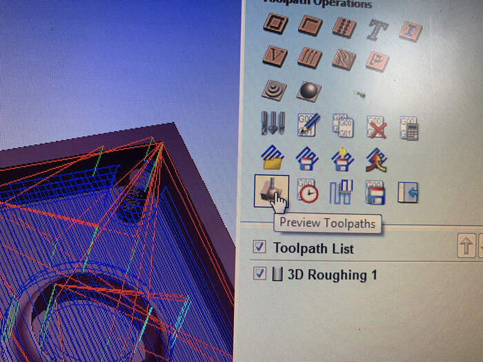
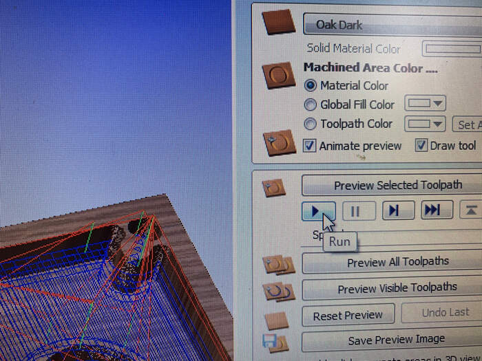
You can view the animations of toolpaths here to check if it will work as assumed with the Shopbot:
-
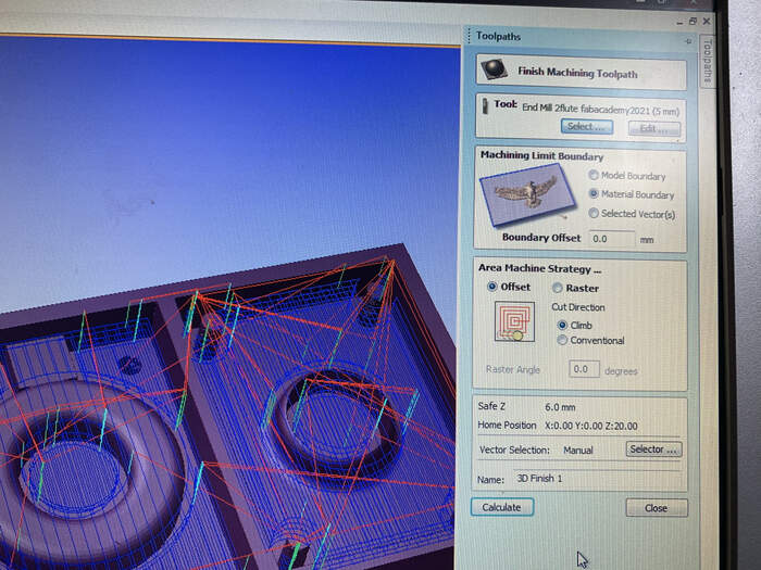
After this we will create the finishing toolpath: Create toolpath > Finishing toolpath
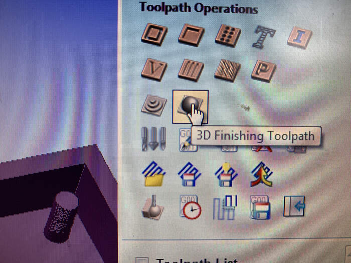
-
Select the same tool but in the stepover we change it to 0.5(this makes it more precise you can see it in the blue lines).In Machine limit boundary press material boundary. In offset or raster choose offset. Also check the climb option. Give it a name and press calculate.
-
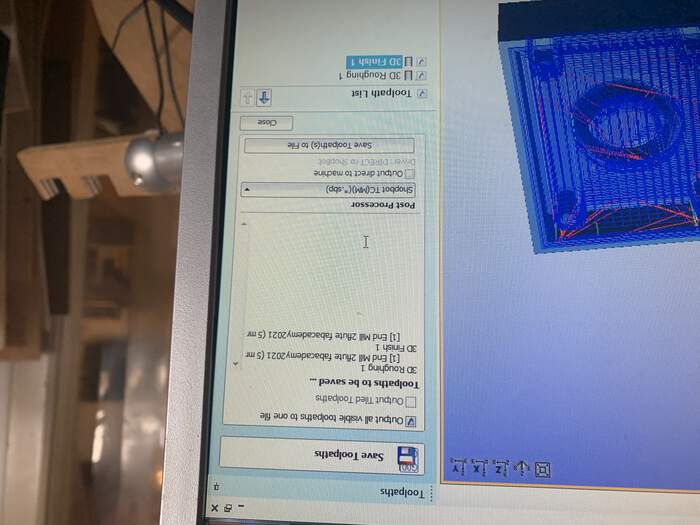
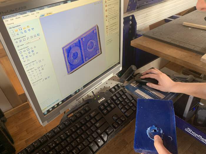
We now have two toolpaths, the blue lines are the paths the milling bit will do. We will now save them with this button:
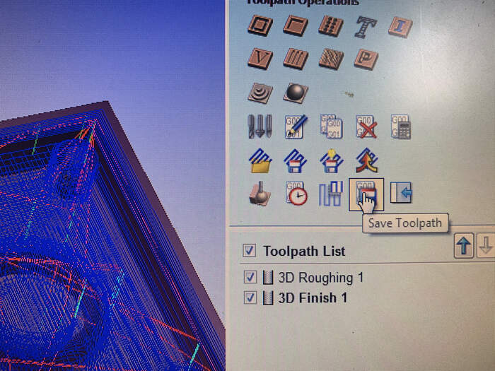
-
MAKE SURE YOU SAVE BOTH TOOLPATHS LIKE BELOW (OUTPUT BOX HAS TO BE CHECKED)
Setting up the machine to attach the wax block:
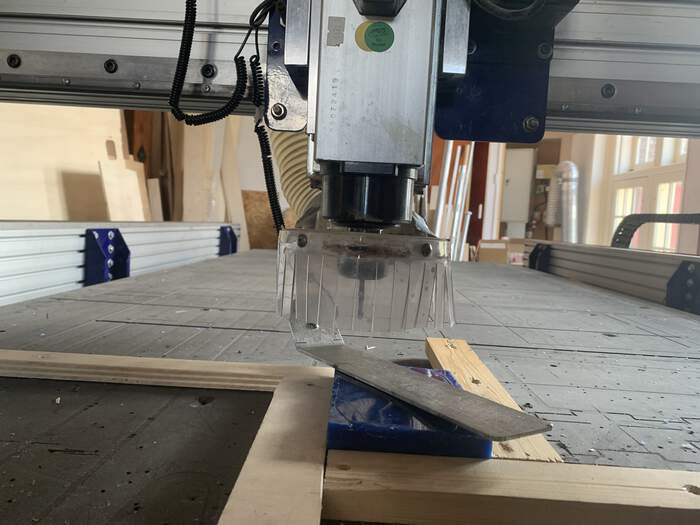
-
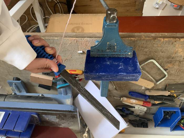
Sanded the wax block:
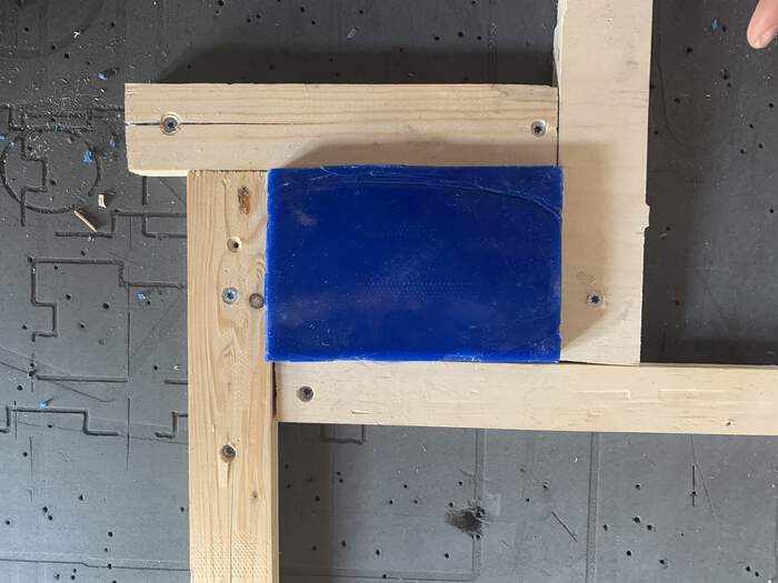
-
You attach the mould with pieces of wood which will be milled with small woodies (first you mill one side and then the other). You can also use tape underneath it. Make sure it does not move. And make sure you attach it on the right direction
-
Following Nadieh’s advice: Make sure to check that the distance from the tip of the milling bit to the collet is larger than the maximum depth that you’ll mill
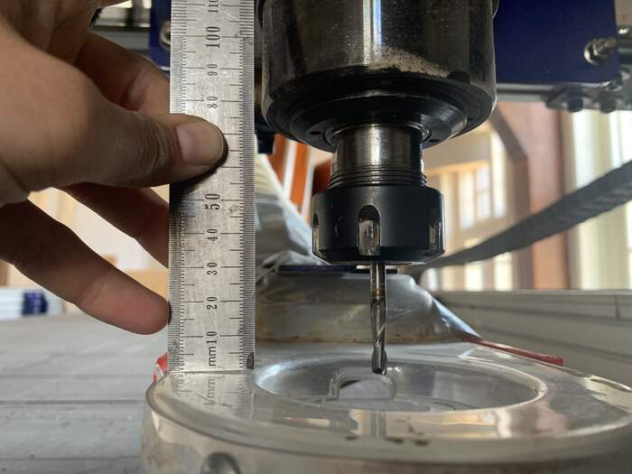
-
I leveled X and Y axis just as normal. in the right bottom hand corner. Took a picture to the coordinates before setting it up as always.
-
I then Z leveled in the smallest spot of wax block:
-
Also check the spindle speed, because although you set it up to 6000 in VCarve, the Shopbot will not know this, you need to manually set it up in the ShopBot to 6.0 with the little V7-4X box at the bottom-front

-
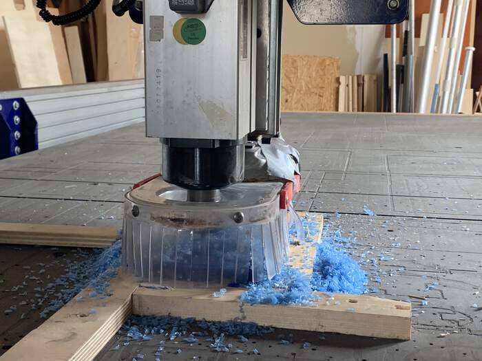
One important thing that changes from milling wood is that you do not turn on the extractor because it is milling away the wax and we want to reuse the wax again after.
-
I started milling but the wax block cut stuck to the spindle:
-
We went into VCarve and tried to see which was the error. I had not saved the toolpaths correctly (it was milling only the finishing toolpath). When saving make sure the output box is checked, as I said before.
-
Had to take the wax from the collet and then try again:
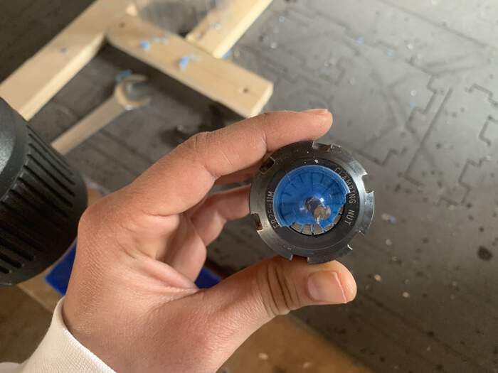
-
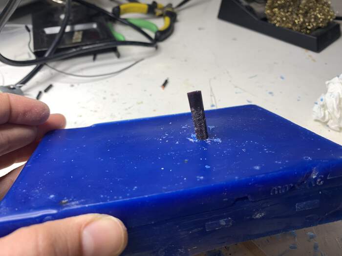
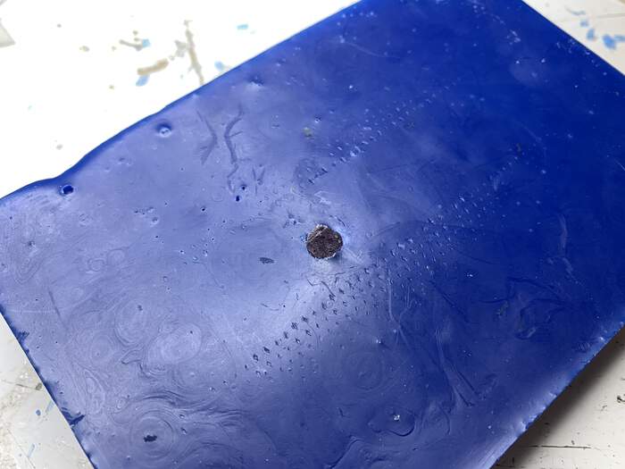
After this Henk helped me to attach the wood bits better, you have to really secure the piece, the milling went fine from on. It had a hole in one of the sides but we though that it would go through the middle holes and I could fix it later on with some wax:
-
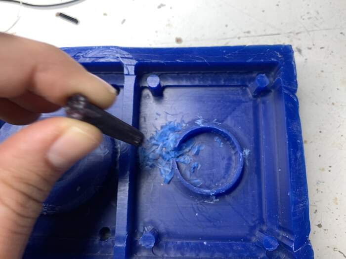
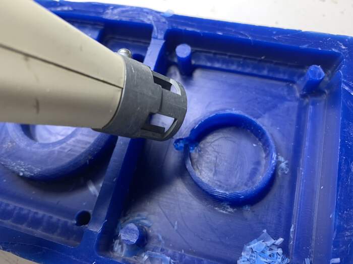
I realised the hole went through one of the walls:
-
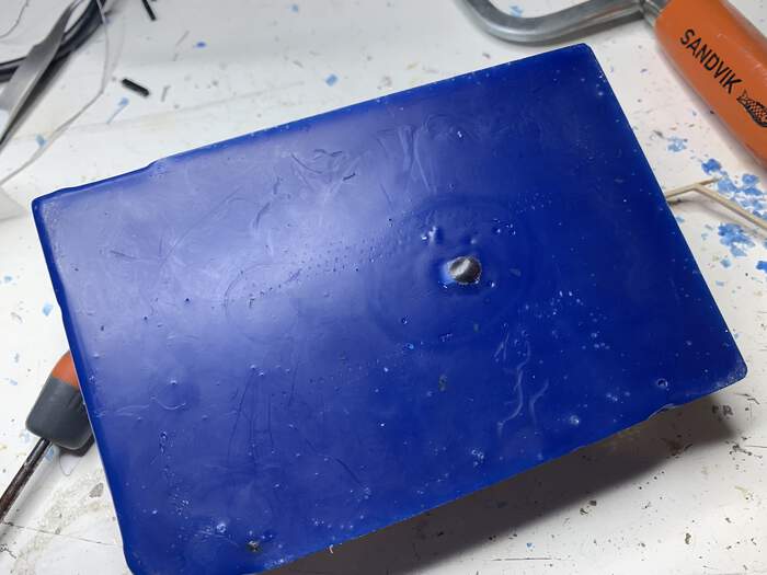
I tried fixing this melting wax in different ways, you have to be careful not to destroy the whole piece:
-
I fixed the hole but the wall tried to fix it with plasticina:
-
I also sanded a bit the rough parts.
Making mold:
-
I measured the amount of gr I needed for the mold as in the group assignment with water:
-
I will be using this silicone rubber for the mold
-
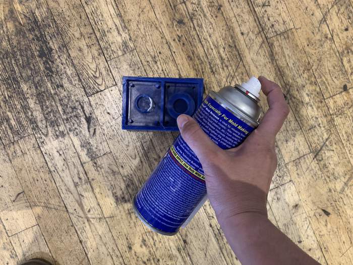
I gave the whole wax block a mist of the releasing agent and left it to dry 5 minutes:
-
I stirred the mix well and vacuum it so that it would release all the bubbles:
-
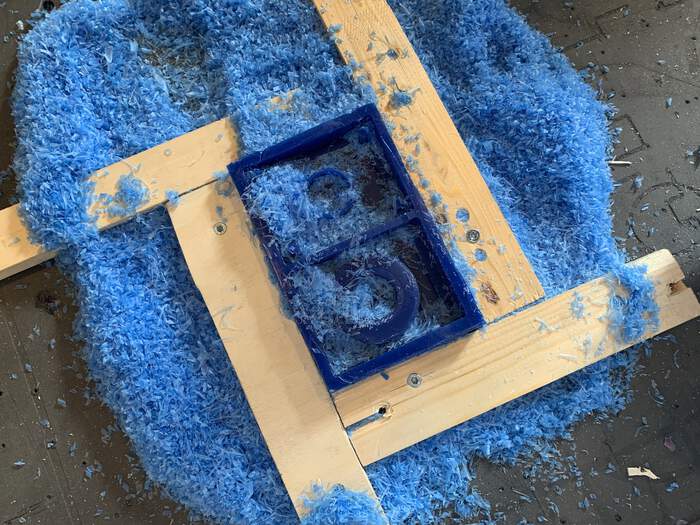
Poured the mix without bubbles in the wax block and left it for 6 hours:
-
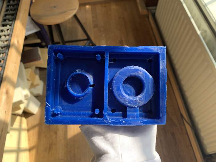
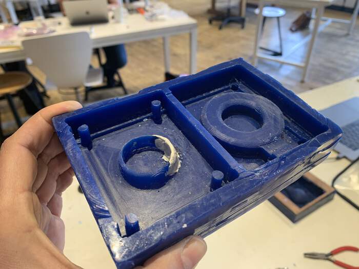
The next day I took out the mold, the plasticine experiment had kind of worked:
Making final piece:
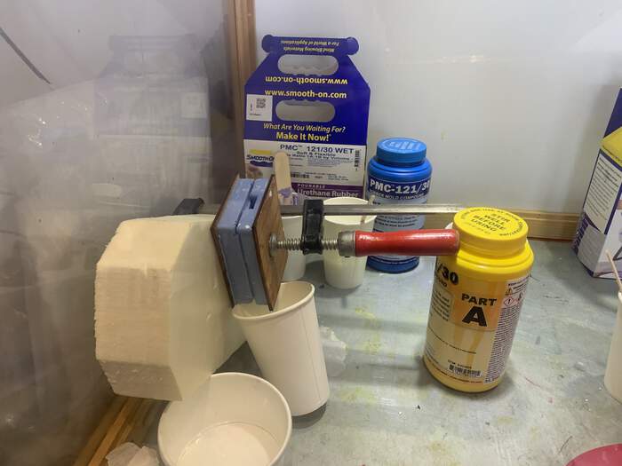
-
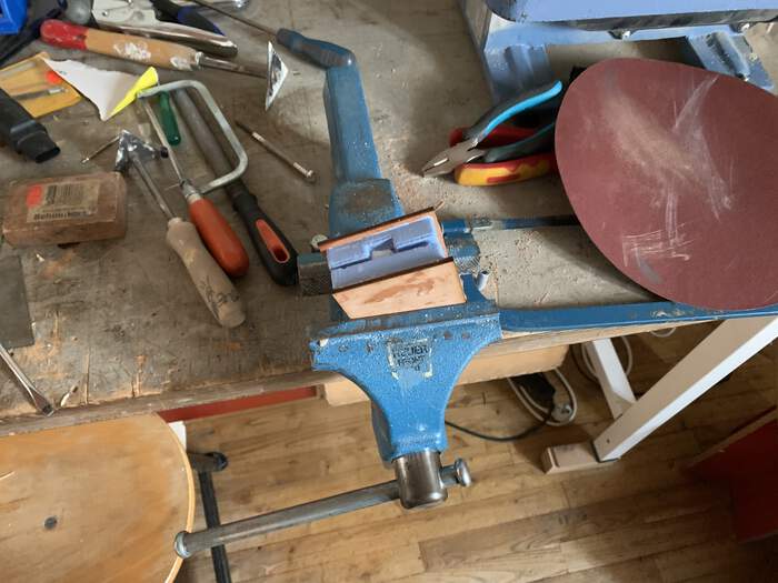
To secure the mold I laser-cut two pieces from a wood lying around in the lab and attached them to both sides of the mold.
-
I did my first piece with smooth cast
-
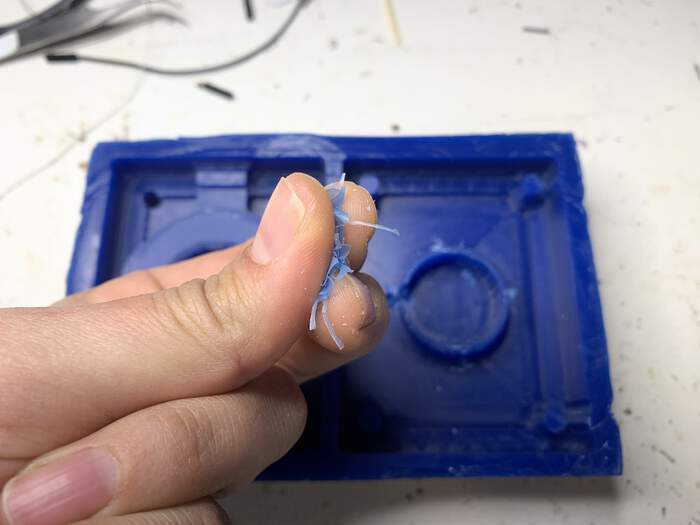
After 30 minutes, it came out quite dodgy, surprisingly the wall did not work, I don’t know why as in the mold the wall is there:

-
I am trying a new cuttings version with the AcrylCast material. This did not come out as expected.
-
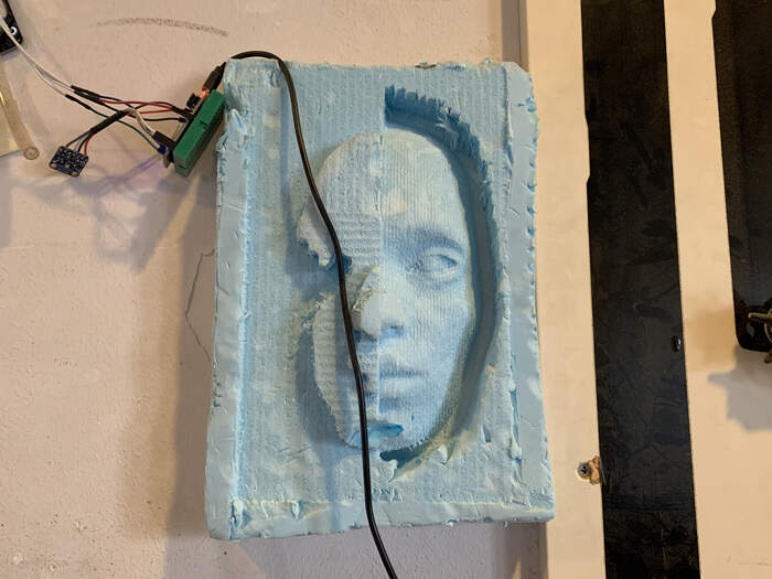
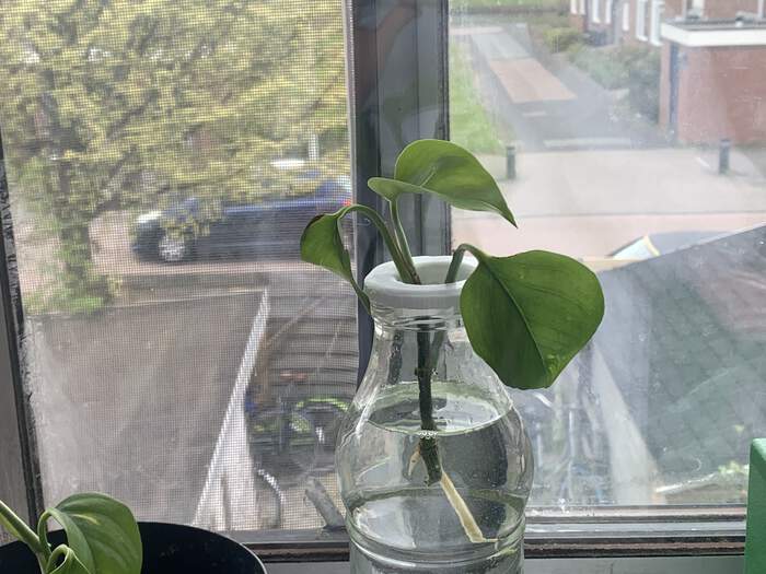
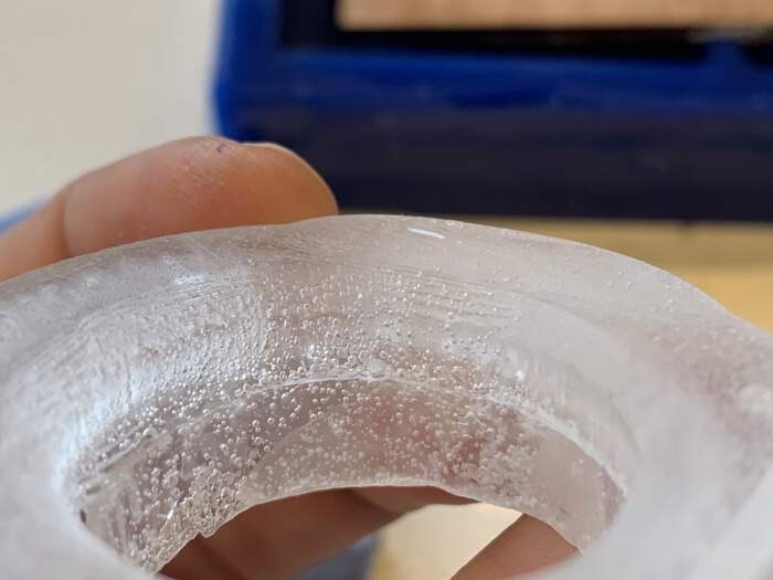
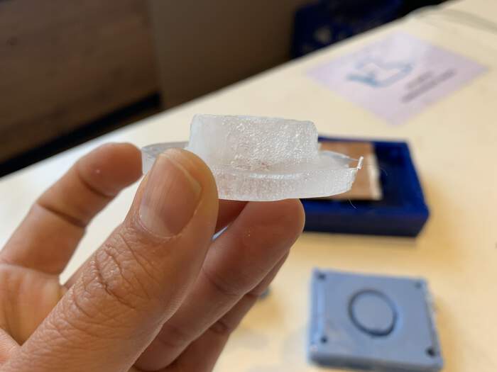
I will try tomorrow at the studio another more runny material. For the third try I used the Crystal Clear 202. The reason I used this was to see if by using a more liquid material the outcome would be better (as it would cover all the spots from the mold better). I made sure I clamped the structure correctly to avoid the material sliding through (I tried all sorts of positions, this was the final one haha but it worked).
-
The final outcome still had some damaged areas and the shape was not perfect. Also, I discovered the outcome of not using the vacuum pot. I also think the shape did not come out very straight because the clamping was not entirely straight either.
What went wrong? and how I solved it.
-
I should have done my shape completely Parametric to be able to modify it completely in the first place, the problem is that in the first shape I did everything parametric except for the holes which I forgot, this was my first problem. Making shapes parametric takes more time but in the end it saves times!!
-
Obviously not using a second wax block and trying to re-use the old one with the hole was a mistake, but this also made me look for creative solutions for it! Which kind of worked. But the final outcome was not perfect so in the future I will avoid re-using a wax block.
-
I also realised the fillet from the downwards shape did not get milled (the mill could not access it), I should have cut the shape a bit higher and leave the other rounded part for the other mold, turned upwards for the mill to be able to access this.
-
After trying different types of materials I realised the mold was not completely ok, this is why the final piece did not come out as good as I wanted it to be. Specially the registering points did not really fix the mold in place so that it did not move. Maybe in the next mold I do I will think about making it of a more solid material.
Files to this week’s assignments:
-
This is 3D .stl of the mold | stl
-
This is the VCarve file with the toolpaths for the 3D wax mold | vcarve