15. Molding and casting
This week is about molding and casting. Design a mold around the stock and tooling that I will be using, mill it (rough cut + (at least) three-axis finish cut), and use it to cast parts.
Assignments
- individual: design a mold around the stock and tooling that you’ll be using, mill it (rough cut + (at least) three-axis finish cut), and use it to cast parts
- group: review the safety data sheets for each of your molding and casting materials, then make and compare test casts with each of them
How can I use this in my final project?
Content
- Group Assignment
- Molding experiment - during week 13 & 14
- Creating a design for real molding and casting (assignment this week)
- Milling the model
- Creating the Cast
- Create a new cast with heatwires
- Create a new cast for a silicon model
- Files & Final conclusion for this week
Group Assignment
Review the safety data sheets for each of your molding and casting materials, then make and compare test casts with each of them.
Read all about our group assignment
Lessons learned
- The Silicon And PU materials are not so hazardous. Epoxy is. For all the following precautions are smart:
- gloves
- safety glasses
- long sleeves are recommended
- For Epoxy you need an extra ventilated area. A big room is not enough.
Molding experiment - during week 13 & 14
I don’t like to see the lines of the heatwires in the final painting. So I have to spread the heat. I described this in The Output week some experiments by spreading the heat with epoxy. One of the conclusions of this week was to make tests with copper powder in the epoxy.
This Epoxy resin (see specs sheet) I have at home (still no access to the Fab Lab). I used it to repair my surfboard. But it turns out to be for encapsulation of insects or other specimens. According to the specs one of the big advantages from other Epoxy rasins is: It is very fluid and the drying time is long so it won’t get hot. Both are not helping my application but if this is the only disadvantage It could work.
Making the copper powder
Base material. Old piece of pure copper: 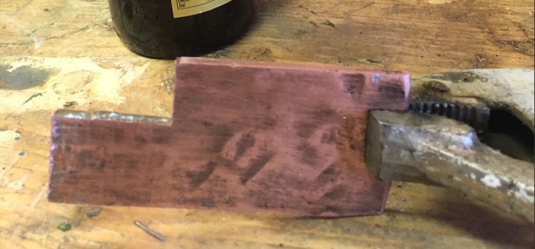
A picture of my father using a file to create copper powder, this method was used to create the large particles copper. 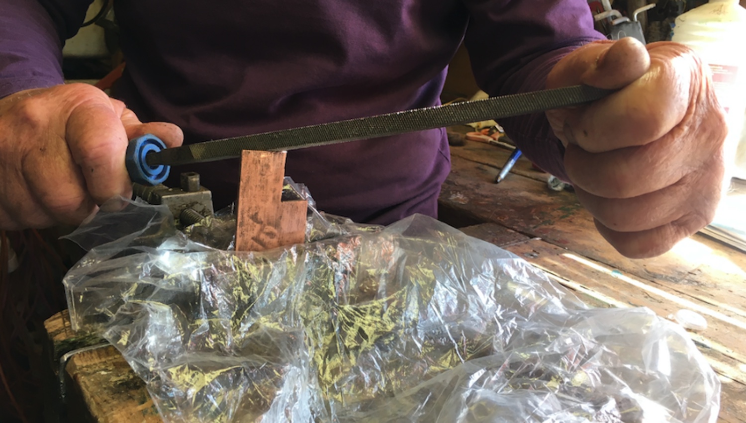
A picture how the fine and medium fine copper was made by Using a Belt Sander. 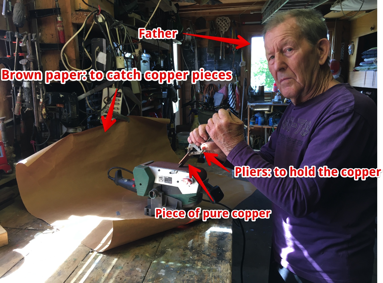
- Using a grain of 80 for the Small particles
- Using a grain of 60 for the Medium particles
Hero Shots: 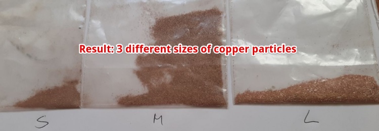
Make the heat spreaders with copper powder and Epoxy
While I made this week 13, I did not know I was ‘Molding and Casting’.
Create cups to hold the epoxy 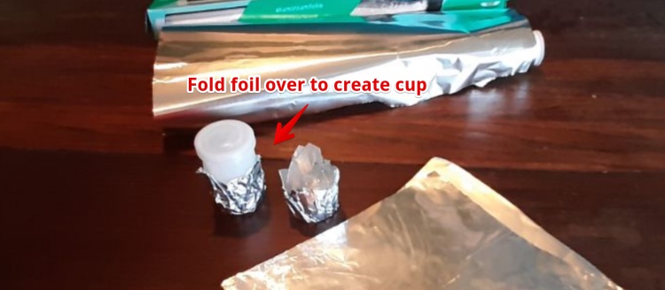
Fill cups with Epoxy/Copper-powder
Every cup is filled with 2 ml Epoxy, a teaspoon of filler and half a teaspoon of copper-powder 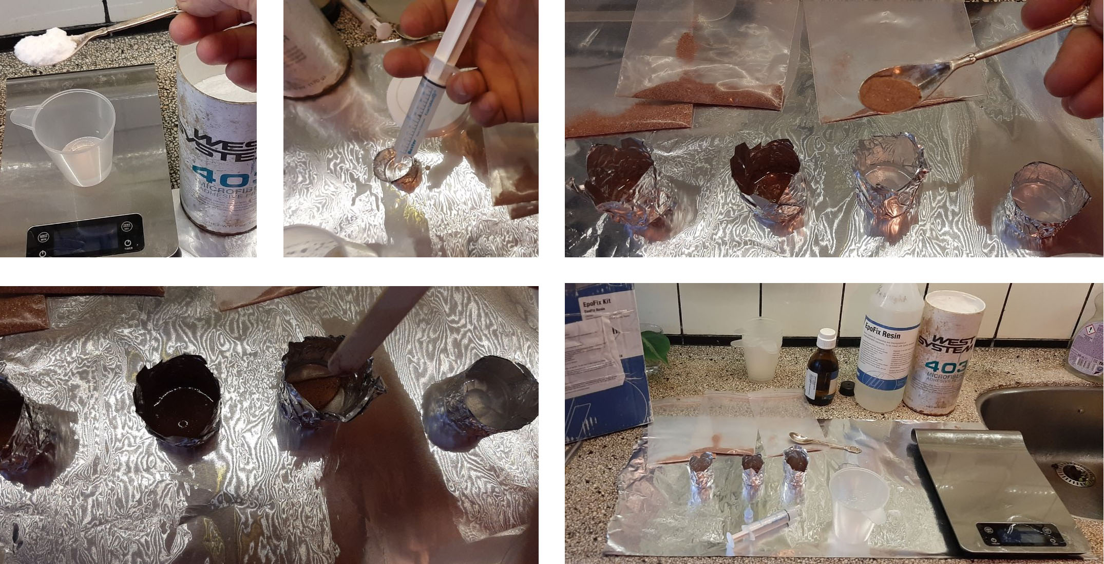
Problem getting the aluminum foil off:
The Epoxy is so sticky, it was impossible to peel the alu-foil off. Since aluminum is a very good thermal conductor (just below copper in the list) I had to do it by hand using a Dremel.
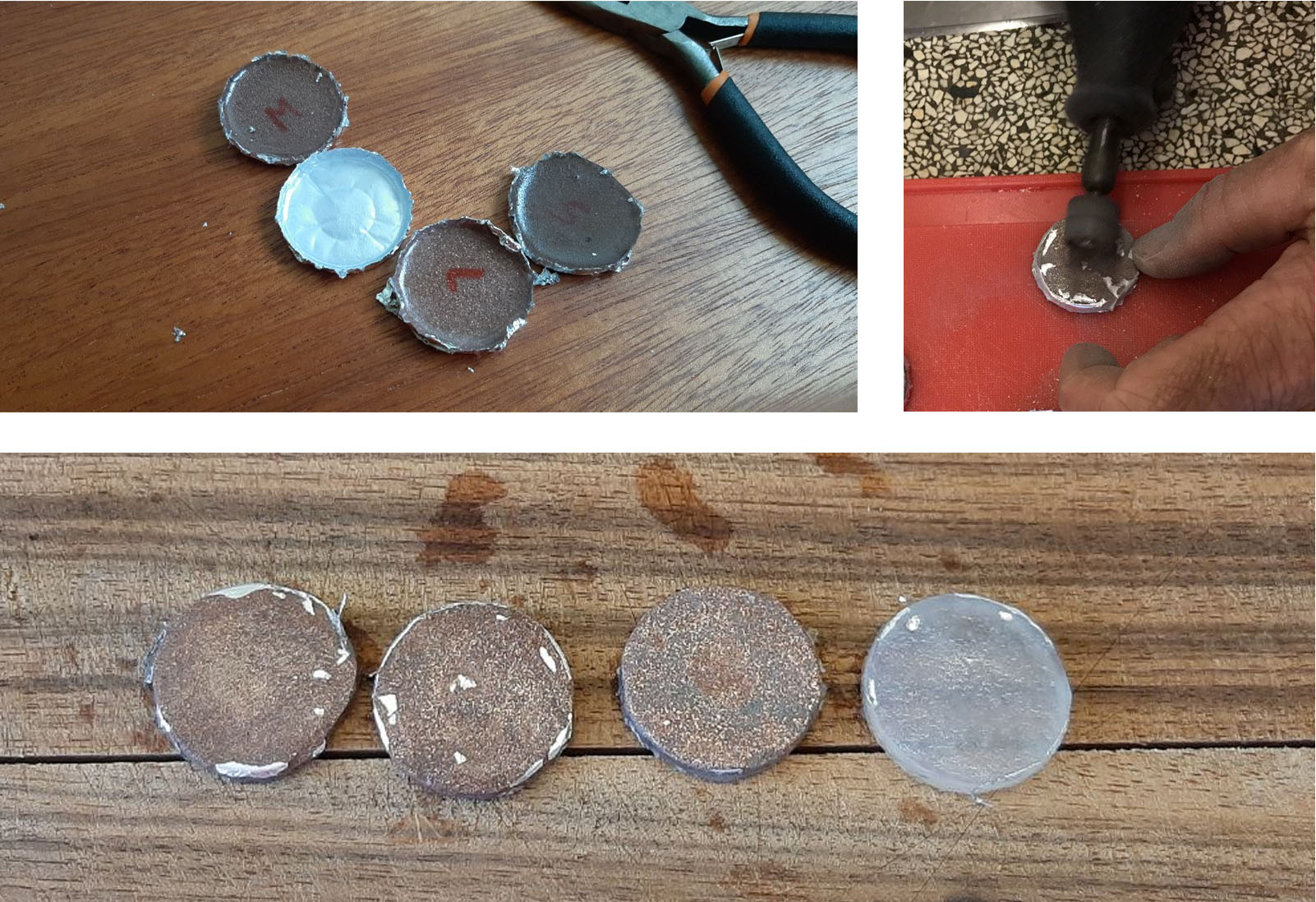
Will Epoxy with copper powder transfer the heat better?
To test this I could only rely on the things I had at home (no access to a FabLab due Covid-19). A body thermometer and my good old soldering iron.
The lowest temperature of my soldering Iron is 180C. According to this website: ‘Epoxies are capable of operating over the temperature range –250 °C to 175 °C, although in practice the maximum operating temperature is reduced to 120 °C and 50 °C’.
So heating it with 180°C will destroy the material a bit, I hope it will not melt.
Test method Thermal conductivity:
- put thermometer in (snug fit)
- heat soldering iron to 180
- Put soldering iron in and start timer
- wait till it reaches Hi (max 42°C on this body thermometer)
- Record time
Test method electrical conductivity 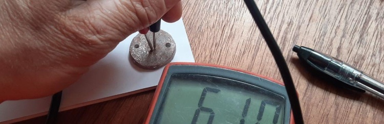
- Used the multimeter on the highest range (2MΩ)
- First measure in the holes, than with the probes really close.
- I had to firmly press to get a reading (only by the Large particles)
| Material | Thermal resistance | electrical resistance |
|---|---|---|
| No copper | 30 minutes < 36°C | > 2MΩ |
| Smal particles | 30 minutes < 36°C | > 2MΩ |
| Medium Particles | 30 minutes < 36°C | > 2MΩ |
| Large particles | 30 minutes < 36°C | 600 KΩ |
The method above failed!
Even after 30 minutes the thermometer stayed LOW (<36°C) with all materials. I resided to drill the hole closer to the thermometer and raise the temperature to 250°C. And I wanted to keep the heat transfer trough the air to the minimum put the Iron on the one side and the thermometer on the other side.
New test Setup:
Temperature is 250°C and the soldering tip is really close to the thermometer 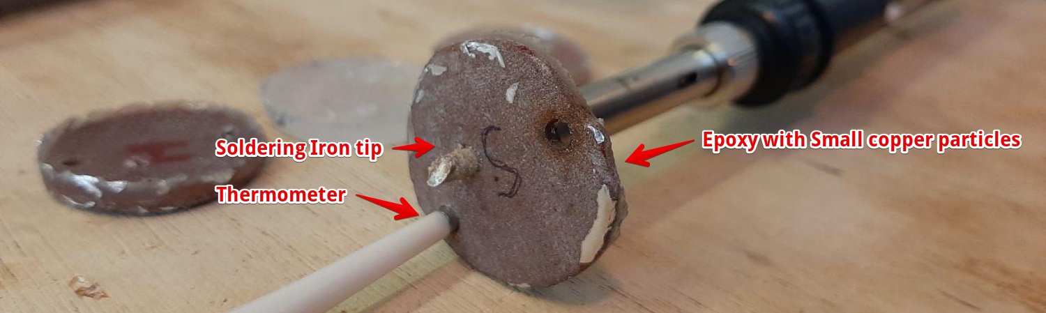
Test Results:
| Material | Time to reach the max of thermometer (42,7°C) |
|---|---|
| Epoxy: No copper | 7:09 minutes |
| Epoxy: Small particles | 2:26 minutes |
| Epoxy: Medium Particles | 1:45 minutes |
| Epoxy: Large particles | 2:58 minutes |
| Silicon: Small particles | 2:10 minutes |
I later made an silicon test piece: Silicon 14 with small copper powder and included this in the table above.
Final conclusion using copper particles on top of the heatwires
- The electrical resistance is high enough (consider the heatwire is 1 ohm)
- Copper particles increased the thermal resistance a lot (can’t say big or small is really different)
- I could not exactly measure the copper I used for the different Epoxy pads. So this will contribute to the difference between particle sizes.
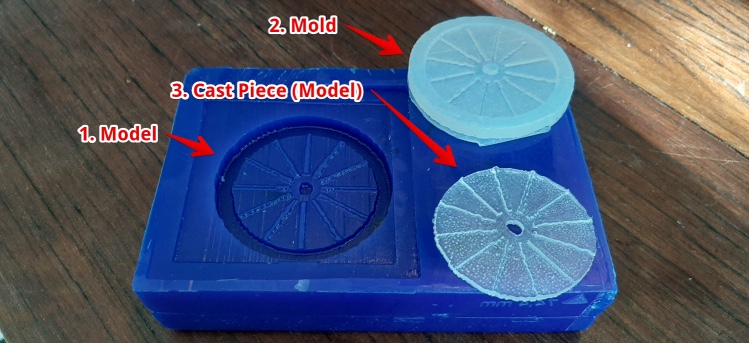
Creating a design for real molding and casting (assignment this week)
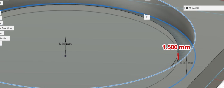
In our lecture from the Fabacademy the basics of Model & Casting is explained. To keep both separate, I made the drawing below. It helped me to stay sane. My experiments with the heat conducting materials helped me a lot.
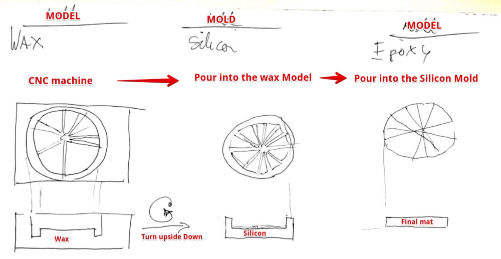
The model
I decided to go for an heatpath of heat conductive material. 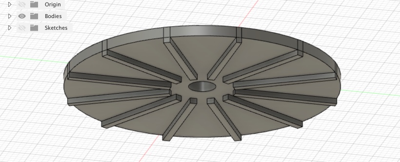
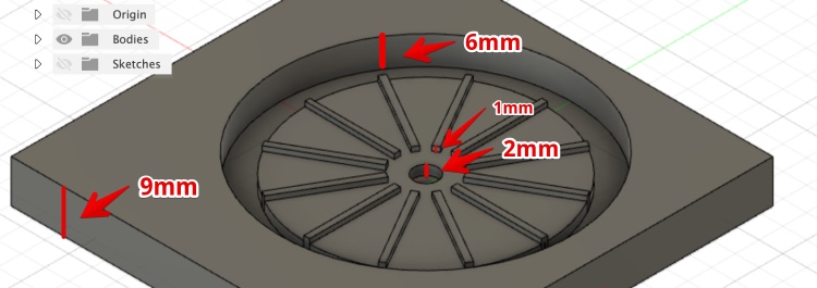
The mold and its dimensions
Lessons learned
- I went into ‘upside-down-inside-out-mirrored-confusion’ modus a few times. The hand-drawing helped me to stay sane.
Milling the model
In general, it some steps are the same as the ‘make something Big assignment in Week 7
The big differences are:
- Think in 3D
- Fix the material using Wood and double side tape
- Import an STL
- Use the 3D view in Vcarve
- Make two toolpaths (rough & finish)
- Use low spindle speed (6000)
- Don’t use the vacuum
- Use higher travel speed (speed/feed around 100)
Steps
Fix the wax block on the table: DON’T DO IT ON THE SIDE AS IN THIS PICTURE (the wax will be spilled next to table) 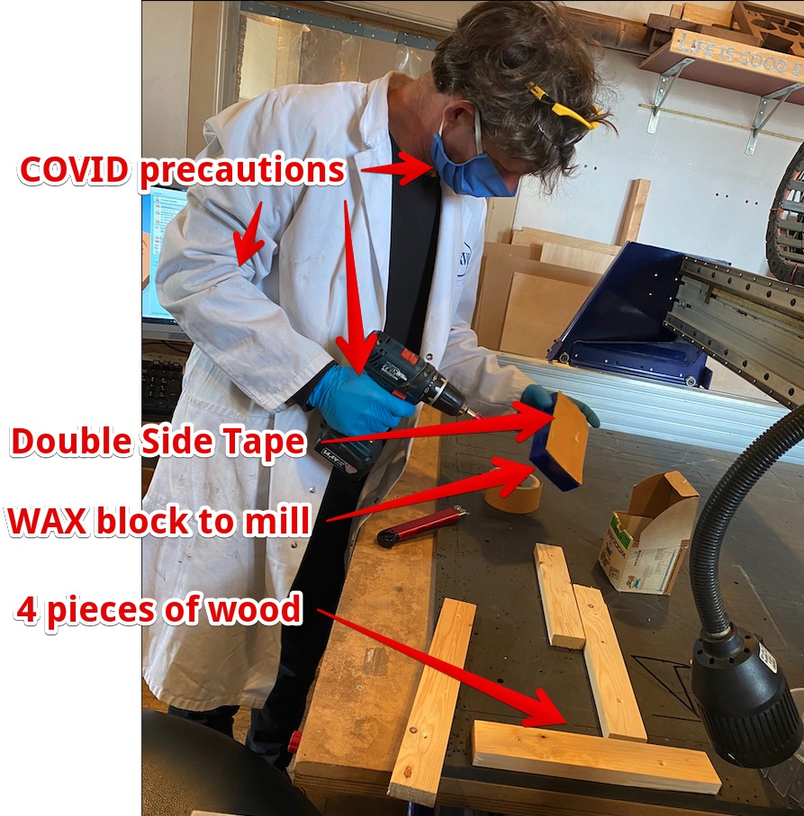
Make the top of the WAX block flat 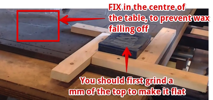
Make sure the mill is long enough to go into the deepest part the material.
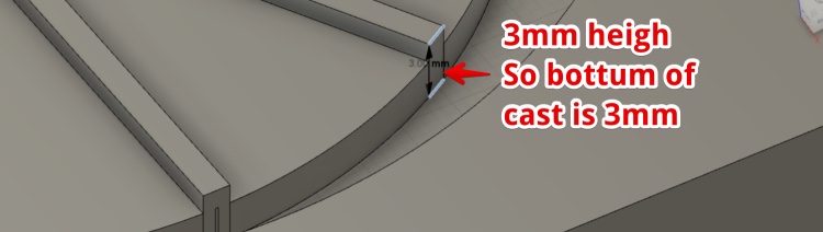
I checked all dimensions. My Model is only 9 mm high,the deepest part is 6 mm from the top. So the head will not touch the wax. I let the Mill stick out 15 mm to make sure It could never be a problem.
VCarve
- Get your STL (from Fusion Ready)
- Open VCarve
- Create new file
- Set dimension (see picture ) of block
- press OK
- File Import, Component/3D model
- Import > go to tab 3D view
- Prepare size and dimensions: Make the material size the same as the object size
- Change Orientation
- Move the object (in the Z direction )
- Center Model (Red lines are material)
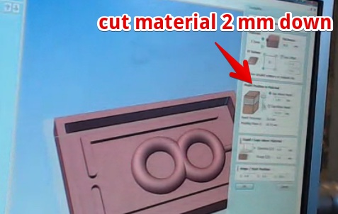
- Toolpaths
- Set …
- Model Position in the material
- 3D Roughing Toolpath
- Machine limit boundary
- Model boundary
- Boundary offset
- Machine allowance: keep it
- Roughing strategy: keep
- Ramp plunge moves (protect the movement): put on 5 mm
- Machine limit boundary
- Select the Mill
- Set speed to 6000
- Feed rate (both): 50 mm/sec
9 Press Calculate
Click Toolpahts
- Reset preview
- Preview all toolpaths
Change the boundary 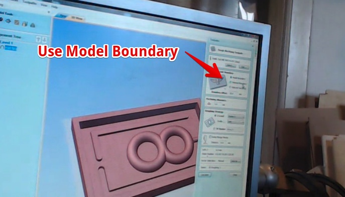
Plunge ramp: don’t go straight in the material, For now it does not matter. Just use 5mm 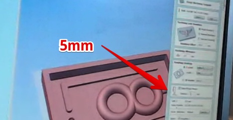
Press calculate 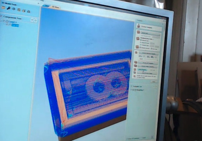
Now do show the path
Now do the finish
- can be with the same mill
- use a higher stepover
At the end export two toolpaths File > Save As 
ShopBot & Start CNC
- Make sure the table is free
- Turn the machine on (red switch on side)
Open ShopBot software
- Zero the (X-Y) of material
- move the machine up (keypress ‘k’ move Z-up)
- press ‘K’ and move the head to Lower left of material
- In Menu Menu: [Z]ero > Zero [2] axis (X & Y)
- Zero the Z of material:
- Move to middle of material
- Put the metal plate under
- Press Z-BUTTON
Record the x,y and z (make picture)
- Start Spindle
- Start spindle (turn key)
- Set spindle speed on the CNC table to 6.0 (= 6000)
- Starting the Milling
- File > Open > .stl (rough toolpath first)
- Set speed to 100/100
- Keep hand on space bar
- Press START
- Press the OKE warning two times
Problem with the Z adjustment
- Since my wax block is really hollow from the top, it has no flat surface. I desired to scrape some of. I placed the auto Z ax plate on the left of the block. This will stay untouched, so I have a good Z- reference when changing the Mill to Ball end.
While milling I noticed It was not taking off the flat part. So the mill did not go deep enough.
Hero Shot: 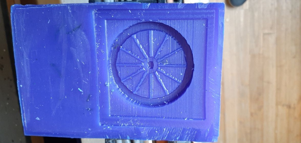
Lessons learned
- The material is not flat. Look what the difference is between the highest point and the lowest. use this as an offset.
- I had the material on the side of the beth. The wax fell of the table. Put the material in the middle of the table (so save wax and cleaning time)
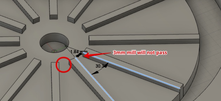
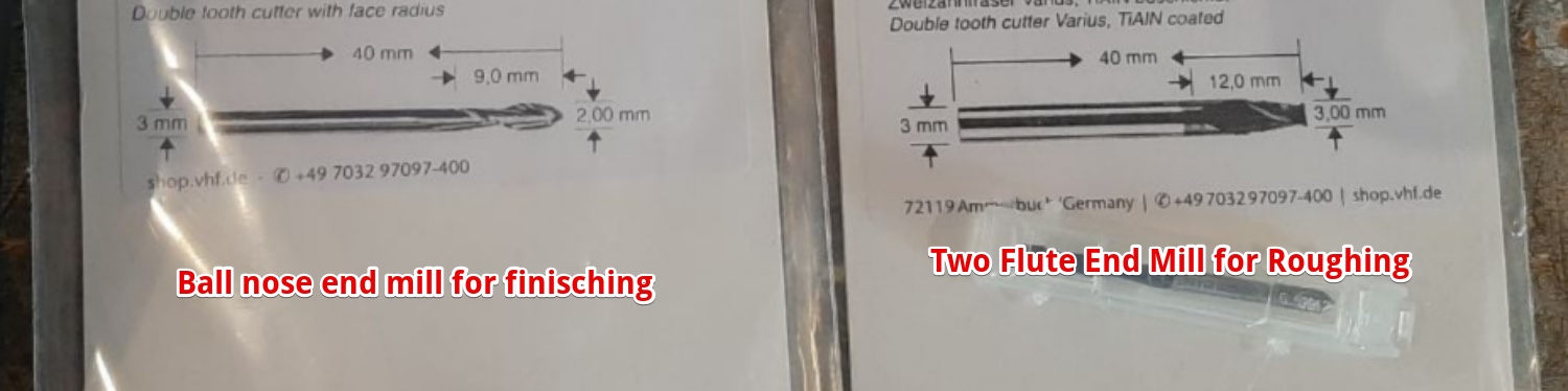
- The finish is really rough. I used the ball nose mill. Don’t use a ball nose Mill to finish for flat surfaces
Creating the Cast
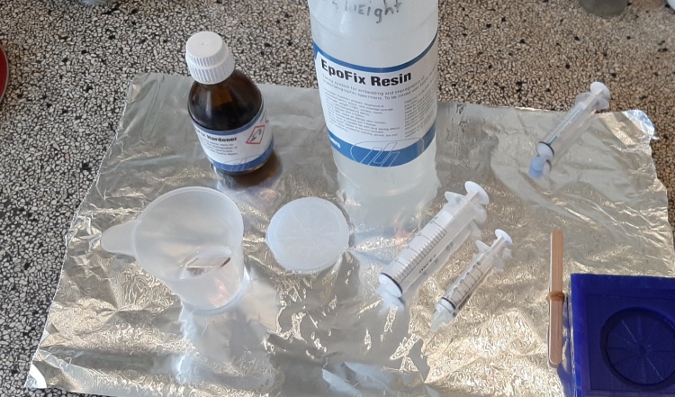
The material I used is: “Silicone Addition Transparent 15 Fast (Soft)” Datasheet “The Silicone Addition Transparent 15 Fast is a 2-component (poly-addition) pourable silicone which, very rapidly, cures at room temperature to a quite soft but strong rubber silicone. This is a Skin safe and food grade silicone!”
Safety:
- “If you use silicones frequently we advice the use of gloves and to work in a properly ventilated area. For safety information see the safety data sheet.””
- Safety sheet Silicon Addition 15 Fast (soft)
Use:
- Mix A and B (1/10)
- Working time 2 minutes
- curing time 15 minutes
First pray Release material on the Wax model 
I used this Silicon 15 (1/10) and mixed it for 10 seconds 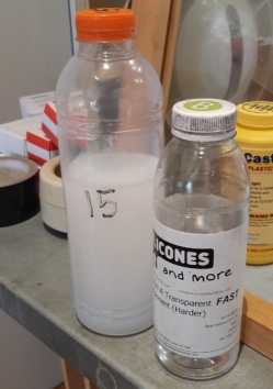
I used the vacuum chamber (real quick for 30 seconds) 
Check for bubble’s 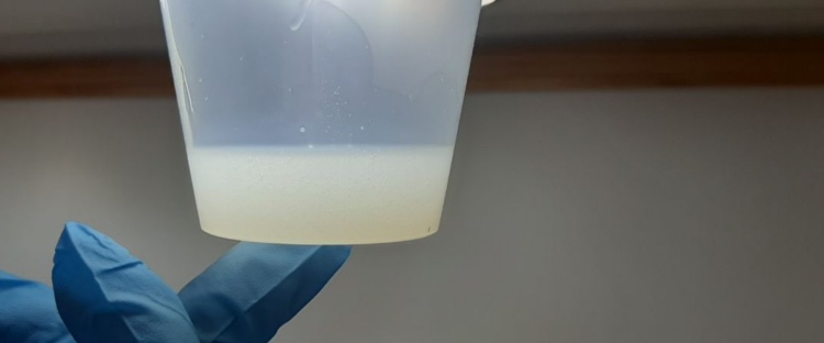
Pour into model. All within 2 minutes…
Hero shot
Create the model in hard material
Since I was outside the lab I had only the Epoxifix to try. The EpoFix is not as harmless as Silicon. The Safety sheet states:
Precautions:
- Use Gloves
- Use Safety glasses
- Use a very ventilated area
- Long sleeves
Use:
- Mix 3/15 volume
- Mix Weight
- Curing time: 12 hours
- Pot live: 30 minutes
While filling I noticed the epoxy was not flat due the cohesion of the Epoxy Resin. So I used the wooden stirring stick to scrape some off. 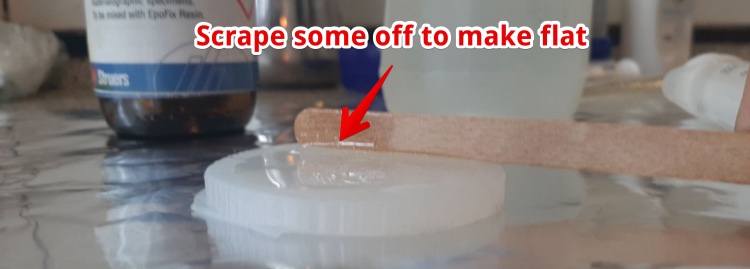
Hero Shot:
Create a new cast with heatwires
Since the goals is a cast with heatwires and copper powder I had to cut in the mold where the heat wires should be. 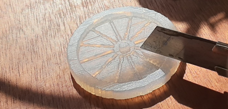
When I wrapped the heatwires around so they would fit in the mold. The mold was not flat anymore: 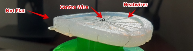
From the top it looks fine. 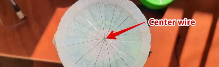
All the materials Used 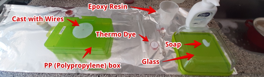
I decided to put something on top of the Mold to make it flat again 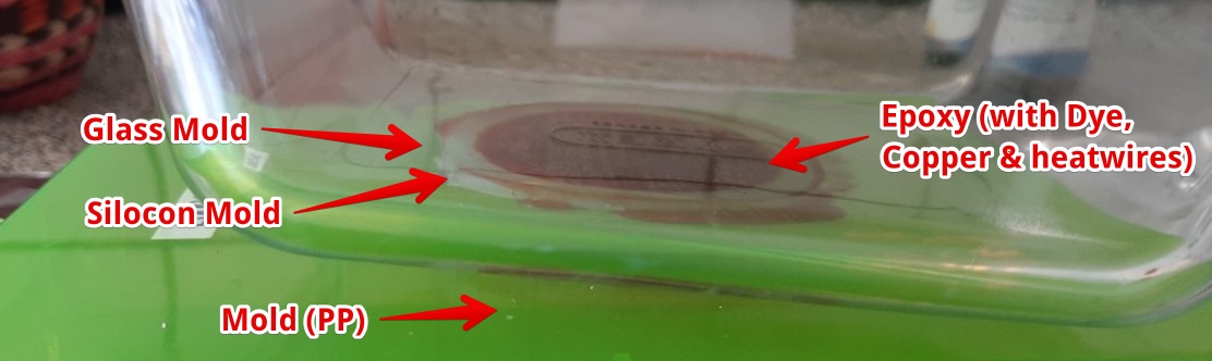
The next day the epoxy came of from the PP box without a problem. But was really stuck on the Glass: 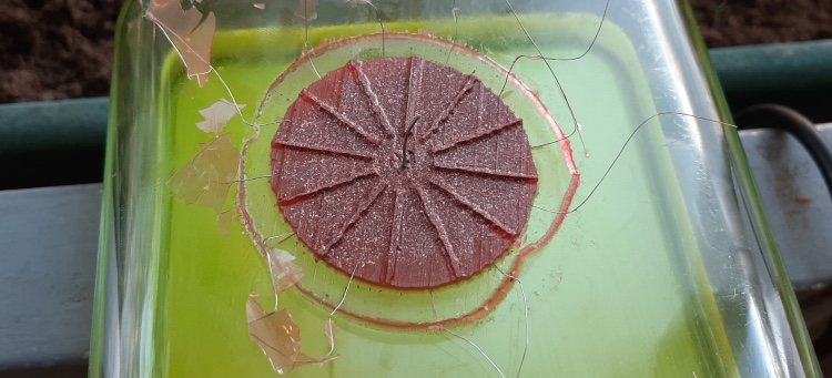
I had to use a knife to get it off, the epoxy broke on several places… 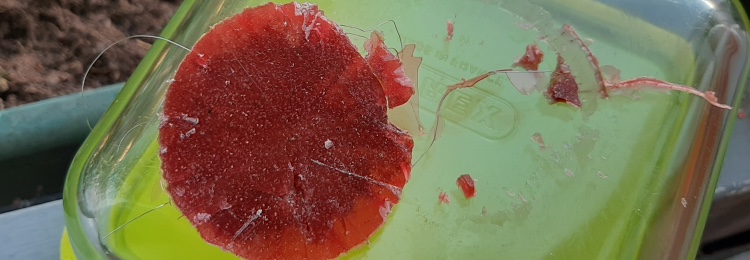
I lost 2 of 12 wires (broke off in epoxy) 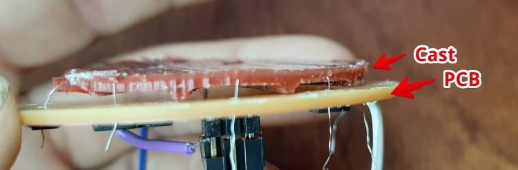
But I was able to connect the wires from the Cast on the PCB 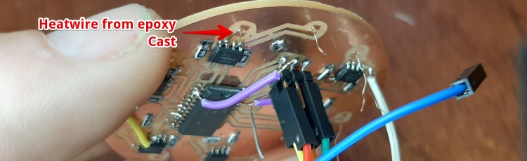
But only one of the remaining wires really heated up (green color). One other wire was a bit connected. 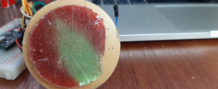
The problem is in the central connection. This wire was only touching the wires when I applied the epoxy.
Lessons learned:
- Copper will go to the bottom
- Epoxy really sticks to Glass, don’t use glass as molding material for epoxy, it sticks
Create a new cast for a silicon model
I would like to create heat-transfer that is kind of forgiving when it comes to shape. It has to be on the back of the painting and touch as good as possible. So I removed the ribs.
For this flat surface connecting to the back of the painting a hard material is less suitable. So I looked into soft material. Silicon is the most flexible material we have at the Waag. I will try to increase the heating conductivity by adding copper.
But can I cast with silicon and than make a model from silicone?
According to the FAQ at Smooth-on (the major brand we use at the Waag) it is possible: “Silicone-to-silicone applications such as making two-part molds or casting silicone into silicone are possible, but require a release agent.” But I need a release agent, they advice:
- Mann Ease Release™ 200
- Petroleum jelly (Vaseline) - with a bit of material spirit (to make more fluid)
Since we have Mann Ease Release™ 400
The difference between Ease Release™ 400 and Ease Release™ 200 is found on the application page.
| Use | Ease Release™ 200 | Ease Release™ 400 |
|---|---|---|
| To release | Polyurethane, epoxy, polyester, PU-foam, Silicone. | Get polyurethane elastomer, Thiokol rubbers, EPDM, Synthetic elastomer from aluminum chrome, polyester, rubber, steel molds |
I looked up what the Synthetic elastomer are. https://en.wikipedia.org/wiki/Elastomer states Silicon Rubber is an Elastomer too, so I take my changes (I don’t have any other release agent now). If not working, Ill try Vaseline with material spirit.
I did a test with Silicone 15 in Silicone 15. This worked.
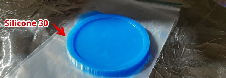
Then we where out of silicone 15 and bought Silicon 30.
I used the Mold Star Silicon 30 to make the new casting.
Lessons learned
- I can mold and cast with silicone in silicone.
Files & Final conclusion for this week
Files
Conclusions
- Molding and casting is fun, but the applications are limited for my final project
- I can decrease the thermal resistance of silicon a lot by infusing with copper powder
Biggest Mistakes and lessons this week
- I’m trying to create a flexible heat conductive material by adding copper to silicon. But the copper makes it stiff.
- Using a boll nose end mill to make flat surface is not smart. I will use a flat End Mill for the finishing next time.
Wat I really liked
- I got ‘kind of’ friends with our big CNC machine
My concerns
- I still don’t have a final plan making the heatpaths