7 - Computer-controlled machining
The design process for the CNC machine milling machine. Test runout, alignment, speeds, feeds, and toolpaths for your machine. Make (design+mill+assemble) something big
How can I use this in my final project?
- Before I thought i could not use this. But now i finisched it I found out the beaty of the wood structures are so mutch better than the painting frames i have at home. So For my final project I would like to make a photoframe. (Or 3 to match it in my kitchen)
The steps for this assignment
- 1. Group: find the specific of our CNC machine
- 2. Safety instructions - How to operate our CNC machine
- 3. An overview of the functions
- 4. Replacing a Mill
- 5. Fusion 360 - Designing for the CNC milling machine
- 6. Illustrator
- 7. VCarve Pro - Prepare a file for the Shopbot software
- 8. ShopBot
- 9. The Final result - the panels
- 10. The Final result - putting it together
- Files & conclusion for this week
1. Group: find the specific of our CNC machine
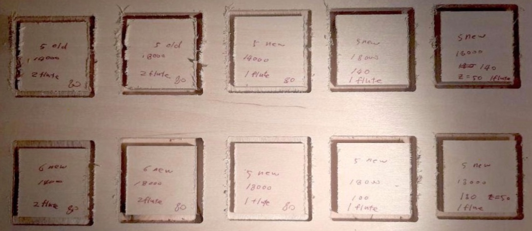
Test runout, alignment, speeds, feeds, and toolpaths for our machine read all about this group assignment
2. Safety instructions - How to operate our CNC machine
| 1 | Don’t get to close to the machine when the machine is on. | 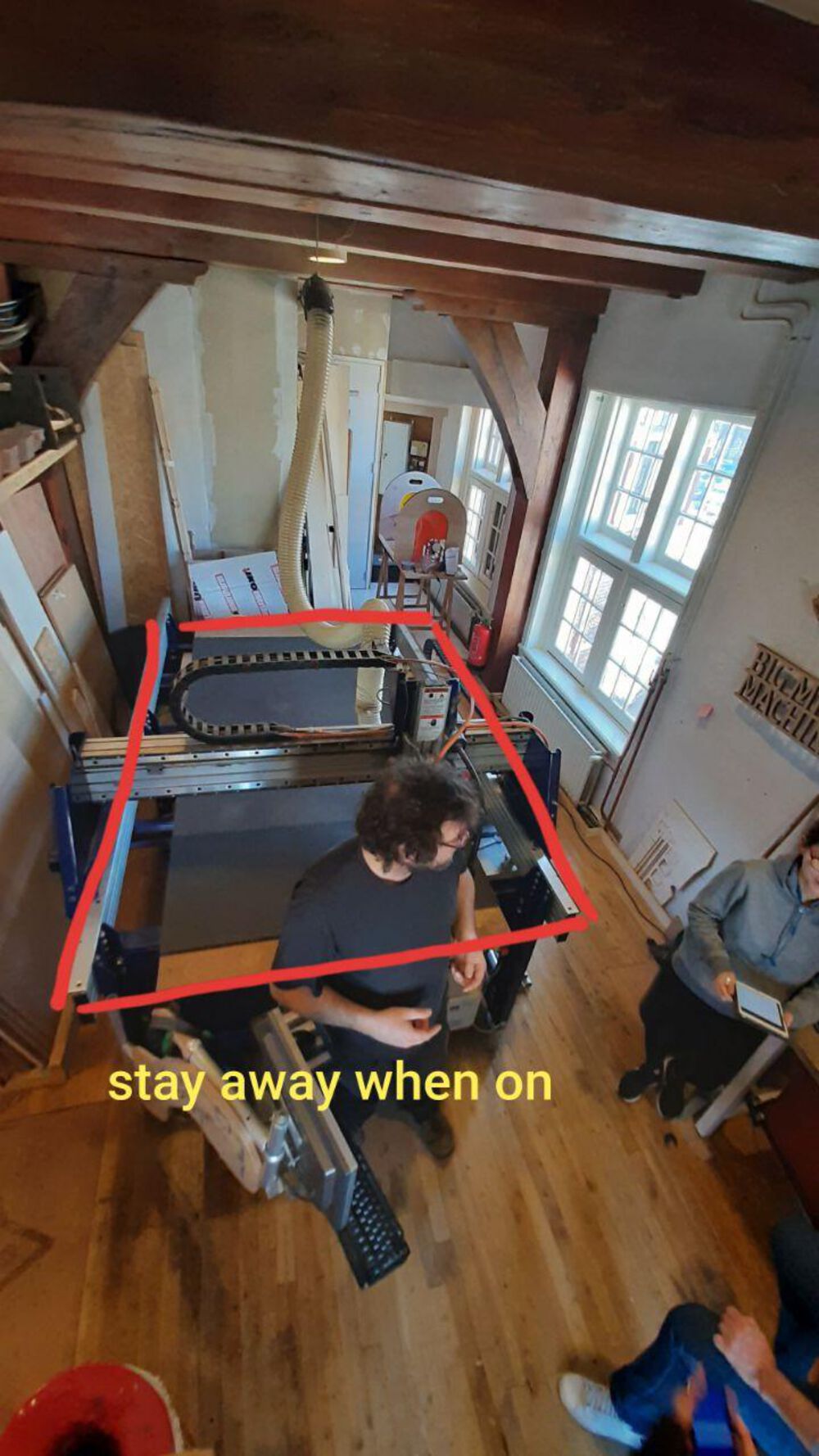 |
| 2 | Keep the machines and surrounding clear | |
| 3 | Don’t operate the machine when: | You are not calm, So Start in Time, Don’t rush. You have loose long hair, or wear anything loose, possible getting cough by the mill |
| 4 | Beware of the emergency exit | |
| 6 | Wear glasses | |
| 7 | Beware of the Fire extinguisher |  |
| 8 | Be aware for fire in the bin (Dust collector)! If you hit a Screw with the Milling Bit. Or you smell a burn: ALWAYS check the BIN/Dust-collector. | 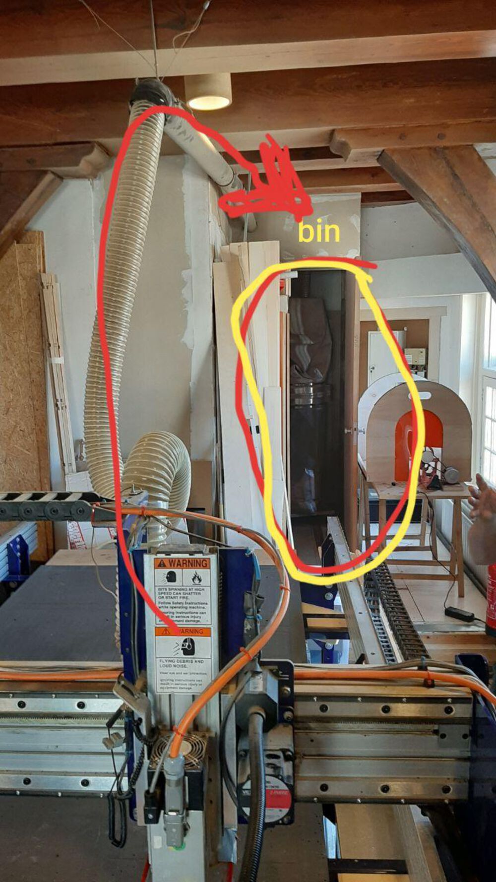 |
| 9 | In case of smoke or any doubt put the bin outside the building! | |
| 10 | Loose/wobbly milling bit: check if the bit rotates evenly before you start hitting the material | |
| 11 | Don’t hit a screw: Make the material dimensions in VCarve Pro smaller than the actual wood, so you will never hit a skrew on the side |
3. An overview of the functions
| 1 | Axes of movement of the machine | 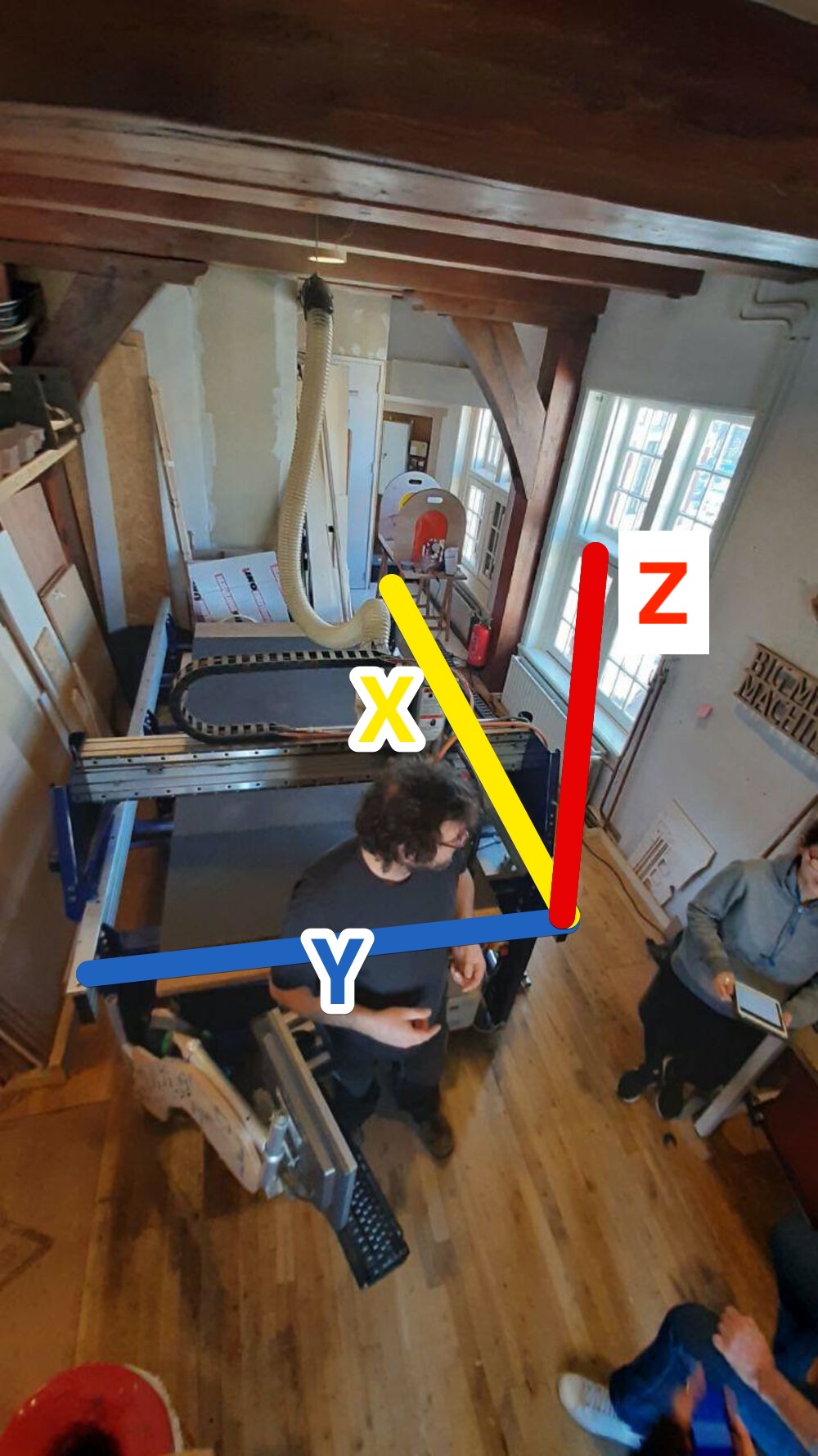 |
| 2 | Milling system | 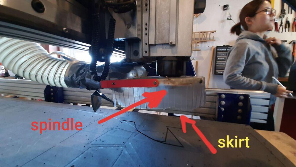 |
| 3 | Dust collecting, at the mill | |
| 4 | Dust collecting, from machine to Bin | 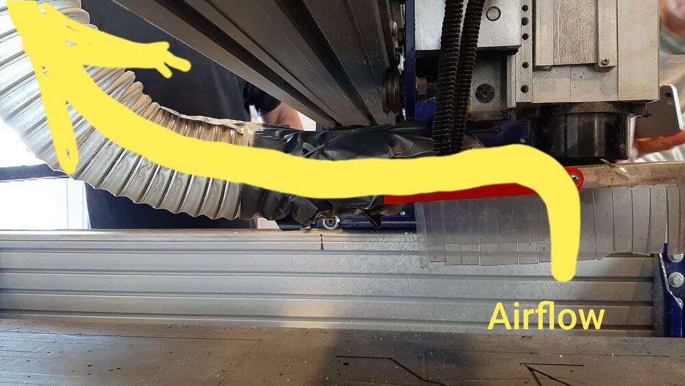 |
| 5 | The keyboard should be sideways | 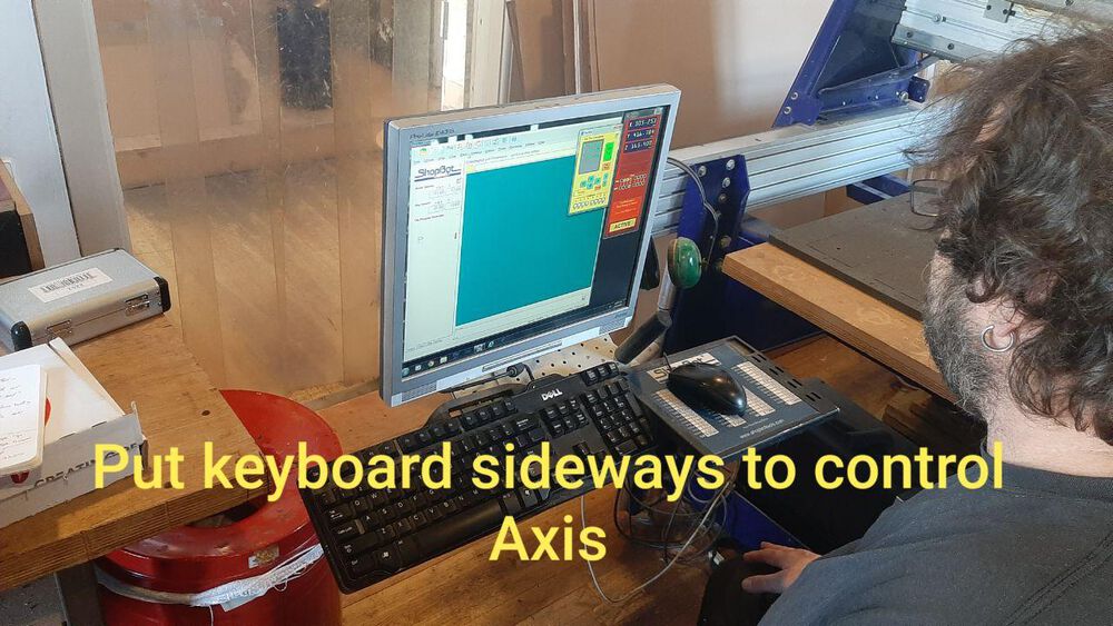 |
| 6 | To have proper mapping with the axes | 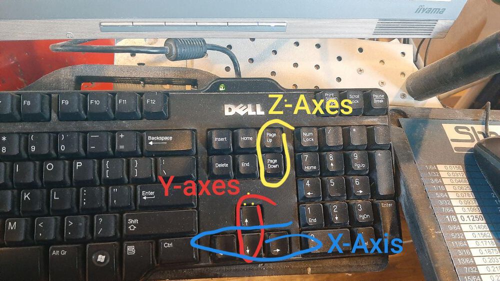 |
4. Replacing a Mill
| 1 | Loosen the Wing nut to lower the skirt | 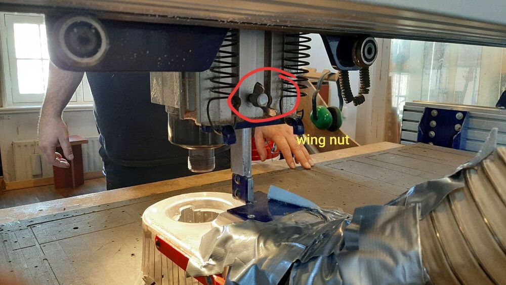 |
| 2 | Only use Metric Mills | 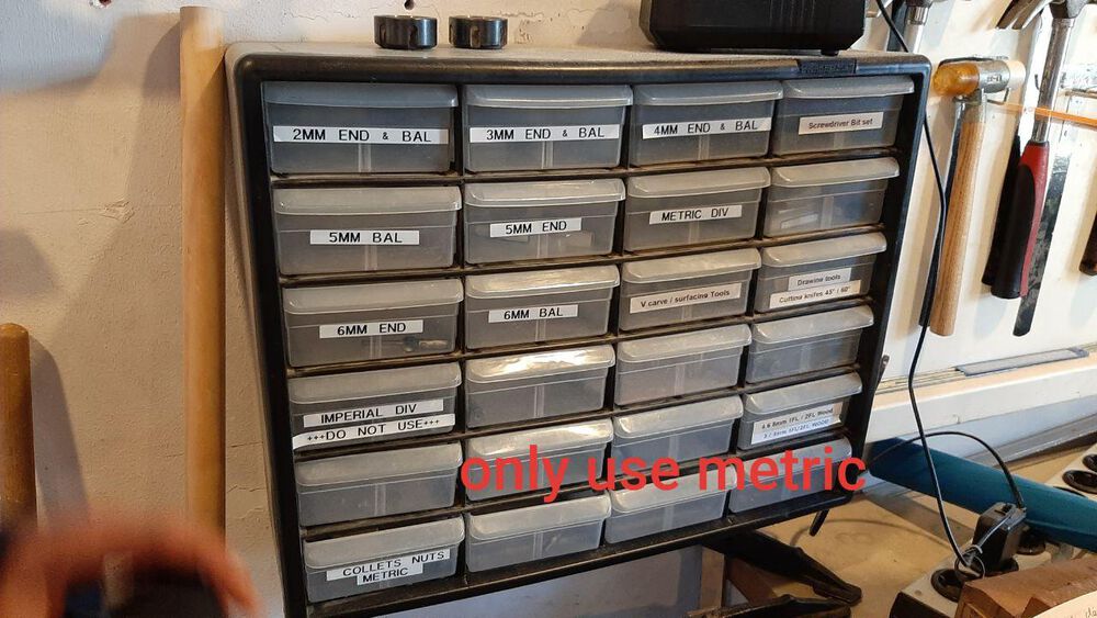 |
| 3 | Find the right mill for a collar, the nr on the collar correspondents with the mill nr | 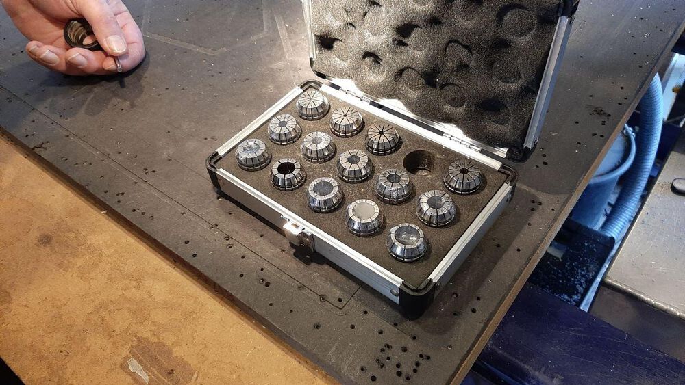 |
| 4 | 6 is the Mill size, 25 is the nut size | 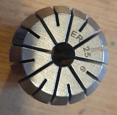 |
| 5 | First press the collet in the Nut, then put the mill in | 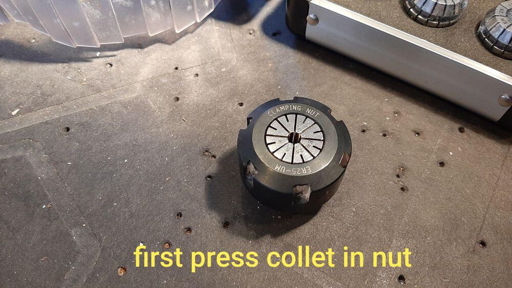 |
| 6 | Tighten the NUT, MILL, COLLET using the tools | 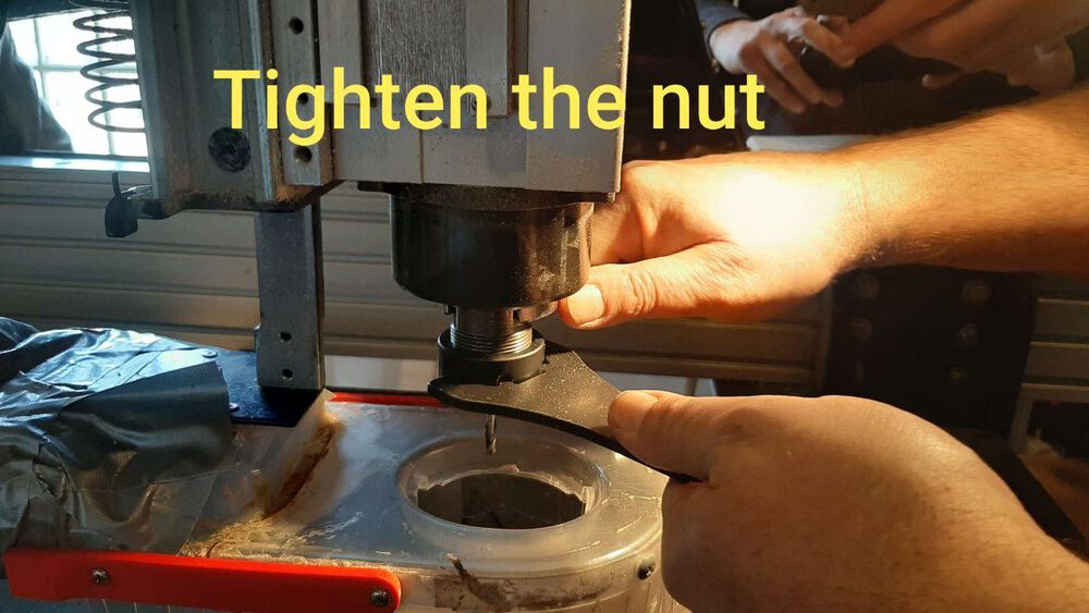 |
| 7 | Put the tools back where they belong | 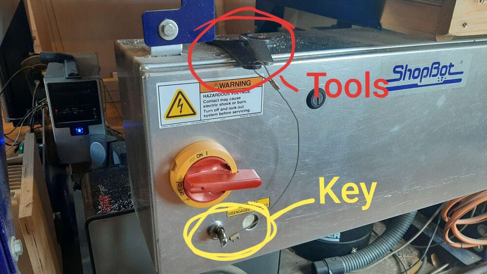 |
5. Fusion 360 - Designing for the CNC milling machine
I have only 8 hours for the design & get the files ready to be milled… So here we go!
Dogbone Joints. Inspired me to make the dog-bones a part of the design. I dropped this because I was running out of time. Frontier Design inspired me to make a stackable system with different sizes. From a spiral design point of view I could start wit simple elements. But all should be parametric, so not the simplest I can Do.
| 1 | Create a parametric handle was a lot of work | 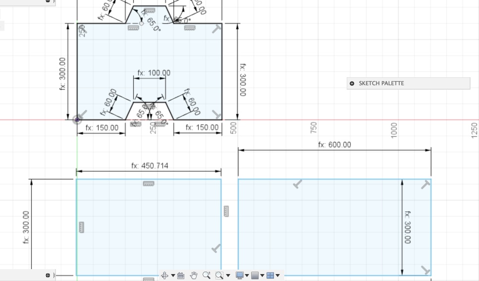 |
| 2 | I had to use co-sinus to get the math right | 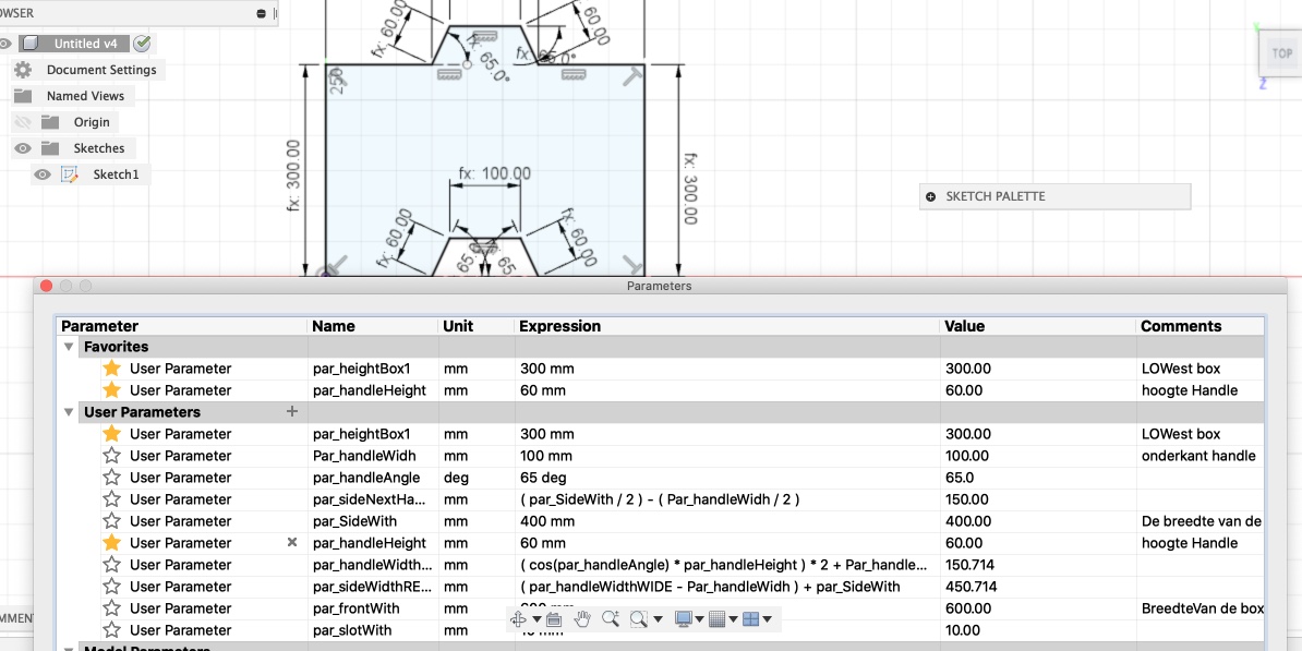 |
| 4 | When entering other dimensions, the handle rotated a bit. | 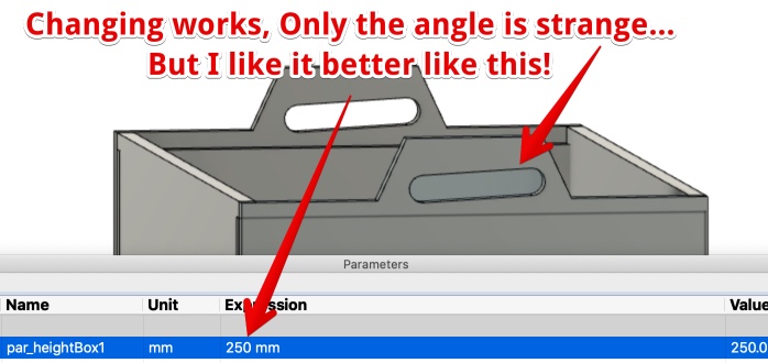 |
| 5 | I added fingers for the pres-fit in the 3D environment | 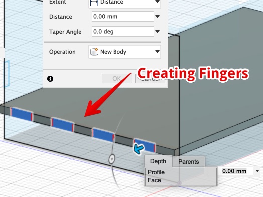 |
| 6 | Used the Combine > Cut procedure to take the fingers out of the fitting material | 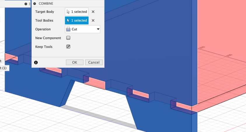 |
| 7 | When adding appearance, some mistakes became visible | 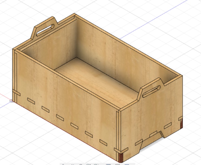 |
| 8 | Most of the time only loose parts, caused by the combine command | 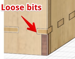 |
| 9 | Use the combine > Join commands to fix the loose parts | 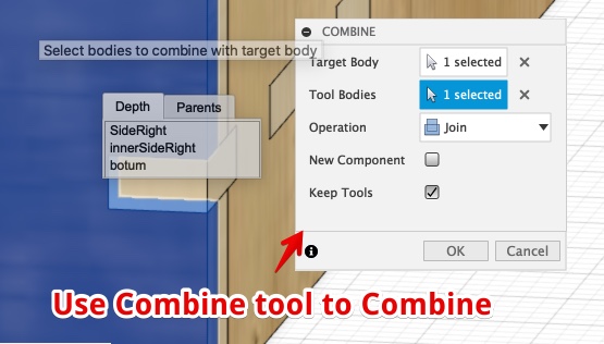 |
First I create all the panels in one sketch in Fusion 360. When ready I wanted to add fingers.
I found this video explaining how to make parametric finger-jonts in fusion 360.
I copied all the sketches to 3D placing all the sketches on the face of the 3D object. When all the panels are ready I stared to make the Fingers. When Some where ready I tried to export the separate panels to 2D. Export As DXF.
But this was impossible! I could only export the sketches, and the sketches doesn’t contain the improvements/cuts/fingers. All is made in 3D!!
I really panicked since time was running out. I Hit Google but all manuals just gave me a way to OR, create 2D sketches and send those to CNC.
A few hours I banged my head against the 3D wall.
Than I thought I could try to trace the faces as a sketch, This would result in a failure but still better than nothing. Than I started searching for ‘convert faces to sketch’. I’m not the only one, It is not a feature but from a face you can create a sketch simular to the face!
THANKS: to this post explaining how to export to dxf via the face of 3d
My global evaluator (Yuichitamiya) gave me antother fine tip I really want to record for future reverence:
- Use Shaper Utilities to export to SVG.
- This extension is for Shaper Origin.
How to export Fusion 360 to DXF
- Click an face of an object en ‘create sketch’
- Finish
- Rename this new sketch
- Click on sketch (layer) and ‘export as DXF’
Mistakes/mental notes I was really stressed during the design because of the unclear design process and the extreme timepressure. So I made mistakes and really froze from panic two times that day.
- I made All drawings in One sketch
- I wanted to finish the sketches 2D
The result 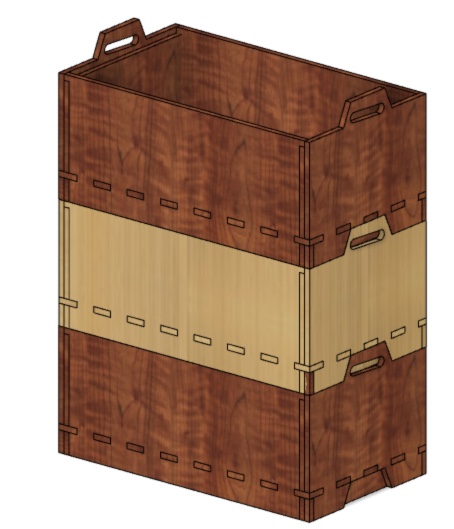
6. Illustrator
| Since the tests we did with the group assignment showed the size of the wood after cutout (outer line) is 0.8 to 1.1 mm bigger. | ||
| 1 | I made all inner diameters of fingers 0.8 mm bigger. I hope this will be snug enough and sometimes even press fit. | 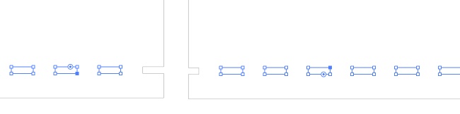 |
| 2 | I did’nt like the finger hole to be so close to the edge, so I moved it | 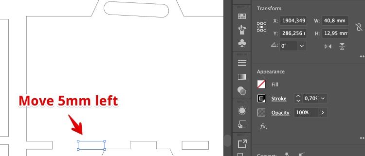 |
| 3 | And I had to move all the fingers 5 mm too | 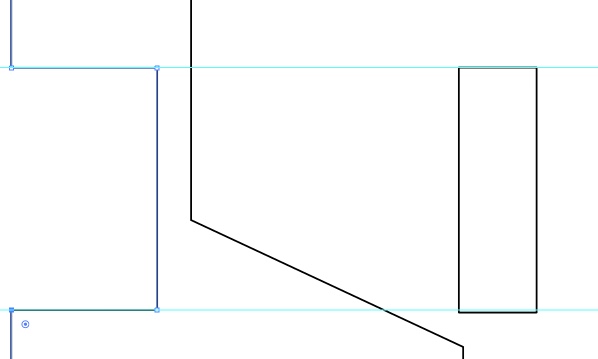 |
| 4 | Save the file as Illustrator 8 | 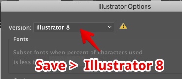 |
Mistakes/mental notes
- I tried to open
- I wanted to finisch the sketches 2D
The result 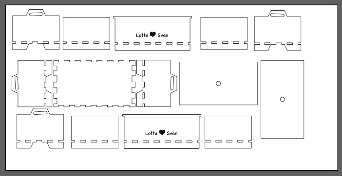
7. VCarve Pro - Prepare a file for the Shopbot software
| 1 | Open the Ai file (I used AI 8) | |
| 1a | Double check the dimensions of the file | |
| 2 | Job setup: Set material Thickness, Dimensions, Material Z must be on top. No offset. XY datum position, lower Left. Modeling resolution is only the way you view a file | 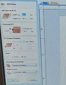 |
| 3 | Press OK, the panel will get to the right. set: Z zero = top. XY Left bottom. De-select use offset | 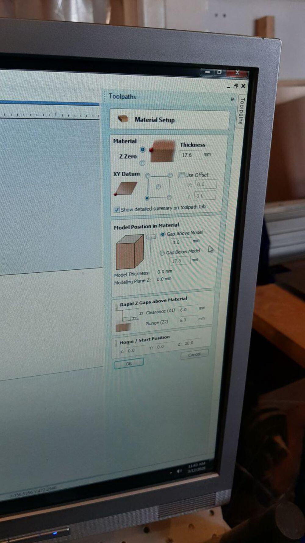 |
| 4 | Click on a path (in your drawing and configure the tool-paths). Start dept = 0, Cut dept is material thickness + 0.1 mm!. Click “Select” | 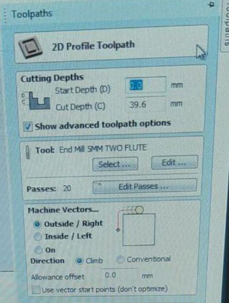 |
| 5 | Select the ‘End Mill 5MM two flute’ | 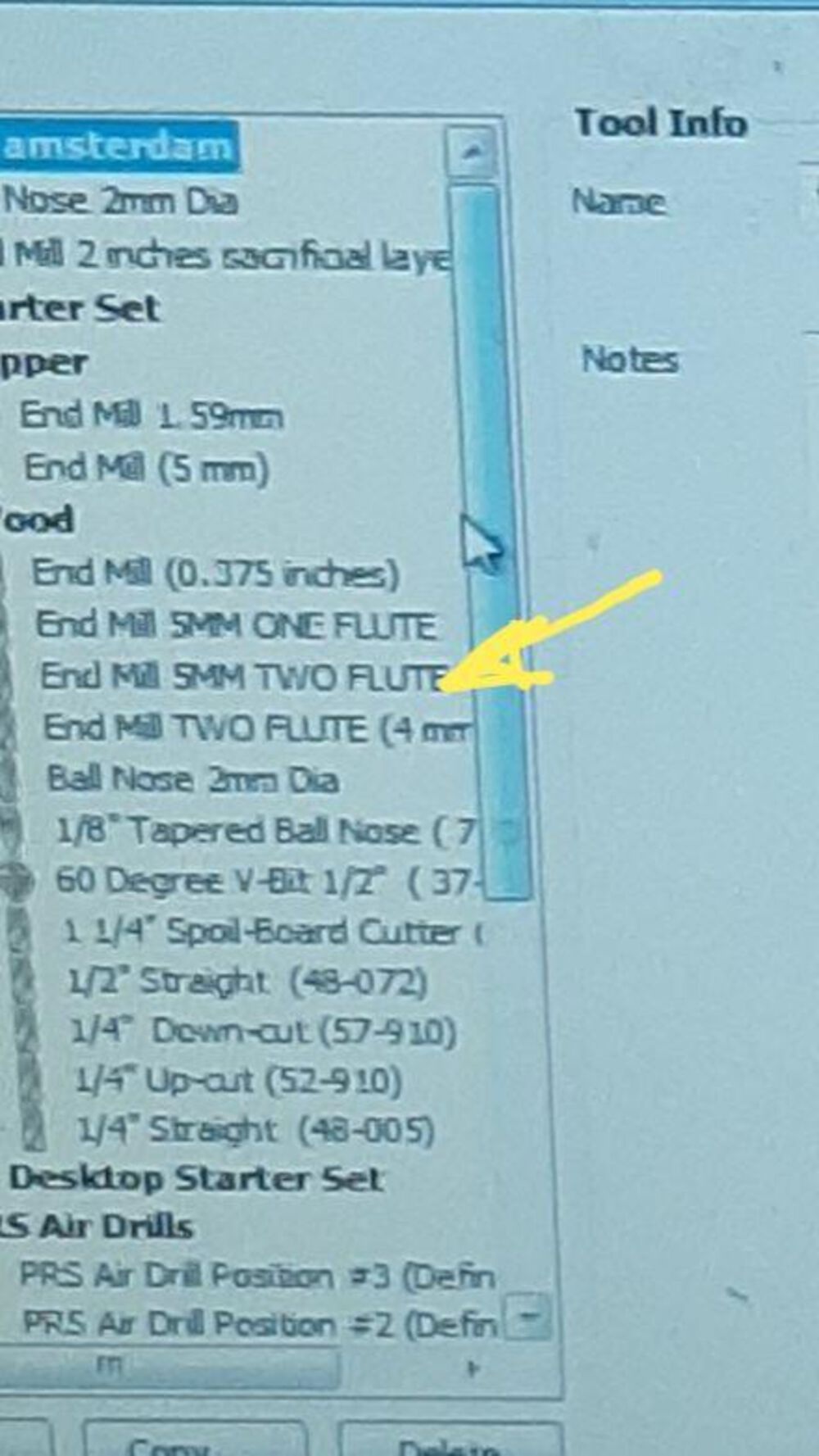 |
| 6 | Set passes to 6 | 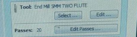 |
| 7 | Machine vectors settings | 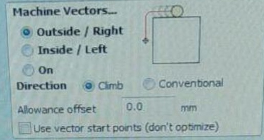 |
| 8 | Add Tabs to the tool-path, Click on your drawing, click again to remove | 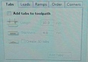 |
| 9 | Press Calculate when ready |
Shortlist (for my next time)
- Open file
- Set up dimensions (smaller than your actual material to be save)
- Create separate tool-paths (inner cuts, outer-cuts and cutout)
- select path (Profile etc) for the same toolpaths
- choose ‘cut’ etc
- Drill settings
- Add Tabs
- Name toolpath
- Repeat for all toolpaths
- Calculate toolpath
- Add dog-bones - Fillets (icon in the Edit Objects - left panel)
- Calculate every tool-path again
Mistakes/mental notes
1 I forgot to move the fingers of the inner panels 
8. ShopBot
| 1 | Insert the spindle | |
| 2 | Turn on the Shopbot with BIG turning swith on the side | |
| 3 | Open the Shopbot software and strike ‘k’ on the keyboard. | |
| 4 | Manually move the mill to 0,0 material (zero X = 0 and the Y = 0, lower right corner) | 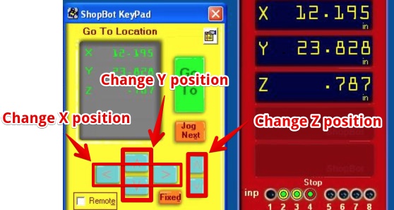 |
| 5 | Make a picture | 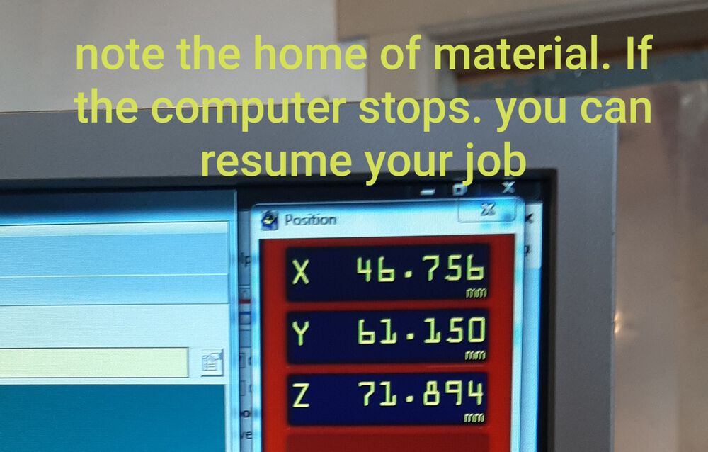 |
| 6 | Set xy zero: [Z]ero > ‘Zero 2 Axes [X & Y]’ | 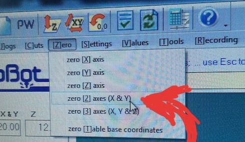 |
| 7 | Move the mill to the center of the material. Put metal plate under the Mill (not turning!). | |
| 8 | Automatically Set Z zero: [C]uts > ‘C2 - Zero Z axis w/ ZZero Plate.’ | |
| 9 | Remove the metal plate and check if the machine is free (around and on the workspace) | |
| 10 | Check if the Skirt is fixed (can it move up or down?) | |
| 11 | Turn on the Vacuum (Knob next to the green light bulb & turning Knob at the front of the CNC) | |
| 12 | Turn on the spindle with the key (attached to the tools) | |
| 13 | ‘Open file’ - Find your toolpath | |
| 14 | Double check all and press Start, Keep your hand above the spacebar for the first minute | 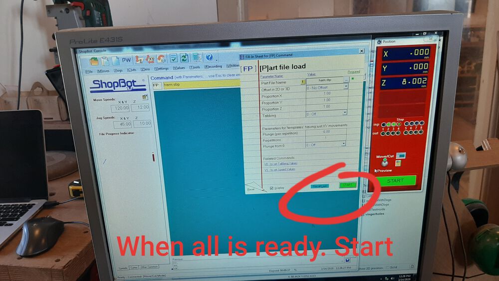 |
Change shopbot settings during operations
You can change the moving speed during operation
| 1 | If the Mill is up, press ‘SPacebar’ on keyboard | |
| 2 | Click ‘Enter Command’ in the popup | |
| 3 | Press ‘k’ on the keyboard | |
| 4 | Click the fields and change settings. I changed to this: | 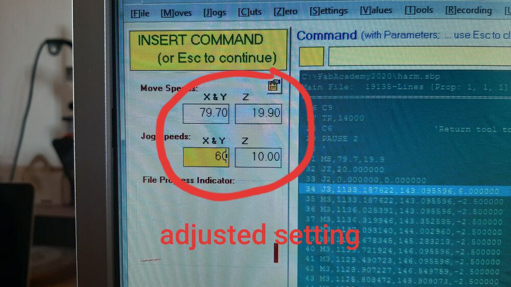 |
| 5 | Pres the ‘esc’ button | |
| 6 | Click “resume Job” in popup menu |
9. The Final result - the panels
| 1 | All the panels | 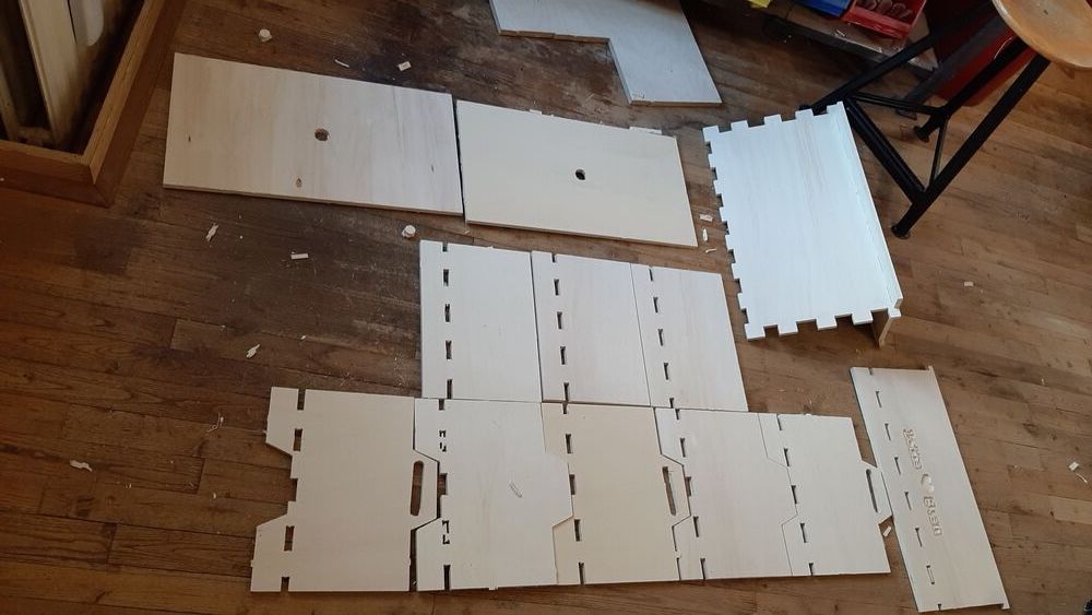 |
| 2 | I didn’t sand the panels. My plan was to hammer them in and do the sanding after putting it together. It was made to fit, not to sand… | 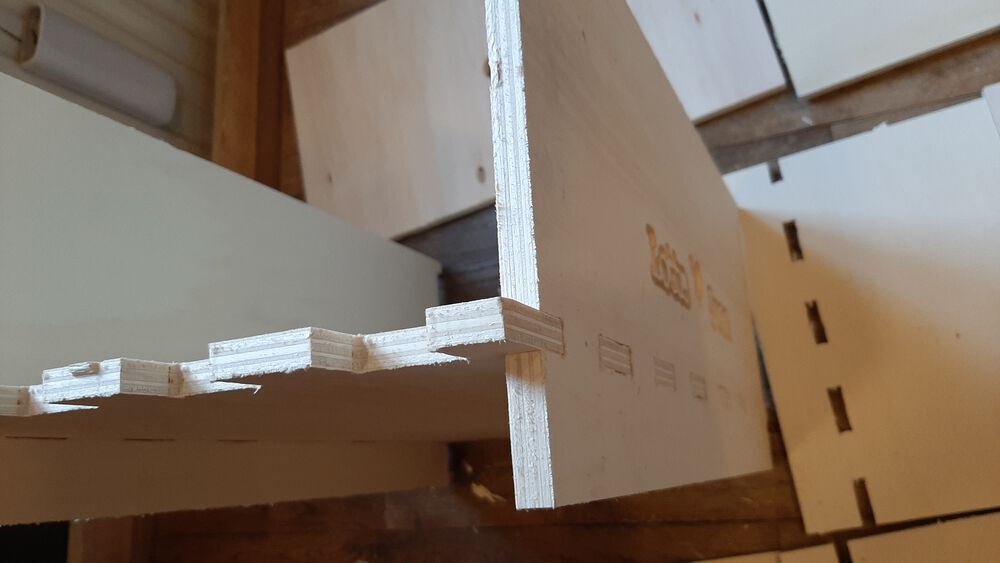 |
| 3 | The fingers on both sides did’nt fit. I changed the fingers in illustrator, but forgot two panels | 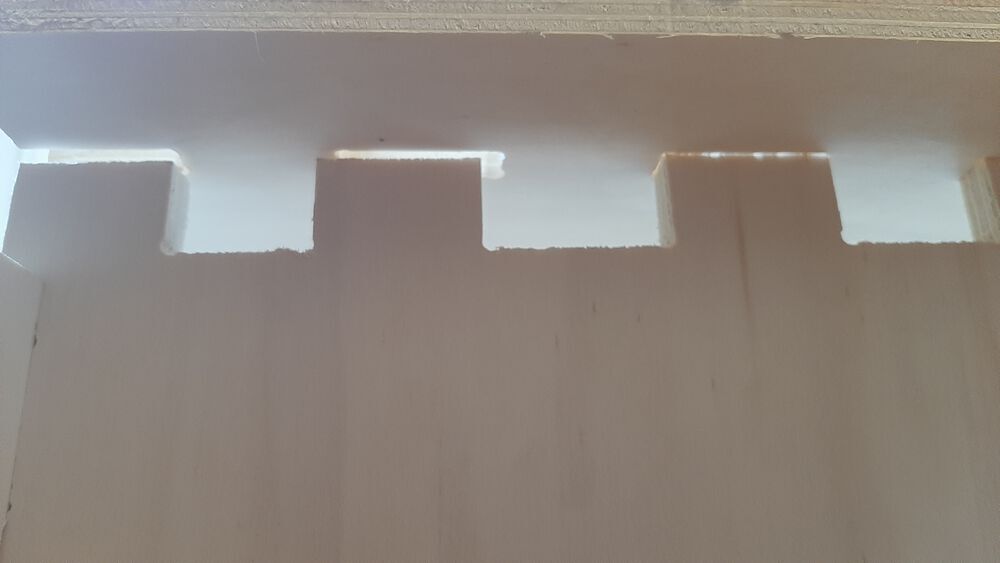 |
| 4 | So I needed to take some of the finger to fit the panel. | 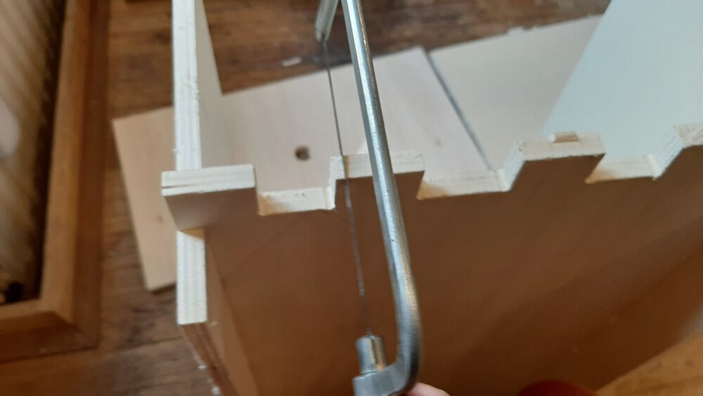 |
Lessons learned:
- Don’t change the design in illustrator, I will make mistakes
10. The Final result - putting it together
| 1 | Mistake 1, love text on the inside | 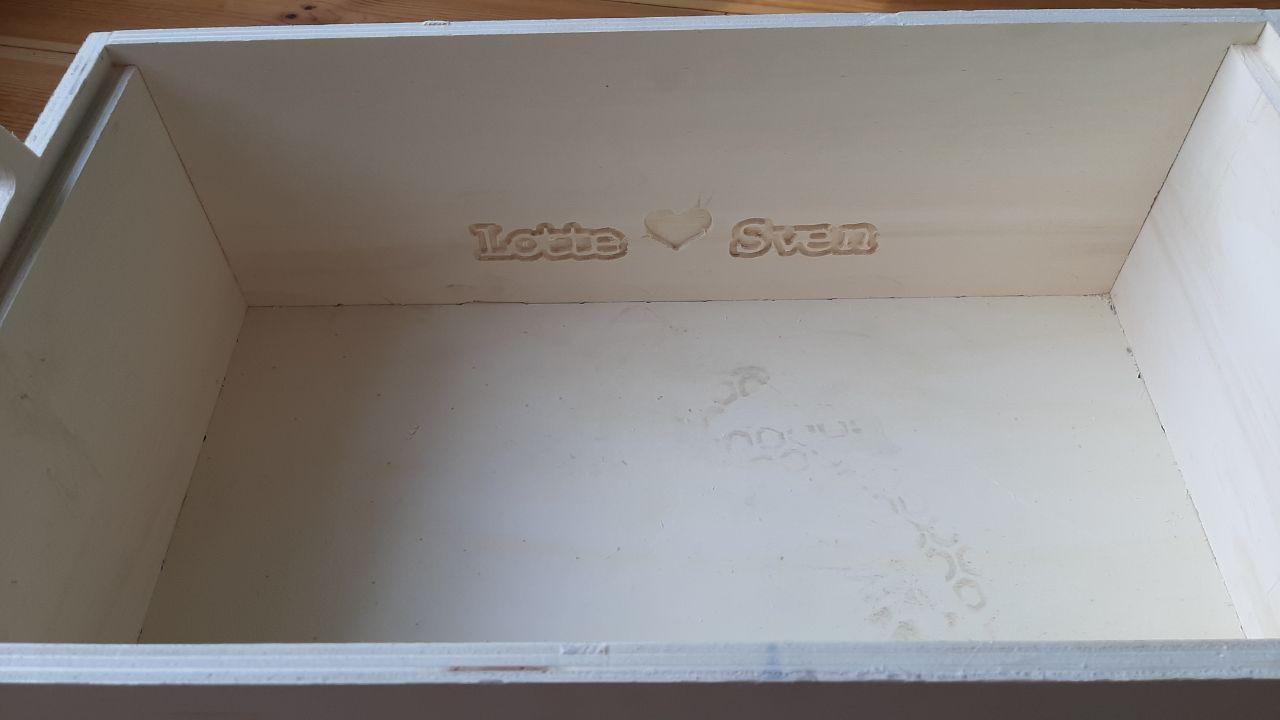 |
| 1 | The top panel fits like a glove | 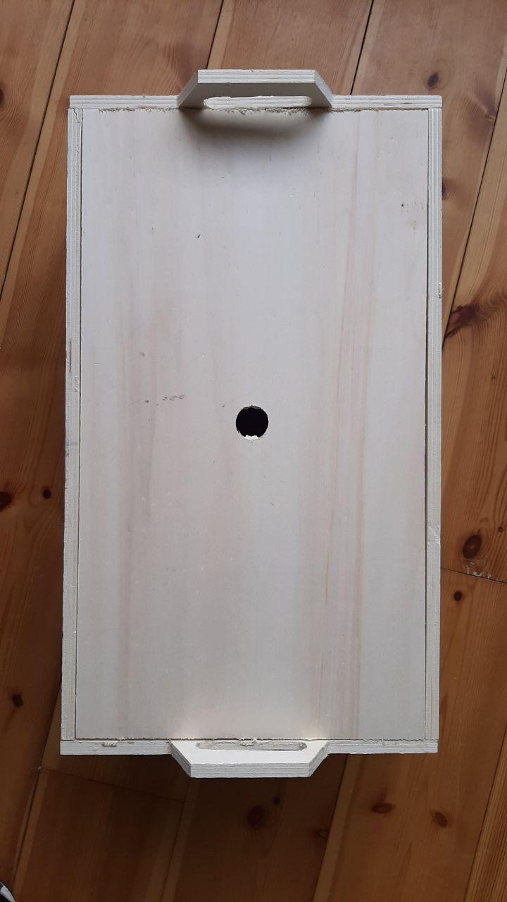 |
| 1 | This should fit, probably It didn’t since I refused to sand | 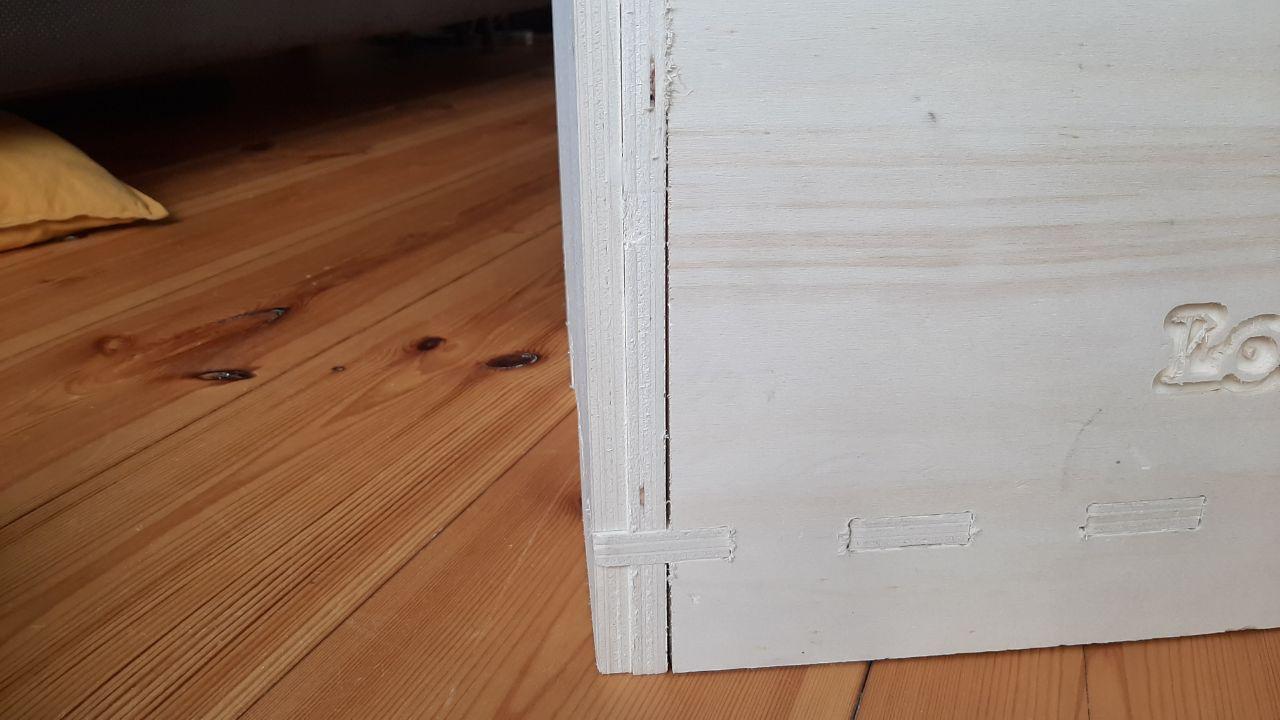 |
| 1 | Mistake 2, the misplaced finger. some damage from hammering it without sanding. | 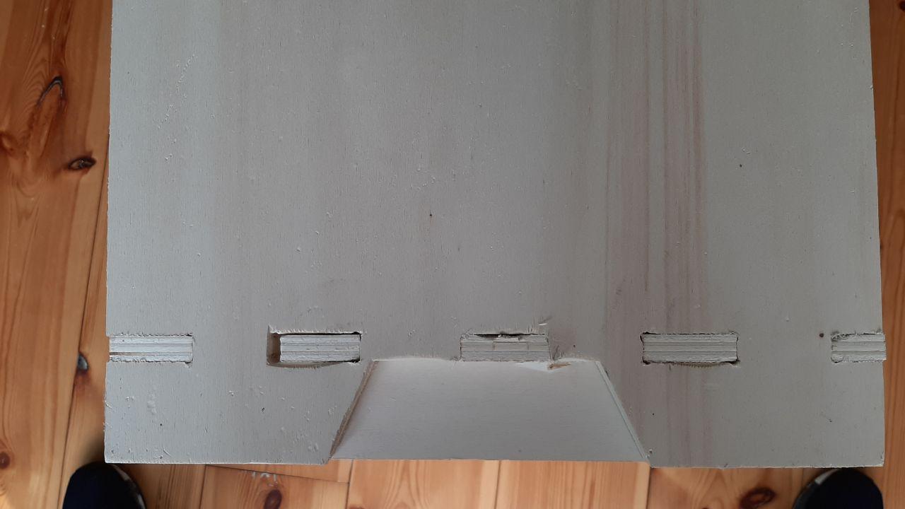 |
| 1 | Bottom is a decent fit | 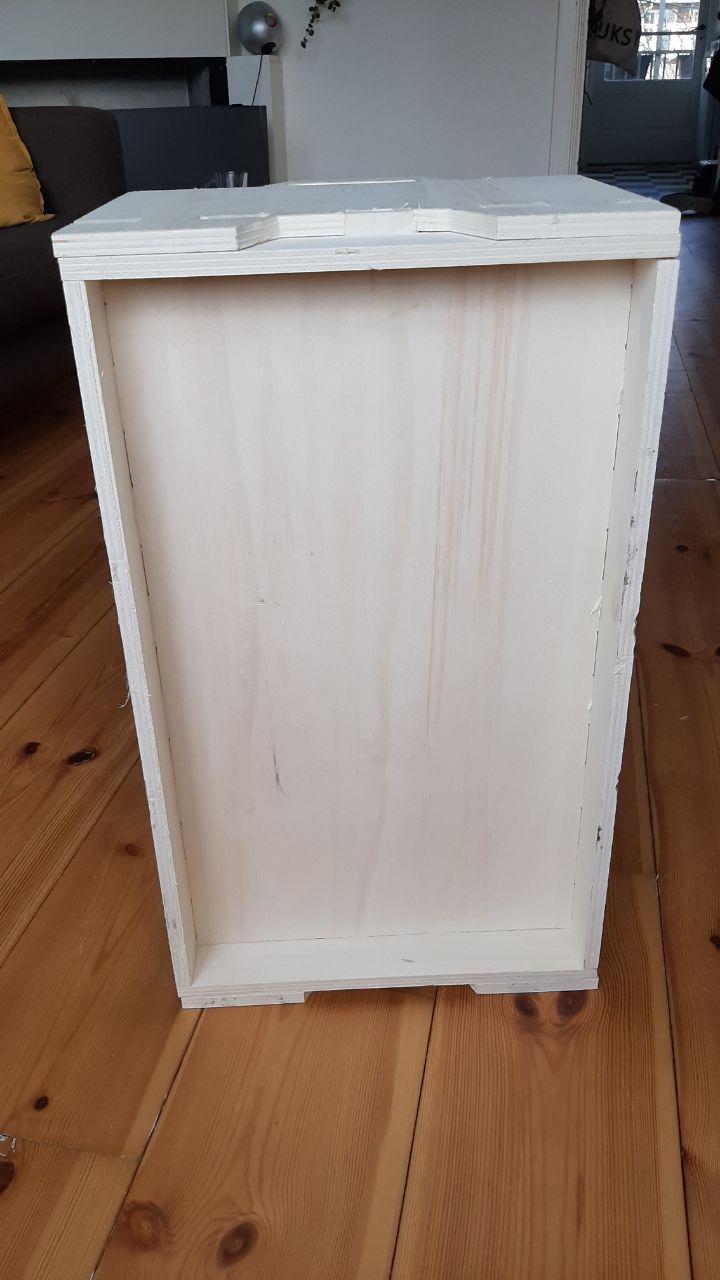 |
| 1 | Final result, some mistakes and really rough without any sanding | 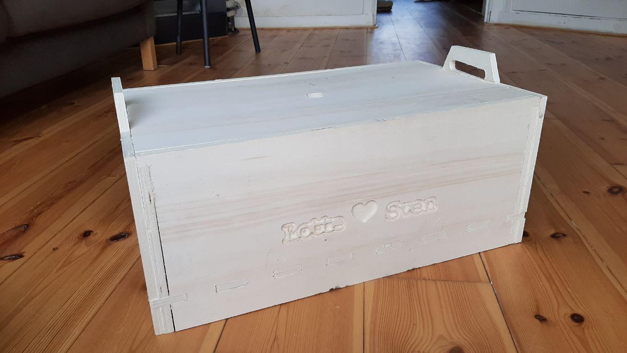 |
Files & conclusion for this week
The files
- Fusion Parametric file
- 3D file
- DXF exports from Fusion. One DXF per panel
- Illustrator file, with all panels
- VCarve Pro save .crv file (too big for FabAcademy)
- Exported VCarve pro file .sbp
Biggest Mistakes and lessons this week
- Don’t start if you don’t know what your process will be. Same mistake as last week!
- Don’t try to make a CNC design in 8 hours if you never did it
- Check the fingers before printing
Wat I really liked
- The parametric designing, and the 3D design in Fusion was fun
- Putting the box together was fun to do, Hammer time!
- I really had fun about my mistakes, BIG mistakes are more fun!
My concerns
- I did not handle the stress very well.
- Will I be able to use the (almost unusable) software on the CNC machine next time?
- I made nothing in line with my final project.