8 - Embedded programming
This week we will practice our ‘Embedded programming’ skills. I will test different toolchains on different Microcontrollers. A toolchain is a set of tools that compiles source code into executables that run on microcontrollers. Next to that I will try to read datasheets of microcontrollers and datasheets in general.
How can I use this in my final project?
- A WiFi Microcontroller will be the heart of my project
- I need read datasheets to be able to find
- High-current components (so read datasheets) to drive my Nichrome wires
- A way to drive 30+ wires with WiFi Microcontroller (only a few outputs)
The steps for this assignment
- 1. Group: Compare different work-flows (toolflows) for different microprocessors
- 2. Read datasheet? What is the ESP8266?
- 2. Connect a random ESP8266 Module
- 3. Program NodeMCU with Arduino
- 4. Program a NodeMCU with VSCODE
- 4. Program a NodeMCU using Platform IO VSCODE and
- compare: Arduino IDE VS PlatformIO VS VScode-Arduino
- Create a basic code to drive my 36 heat wires (final project)
- I Finished this assignment in week 6, 9 and 10:
- Final conclusion for this week
1. Group: Compare different work-flows (toolflows) for different microprocessors
read all about this group assignment
2. Read datasheet? What is the ESP8266?
I Used the NodeMCU (with a ESP8266 on it) in my lessons, but never had a ESP8266. In the datasheets I found info and it is available in the grouppage, but this HackAday page explained the ESP8266 is not one chip it is the ESP8266EX, A flash Memory and some components. Most ESP modules we have cover the two chips. Together they are revered to as ‘MOD’ i think from Module…
I found several Flash chips next to the ESP8266EX. I looked up the datasheets for the Flash memory
Different Flash Memory chips in the ESP MOD. Below some I found.
| 1 | With the BQ25Q80ASSIG Flash module, with 1024Mbyte. Datasheet | 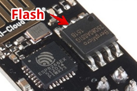 |
| 2 | AT25080B, with 1024Mbyte. Datasheet | 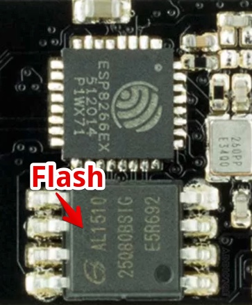 |
| 3 | PN25F08 datasheet, 1024Mbyte, Voltage 2.7~3.6V | 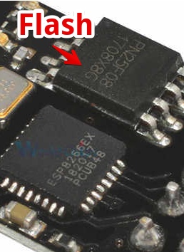 |
| 4 | The ESP8266 MODule, Wikipedia states these modules should be called ESP-01 to ESP-14. The major difference is the Flash memory, the LED, and the antenna | 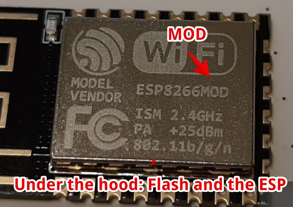 |
Mistakes/mental notes
- I always assumed the ESP8266 was a chip, but a ESP8266MOD is not the same as a ESP8266 chip. The Best is to rever to the module as ESP-01 to ESP-14 depending on the module
- There are a lot of different Flash memory modules, I can’t see big differences between the specs
2. Connect a random ESP8266 Module
So this is my quest to do so. I used this instruction to get me started. Program ESP8266 module
| 1 | In the goody bag from the Waag Hardware i found this module | 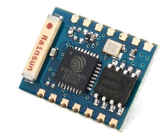 |
| 2 | I looked up the datascheet | datasheet ESP8266EX |
| 3 | In the groupassingment I made a full overview of all the specs, but for now I had to worry about the voltage, max is 3.6 | So if I connect It to my FTDI board is will be damaged |
| 4 | since I had no access to the Waag and the Lab Power supply I found an 3v output on the NodeMCU. | 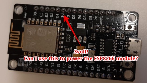 |
| 6 | This is the overall plan | 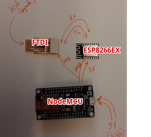 |
| 7 | U used the drawing from my previous week to find where I should connect the ESP module | 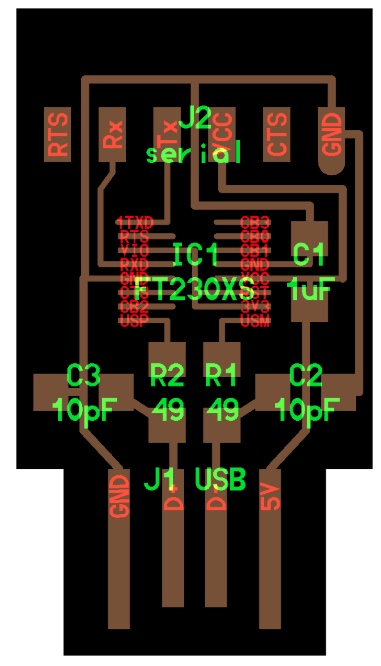 |
| 8 | Via This hackAday page I found the schematics, I have to use a NodeMCU as a voltage regulator ;-) ] | 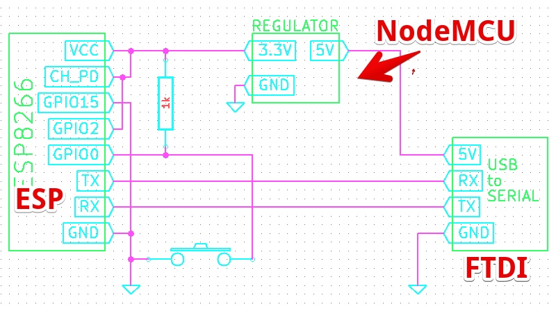 |
| 9 | This is how I should be able to connect the different devices | |
| 10 | This instructable website was pretty clear, you need TWO buttons. So I doubt the Hackaday solution… | 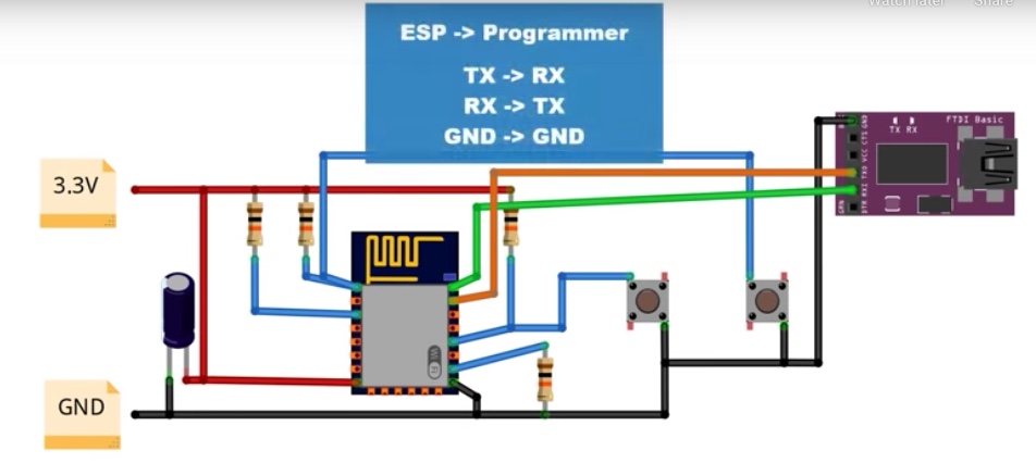 |
| 11 | Since I have no access to buttons (due the Corona) my first try to do it the ‘Easy way’ using an NodeMCU found on this page | 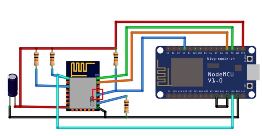 |
| 12 | But the ESP module in the drawing is different from the one I have, I looked up the connections of the ‘Rainsun’ It turns out it is a ESP-03 | 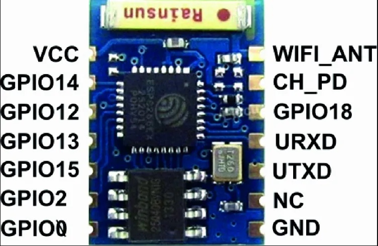 |
| 13 | In Arduino I need to enter the size of the flash | 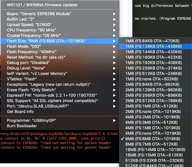 |
| 14 | It was Hard to see, and I had to test different variations, But I found the datasheet of the 25Q41. I found the [datasheet] and the specs: 4M-bit Serial Flash, 512K-byte, 256 bytes per page | 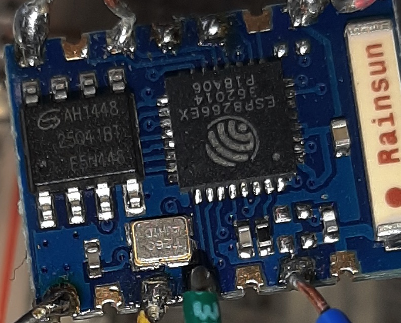 |
| 15 | I used these settings in Arduino. But my empty sketch was not willing to upload “esptool.FatalError: Failed to connect to ESP8266: Timed out waiting for packet header” |  |
Mistakes/mental notes
- I thought a ESP8266 (module) was a chip, but it is a complete circuit with two chips
- Since I programmed a NodeMCU before I thought it was simple to program a ESP8266 Module
- There is a lot of difference between the ESP8266 modules, this is why they are revered to as ESP-01 till ESP-14
The result 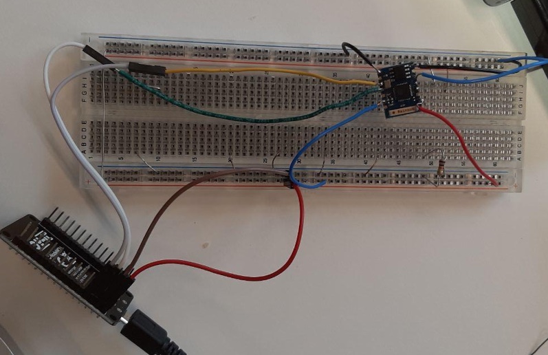
3. Program NodeMCU with Arduino
- install Arduion IDE Download Arduino
- downdload And install the driver CP210x USB to UART Bridge VCP Drivers
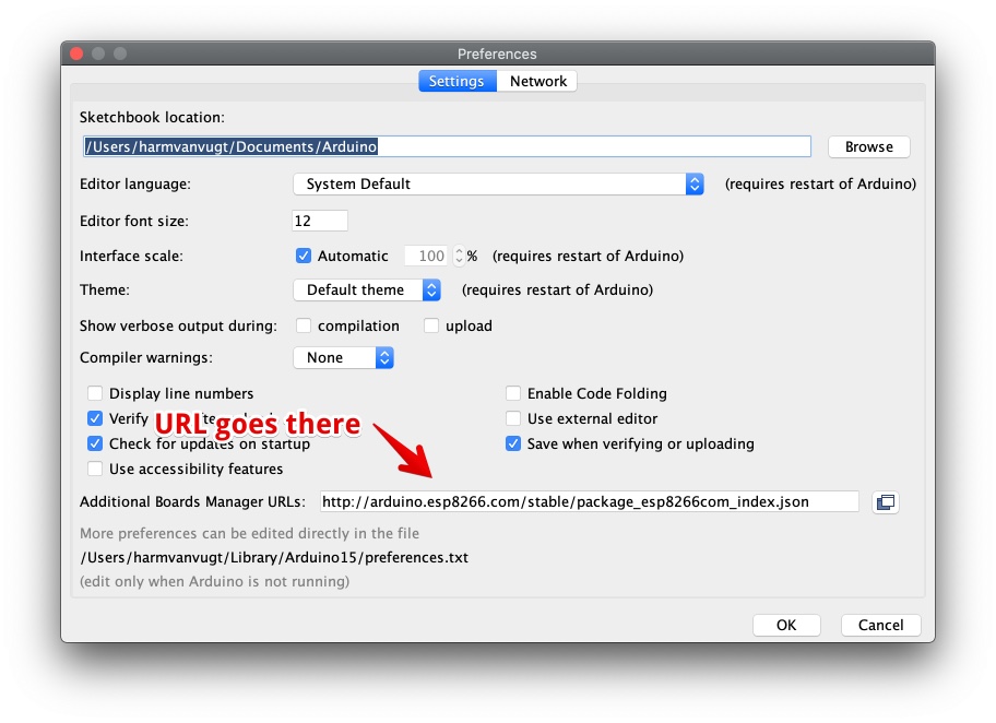
- Add the Esp8266, File - Preferences. At “Additional Boards Manager URLs” paste http://arduino.esp8266.com/stable/package_esp8266com_index.json. Klik OK
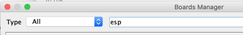
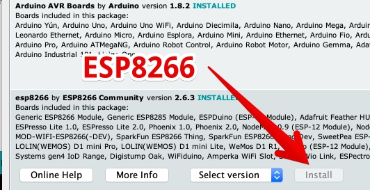
- Under tools > Boards > Board manger. Search for “ESP”
- Install ESP8266
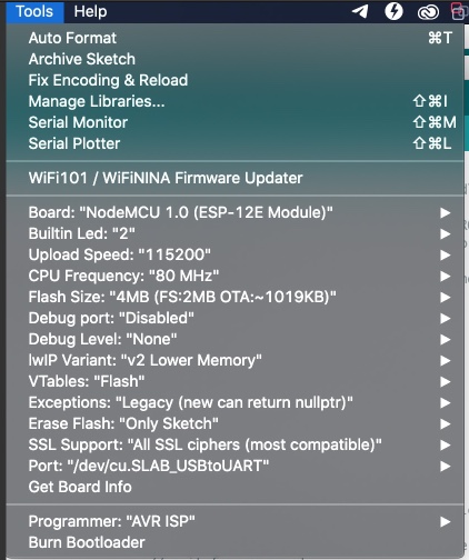
- Plug in the board in your USB and use these settings:
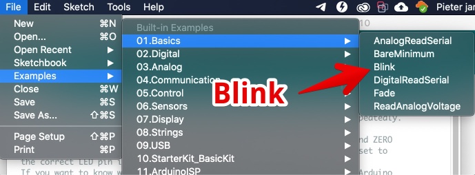
- Go to File > Examples > 01. Basics > Blink
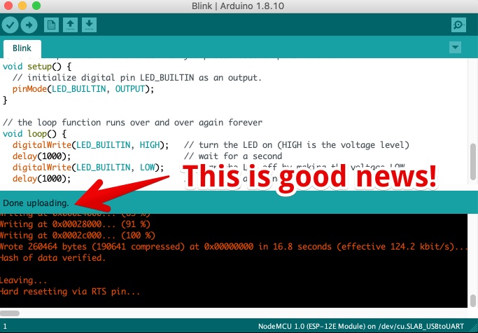
- Upload the code (press arrow/ CMD-U on Mac)
- If all goes well, you will see ‘Done uploading’ in the Arduino IDE and the LED on the board will blink.
Mistakes/mental notes
- The Arduino platform is really easy to set up
4. Program a NodeMCU with VSCODE
- I Downloaded and install Visual Studio Code
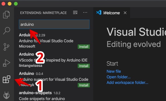
- I followed the instructions from Nick Raboy and added the Arduino via Extensions
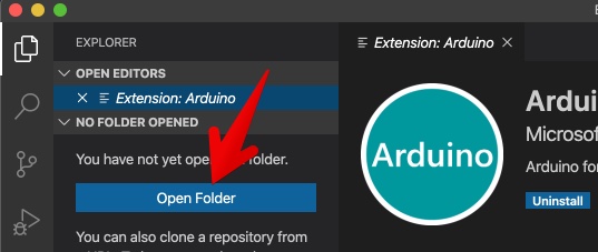
- Open the folder where you would like your Arduino code to be
- I then opened the example blink code from the Arduino IDE and pasted in a new file in VS-Code
- I expected the IDE to recocnice the code as Arduino, so with the colored text in the example video. But my code was white
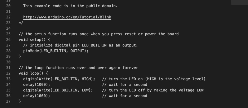 This is the code in the video:
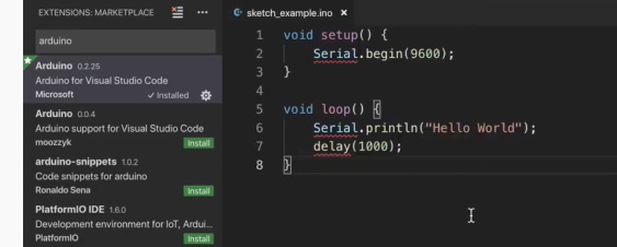
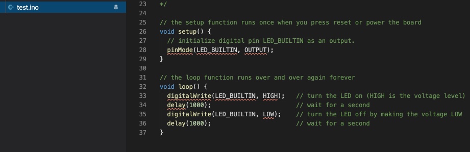
- Than I changed the name of extension to .ino (like the example file), and all looked fine:
- Now some configuration: press ‘CMD - Shift - P’ for the commands palette and type ‘Arduino: Board configuration’
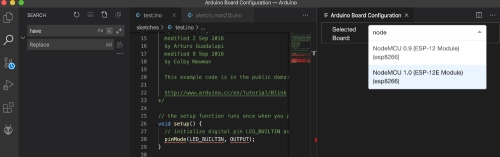
- Now I have two options, NodeMCU 0.9 and NodeMCU 1.0. This week reading datasheets is one of the learning goals I tried to make sure I picked the right one. I could not find a ‘datasheet’ for nodeMCU. This Post compared the two and the 1.0 should have ESP-12E where the 0.9 should have a ESP-12. ‘E’ stands for ‘enhanced’. Both boards got a ESP-12 4MB flash. I read this post dedicated to compare NodeMCU’sbut was merely talking about the form factor (0.9 is wider) and explained both boards are pretty similar. But my board is the less wider one. Not really a datasheet…
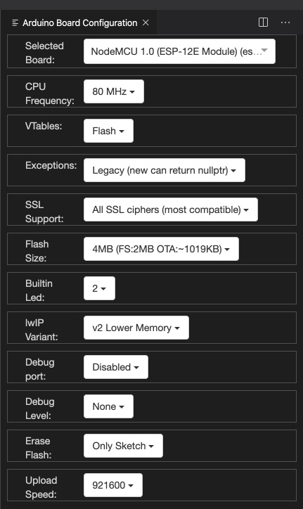
- I selected the 1.0 version. It came up with all those options, I just let them like the where.
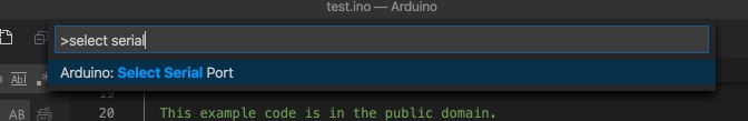
- Now select Serial Port using ‘CMD - Shift - P’ and ‘Arduino: Serial port’ this didn’t work. Just nothing happens if I execute this command.
- When restarting VS code I got this warning:
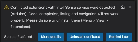 And I disabled all extension to be sure. But still the ‘Arduino: Serial port’ command gave no results
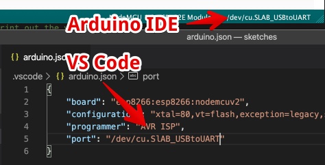
 - I tried to setup the programmer, since this was not set. I looked in the working Arduino IDE to see what was selected. It was AVR ISP.
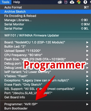 . Maybe this should be done before I can select the serial port…
 - This Github Issue “Clicking Select Serial port does nothing” explained me I’m not the only one with the problem. And I should look at the Json Arduino configfile.
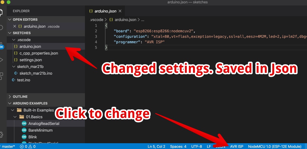 In this file all the settings are stored.
 - I coppied the settings from the Arduino IDE and entered these in the VS Code IDE
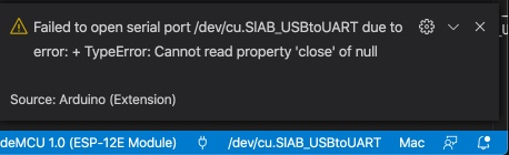
- And I got the Error message “Failed to open serial port /dev/cu.SlAB_USBtoUART due to error: + TypeError: Cannot read property ‘close’ of null”. It looks like manually adding the Port was not a success.
- A lot of users on the Github issue tracker still complaining it doesn’t work. The workaround should be downgrade to the version before jan 2020. I’m going to test this when I have access to WiFi. (working from Hotspot now…)
Mistakes/mental notes
- I Spend far to much time getting this toolpath to work, It feels like a waste of time
4. Program a NodeMCU using Platform IO VSCODE and
Platform IO was mentioned by Jules (inter at de Waag). On the Platform IO website they describe it as “PlatformIO is a cross-platform, cross-architecture, multiple framework, professional tool for embedded systems engineers and for software developers who write applications for embedded products.” And it received the “best Software and Tools in the 2015/16 IoT Awards.” since my final project is a IoT project, so it is very interesting to test. Here we go!
- Download and install the “PlatformIO IDE” via the website
- I followed this video manual to install it. It was pretty strait forward.
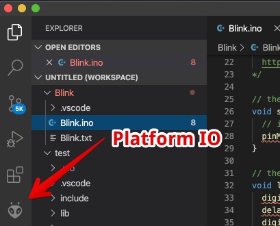
- After installing you should see the ‘Alien’ in the left bar of VS code
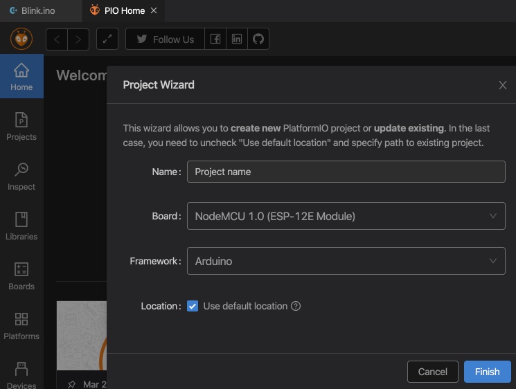
- Use these steps to create a new project
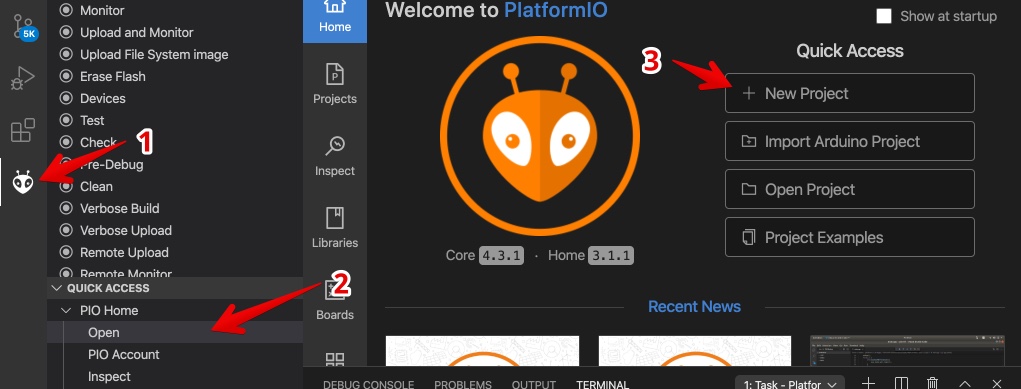
- The wizzard guided me trough the steps
- to upload a sketch use CMD-shift-P and choose upload
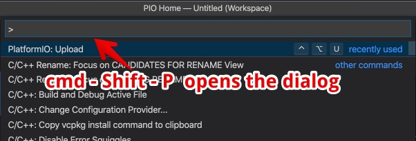
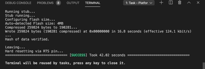
- The upload works!
- But the LED on the NODEMCU is not blinking…
- I got an error message while opening the blink code, this could be the reason
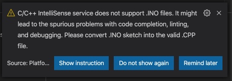 I followed the “Show instructions” link they lead me to the docs website of IO
 - It looks like PLatform IO does not support Arduino files. Only C++ files, i thought they are the same…
To use Platform IO I should change the Arduino Files to convert it to proper C++:
- Add
#include <Arduino.h>at the top of the source file - Declare each custom function (excluding built-in, such as setup and loop) before it will be called.
- Rename the file to .cpp (not .ino)
- so the new file is called Blink.cpp and looks like this
#include <Arduino.h>

void setup()
{
  // initialize LED digital pin as an output.
  pinMode(LED_BUILTIN, OUTPUT);
}
void loop()
{
  // turn the LED on (HIGH is the voltage level)
  digitalWrite(LED_BUILTIN, HIGH);
  // wait for a second
  delay(1000);
  // turn the LED off by making the voltage LOW
  digitalWrite(LED_BUILTIN, LOW);
   // wait for a second
  delay(1000);
}
- Upload the ccp file. The shortcut is ctrl-alt-U
- Blink Works!!
Mistakes/mental notes
- I thought Arduino ‘language’ was the same as C++, it is not!
compare: Arduino IDE VS PlatformIO VS VScode-Arduino
| Test | Arduino IDE | PlatformIO | VScode-Arduino |
|---|---|---|---|
| Download & install | 10 minutes | 1 hour | 30 minutes |
| Upload first code | 30 minutes | 5 hours | never succeeded |
| Upload Blink | 23.58 seconds (in debug screen) | 23 seconds (measured by hand) | never succeeded |
Conclusion
To work with PlatformIO all Arduino files have to be changed to clean C++. Since I plan to use a lot of excising code from examples (this is the only way to get it done in time) I leave PlatformIO for now. If have to much time it is definitely a cool tool to start working in one day…
Create a basic code to drive my 36 heat wires (final project)
For my Final project I want to heat 12 wires for one day and I want to display 3 days forecast. I need to get the forecast from the internet. I have build an API to display the forecast in the past, so I have it in JSON. And I need to get this data to the outputs, where I only have a few PIO’s on the ESP8266.
So I looked for ways to drive multiple outputs. Well described in my. I found a multiplexer in a Kit a took from my University just before it closed (Due SARS2). It is the CD74HC4051-EP With Trough-hole pins.
- I looked on the internet for examples and found some examples. They basically explained me that I have to connect 3 outputs to the multiplexer, and the 8 legs of output changes according to this.
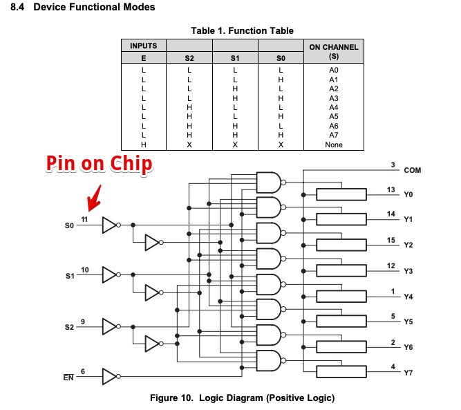
In the [datasheet] I found a schematics that helped me wiring it up
Than I looked up how I should connect the voltage. It was on the top of the Datasheet
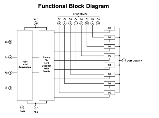
- VCC is + voltage, But what is VEE? This post on All About Circuits explained it. Sort of…
- VCC = Cathode
- VDD = Drain
- VSS = Source
- VEE = Emitter
But this didn’t help me so much to know how I should connect my VEE leg?
I searched in the datascheet for ‘VEE’ and i found this table
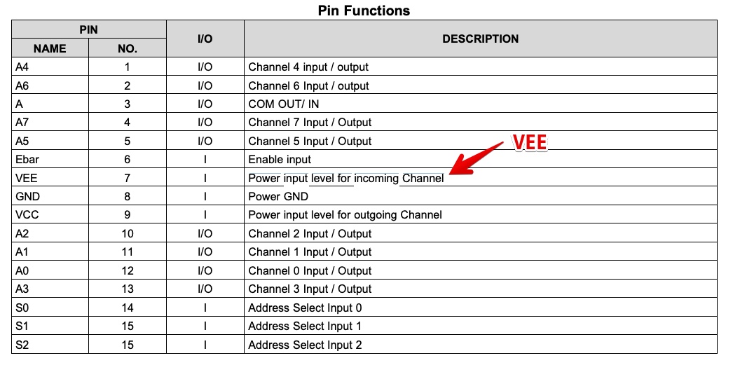
- Combined with the Functional Block diagram. I assume VEE = should be the same voltage as the voltage on S0, S1 and S2
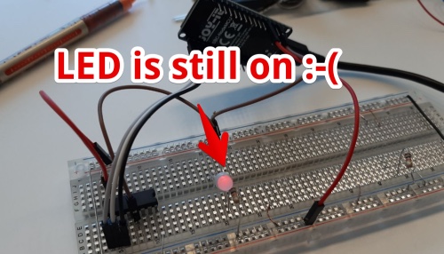
- I connected a led (via Resistor to Y0) to the Multiplexer and The led was ON.
- Now I tried to switch off the led using of. Using the function Table from the datasheet
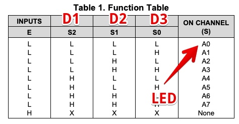
- I made an Arduino code getting S0, S1 and S2 to LOW
void setup() {
  // initialize digital pin LED_BUILTIN as an output.
  pinMode(D0, OUTPUT);
  pinMode(D1, OUTPUT);
  pinMode(D2, OUTPUT);
}

// the loop function runs over and over again forever
void loop() {
  digitalWrite(D0, HIGH);   // turn the LED on (HIGH is the voltage level)
  digitalWrite(D1, HIGH);   // turn the LED on (HIGH is the voltage level)
  digitalWrite(D2, HIGH);   // turn the LED on (HIGH is the voltage level)

}
But the LED was still on!!!
I changed my code to set all the D pins to LOW, I could just have been thinking inverted. But no difference.
I checked my wiring on the board. Using the Pin configuration and Overview. But I found a ‘MISTAKE!!??’ in the Datasheet?
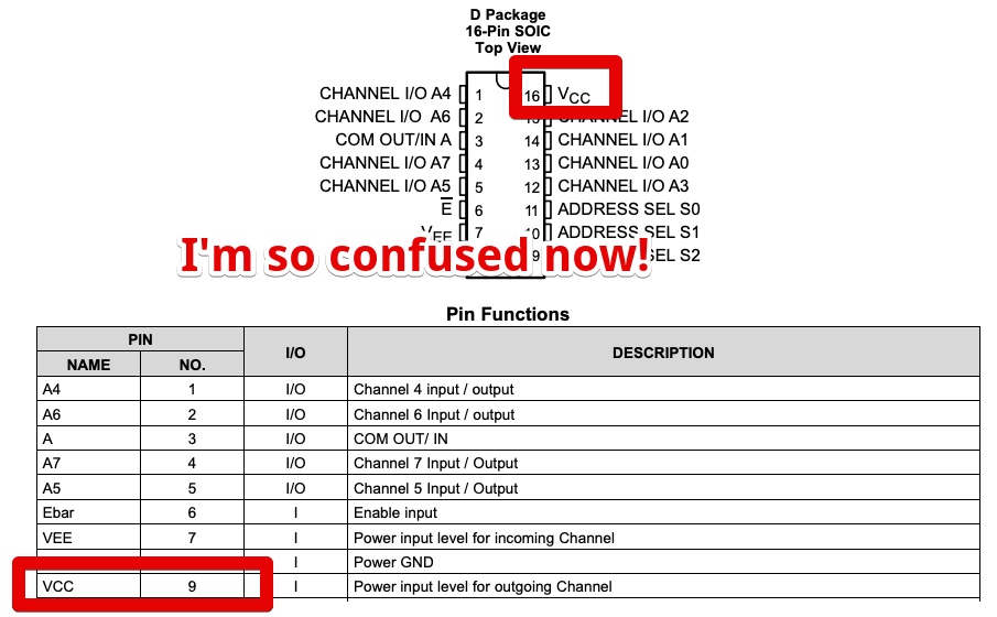 I looked in the datasheet, all the other tables and schematics pin 16 was connected to VCC. Or don’t I just get it?
I decided to ignore this table and checked all voltage levels with a multimeter
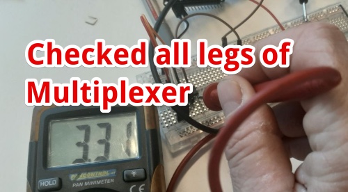 All looked oke. Only the output on A0 leg to LED&resister was 2.8 Volt. This should be 3.3 volt!
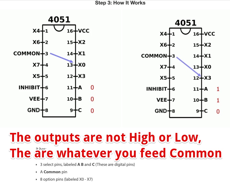
I looked on the internet for schematics how to hook up this component and found this great post on Instructables. Explaining me I had It all wrong. From the table I was sure the output was Low Or High. That what the table shows. ‘L’ or ‘H’. But this is only true for the inputs. The output is connected to the COMMON or Not Connected to COMMON
I connected leg 3 to the 3.3 volt and the led was Off! Then I draw the schematics how I should connect two 6 LED’s (2xRGB)
To get the full test of a multiplexer I should drive more than 3 outputs with 3 legs of the Microcontroller. That is the goal. So I connected two RGB leds (With 8 legs in total) to the multiplexer. And made this test code:
void setup() {
  pinMode(D0, OUTPUT);
  pinMode(D1, OUTPUT);
  pinMode(D2, OUTPUT);
  Serial.begin(9600);
}

void loop() {
  digitalWrite(D0, LOW);   // turn the LED on (HIGH is the voltage level)
  digitalWrite(D1, LOW);   // turn the LED on (HIGH is the voltage level)
  digitalWrite(D2, LOW);   // turn the LED on (HIGH is the voltage level)
  delay(1000);
  Serial.println("Output A0 is ON");

  digitalWrite(D2, LOW);   // turn the LED on (HIGH is the voltage level)
  digitalWrite(D1, LOW);   // turn the LED on (HIGH is the voltage level)
  digitalWrite(D0, HIGH);   // turn the LED on (HIGH is the voltage level)
  Serial.println("Output A1 is ON");
    delay(1000);

  digitalWrite(D2, LOW);   // turn the LED on (HIGH is the voltage level)
  digitalWrite(D1, HIGH);   // turn the LED on (HIGH is the voltage level)
  digitalWrite(D0, LOW);   // turn the LED on (HIGH is the voltage level)
  Serial.println("Output A2 is ON");
    delay(1000);

  digitalWrite(D2, LOW);   // turn the LED on (HIGH is the voltage level)
  digitalWrite(D1, HIGH);   // turn the LED on (HIGH is the voltage level)
  digitalWrite(D0, HIGH);   // turn the LED on (HIGH is the voltage level)
  Serial.println("Output A3 is ON");
    delay(1000);


  digitalWrite(D2, HIGH);   // turn the LED on (HIGH is the voltage level)
  digitalWrite(D1, LOW);   // turn the LED on (HIGH is the voltage level)
  digitalWrite(D0, LOW);   // turn the LED on (HIGH is the voltage level)
  Serial.println("Output A4 is ON");
    delay(1000);


}
Then I draw the schematics how I should connect two 6 LED’s (2xRGB) 
Heroshot
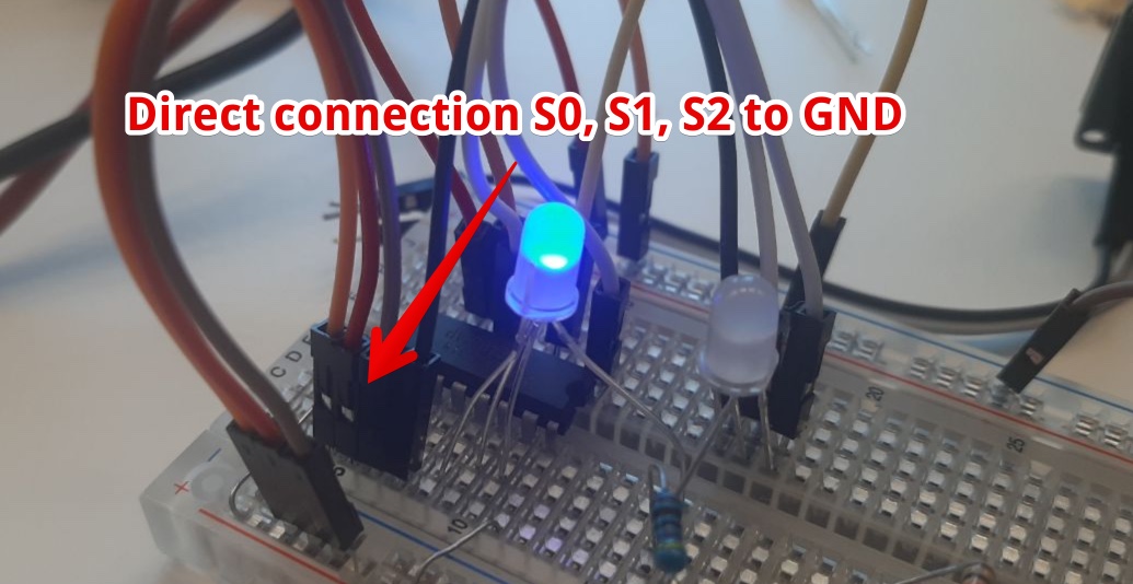
It shows multiplexing is working! I have 4 LEDS (4 colors) burning with just 3 legs attached.
But something is still wrong,
the blue color of the left led is not on.
I changed the code with 4 seconds delay to compare Serial monitor output to the LED states ` delay(4000); `
And noticed state A0 didn’t ‘happen’ this is where the blue of the RGB led was attached. So I directly connected the inputs to the GND. This helped! A0 is High!
- I made the Arduino code more simple, just to find Why A0 LED was not ON when set via the Node. I changed the code to:
void setup() {
  pinMode(D0, OUTPUT);
  pinMode(D1, OUTPUT);
  pinMode(D2, OUTPUT);
  Serial.begin(9600);
}

void loop() {
  digitalWrite(D2, LOW);
  digitalWrite(D1, LOW);
  digitalWrite(D0, LOW);
  delay(4000);

}
This worked, the A0 LED was now high. So problem solved. But why??
- I changed the Arduino code back to address all the LED’s. And all led states now work according to be expected from the datasheet. So I can’t explain. But I noticed the breadboard sometimes was not working perfect. I start to agree with Prof. Gershenfeld: he does not like Breadboards because new components only come as SMD and breadboards have connection problems.
Mistakes/mental notes
- My mental model of the Multiplexer was wrong, so I didn’t get the datasheet (while I thought I was)
- I should first look into the function of an component (via the Internet) and than look into the datasheet
- I don’t need a multiplexer, it only powers ONE output at a time. So I can’t use this for my final project…
- Making more complex schematics with a breadboard can cause loose contacts
Superhero shot
I Finished this assignment in week 6, 9 and 10:
- I designed, made a working board and programmed it to change the blink frequency of a led according to the input sensor in Electronics design Week
- I designed, made and programed a non working ESP-12F board in “Input week”
- I succeeded to make and program a working ESP-12F board during week 10
Final conclusion for this week
Biggest Mistakes and lessons this week
- Make a plan before and don’t assume all goes as planed
- Think in parallel process
- Assumption is the MOFO
Wat I really liked
- It was interesting to find out ESP8266 had a lot of meanings.
- I got better in reading datasheets
- I got the multiplexer working
My concerns
- Programming my final project in 2 weeks is impossible