Create an ESP-12F PCB
I tried a few times during the weeks to create an board with an ESP-12F chip on it. I failed in week 8 and Week 9. But during week 11 I managed to create a working ESP-12F board. This post was the post will show you how.
Eagle files:
Table of Content
- Make a PCB for an ESP-12F
- where to attach everything?
- Hero shot
- Program the ESP using UART
- Get the ESP-12F in programming mode:
- Start the program loaded on the ESP
- Hero time
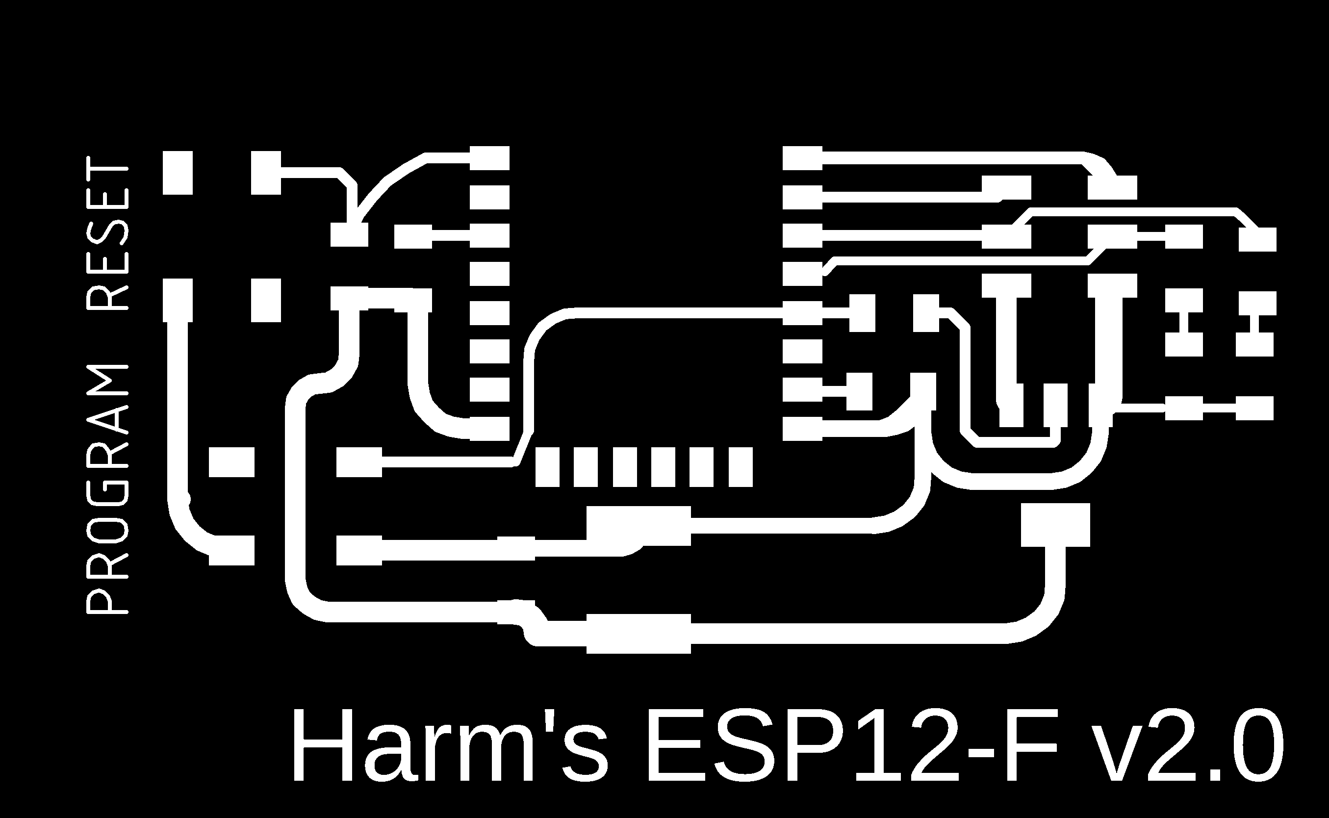
Make a PCB for an ESP-12F
I have been struggling a lot, and was hardly able to get a programm on an ESP-12 module (read all about it in the Embedded ‘[programming week]’)(
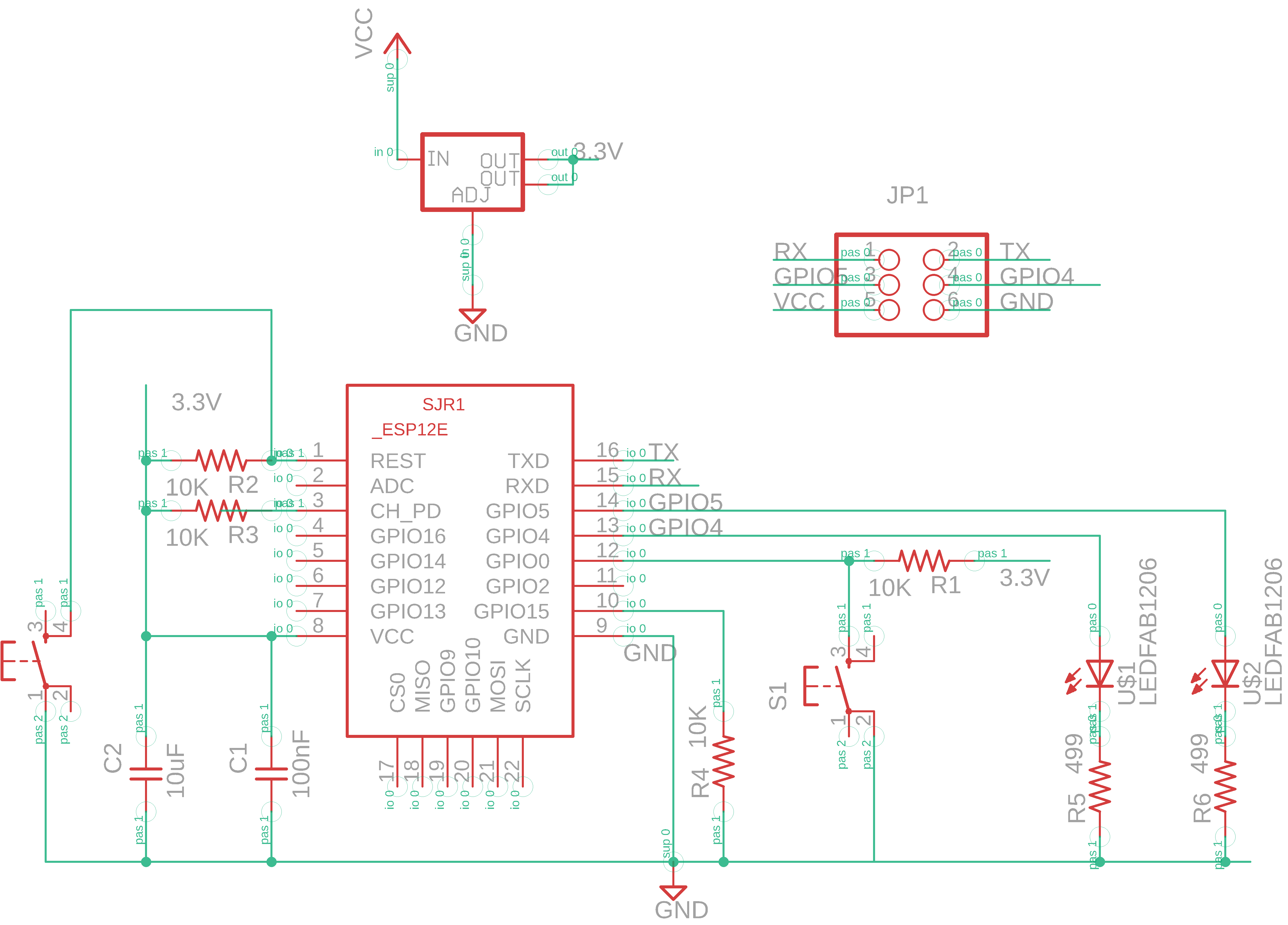
I will use the official Application circuit from the ESP-12F datasheet: 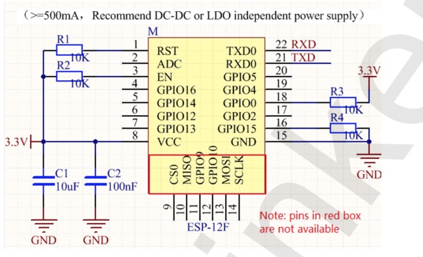
The Datasheet explains how to switch between Running mode (the program is running on the ESP) and the Programming mode (the ESP is able to receive compiled code) 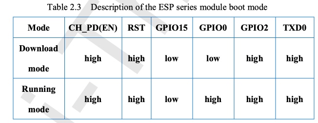
The circuit from the Datasheet does not mention buttons to get the board in programming mode. I found this circuit for buttons via this Youtube video. I used this to create the schematics around the buttons: 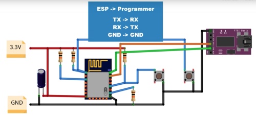
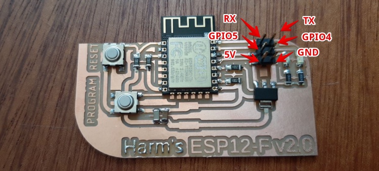
where to attach everything?
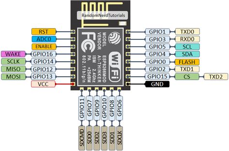
I’m really scared putting any high output on one of the gates of the Mosfets. Even during programming this could burn my material. So I use the two most unused pins to connect the two LED’s. GPIO4 and GPIO5.
Hero shot
Program the ESP using UART
You can How to use any USB to TTL to program a NodeMCU (ESP-12) - UART protocol?

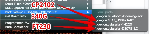
- Using the FTDI:
- Install drivers (mac)
- connect via USB 2.0 hub
- Using the 340G
- Install drivers (mac)
- Using the CP2102
- Install drivers (mac)
If the installation works, plugin the USB to TTL to the computer
Connect the UART to the ESP-12F
| UART | ESP-12F |
|---|---|
| GND | GND |
| TX | RX |
| RX | TX |
- GND of the ESP-12 to GND of power supply
- VCC of ESP-12 to 5V
In the Arduino IDE
- Set Board to ‘Generic ESP6266’
- Set Port to ‘cu-usbserial1414’
- Open an Empty sketch (to test if upload is working)
- Upload
Arduino IDE settings: 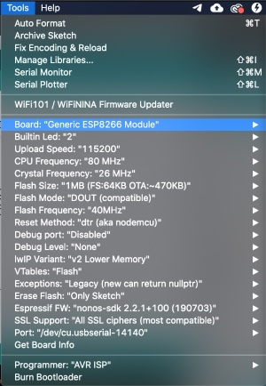
Get the ESP-12F in programming mode:
Just after pressing ‘Upload’ in Arduino. On the ESP-12F board:
- Press & hold RESET (button on REST)
- Press & hold PROGRAM (button on GPIO0)
- Relese RESET
- Release PROGRAM
Now you will see the uploading starts 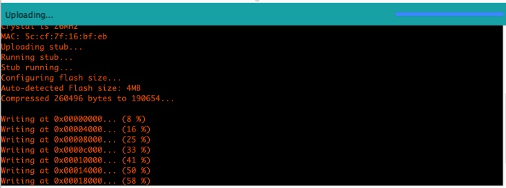
Start the program loaded on the ESP
DON’T forget to press RESET!
- If uploading is ready
- Press RESET, the program will now start running
Now a real test to see of the output of the board is working
void setup() {
  pinMode(4, OUTPUT);
  pinMode(5, OUTPUT);
}

void loop() {
  digitalWrite(4, 0); // set the LED on GPIO 4 OFF
  digitalWrite(5, 1); // set the LED on GPIO 5 ON
  delay (200);

  digitalWrite(4, 1); // set the LED on GPIO 4 ON
  digitalWrite(5, 0); // set the LED on GPIO 5 OFF
  delay (200);

}
Hero time
Mental note:

MOSI MISO = SPI
TX/RX = UART
SLA, SLC = I2C (IIC)