9 - Input Devices
This week we have to measure something with a board we made. I want to use this week to get LDR & temperature input via an ESP-12 module
- individual assignment:
- measure something: add a sensor to a Microcontroller board that you have designed and read it
- group assignment:
- probe an input device’s analog levels and digital signals
How can I use this in my final project?
- Input for my project is:
- Weather data via the WiFi (using an ESP)
- Light in the room, if it is dark no-body will see the painting anyway
The steps for this assignment
- 1. Group: probe an input device’s analog levels and digital signals
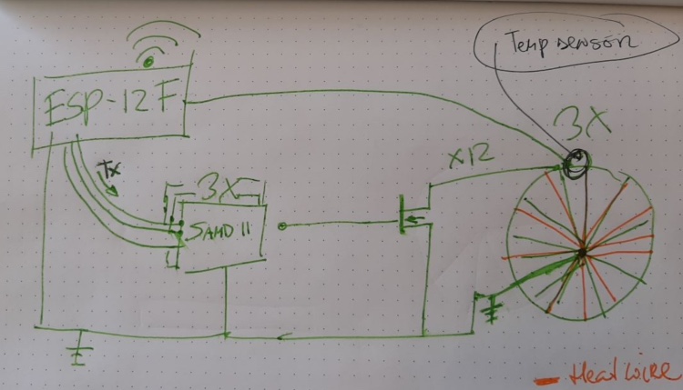
- 2. Create a ESP Module - with input (LDR)/WIFI
- Drawing the ESP-12F module in Eagle
- Draw the schematics in Eagle
- Milling the board
- Uploading code to the board
- Connecting my temperature sensor to a Microcontroller
- Files & Conclusions
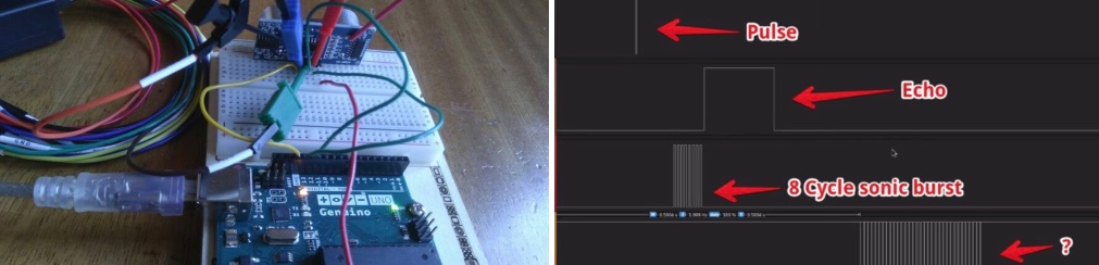
1. Group: probe an input device’s analog levels and digital signals
The idea is to know what the signal from the sensor is and how this is being interpreted along the way.
With the help of Henk we choose the HC-SR05 distance sensor.
Our plan is to see the different input:
- Registered by a microcontroller (and visible in the serial monitor)
- Via an analog measurement device (voltage levels on the sensor)
We installed the sensor in a Corona together remote way. We all had one board (NodeMCU) in common, so we decided to use it for this week’s group assignment. It turned out the signals on the sensors are interpreted by the Arduino code and translated into readable output. read all about this group assignment
2. Create a ESP Module - with input (LDR)/WIFI
- First step is to make sure what kind of ESP i have. My board looks like an ESP-12. But the ESP-12E, ESP-12D, ESP-12F all look very simular.
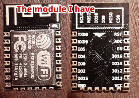
But according to the ESP8266 wiki the Antenna of an ESP-12 F is different from the others. I do have the ‘extra long antenna’ So it must be an ESP-12F.
The datasheet is hard to find, I can only find the datasheet for the ESP-12F from Thinker-AI. According tot the logo on my module it is made by Wroom. I cannot find the difference and the websites explaining me how to hook up an ESP-12F have both AI and Wroom ESP’s, so I just have to go with the ESP-12F Thinker-AI datasheet
How to get the ESP-12E/F into programming mode
Important information from the datasheet: 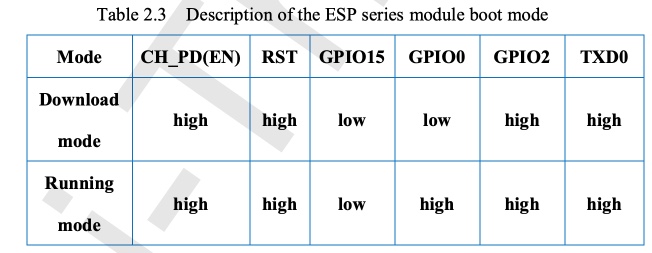
According to this post on Hackster IO we should GPIO 0 low while the ESP module is starting up.
“To get it into programming mode, GPIO 0 needs to be pulled low when the ESP is starting up. The easiest way to do this is to add buttons to GPIO 0 and the RST pin that connect to ground when pressed.
To enable flash mode:
- Hold down the GPIO 0 button
- Press the RST button
- Then let go of both buttons
“You don’t need to perform this sequence at any particular time during the upload process or anything, once the ESP is in programming mode it will stay there till the next reset, so just perform the steps any time before uploading. “
The information above is very important but not in the Datasheet. Or maybe it is hidden in text: 
I Will just reset the module taking the power away, this will save me a button…
Drawing the ESP-12F module in Eagle
- I couldn’t find the ESP-12 module in eagle. It is nog in the Eagle Lib and not in the Fab lib. So I start searching on the internet and found this git Repro with the 12E module, Since only the antenna is different I went with this. ESP-12E library
Add the Library to Eagle: (menu) > Library >
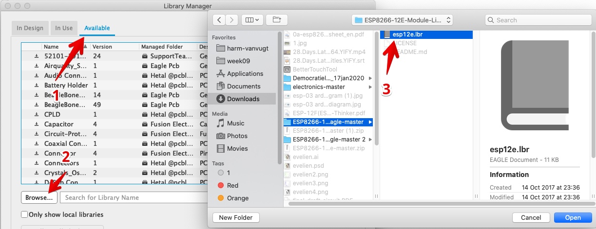
Add the Lib and Click - USE
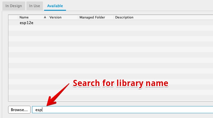
Close the Library manger
- the ESP
- ESP, it is really hard to find the library component for the ESP-12F the footprint of ESP-F should be similar. So I went with the ESP-12E
- The MosFet’s
- I found two FabAcademy MOSFET footprints
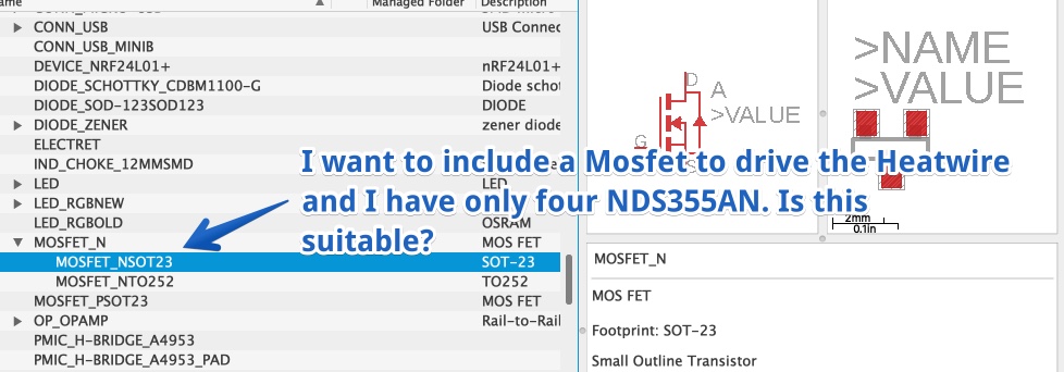 I have 4xNDS355AN SOT-23 mosfets. But will they work?
- I found two FabAcademy MOSFET footprints
- I checked NDS355AN datasheet to see if I can use this component to drive the Heat-wires
- I want to use 5V to drive the Heatwires/Heatpaths
- The heatwire could be 400 mA (I measured 2A for 6 wires with the 47Decrease Thermochromic paint, see Final Project)
- I looked in the datasheet Mosfet NDS355AN datasheet and tried to find the Voltage on the gate vs The current through the Drain and Source.
I couldn’t find what I was looking for and found this answer on Stackexchange:
“Most data sheets (all good ones) contain graphs that show the current that can be passed at various combinations of Vgs and Vds.”
So I searched the datasheet for Vgs (Voltage between Gate and Source causing the amount of Current to flow between Drain and Source) I found
1.7A, 30 V, RDS(ON) = 0.125 W @ VGS = 4.5 V
So this tells me 1.7 Amp can flow when the gate gets 4.5 volts. I plan to drive it from a ESP-12. So standard 3.3 volt
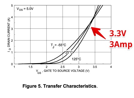
So Yes, It should work with 3.3 Volt!
How to connect a MosFet to a ESP output port?  Oke, now it is time to give Google a change to answer this question: Some schematics show two resistors at the gate, and this post explains is again one from StackExchange
It is generally a good idea to include a gate resistor to avoid ringing. Ringing (parasitic oscillation) is caused by the gate capacitance in series with the connecting wire’s inductance and can cause the transistor to dissipate excessive power…
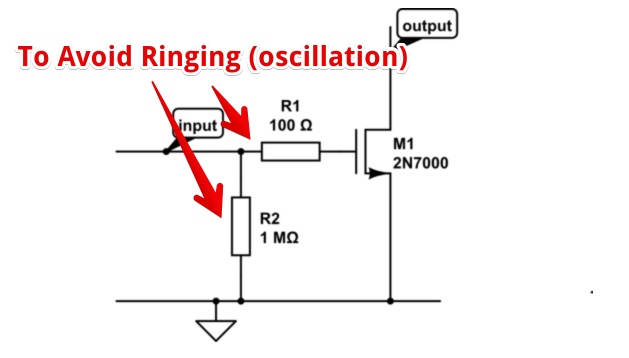
I assume this ‘Ringing’ will happen on a state change. I plan to only change the value on time per forecast, so every 6 hours, And I need 36 MOSFET’s so 2 extra resistors per MOSFET = 72 resistors = 144 legs to solder! I will take my changes and do a test without.
Conclusion: MOSFET direct on the ESP!
Where to connect the MOSFET’s?
I want to use pins that are not needed for programming or other functions. I found this overview on www.commenthow.com
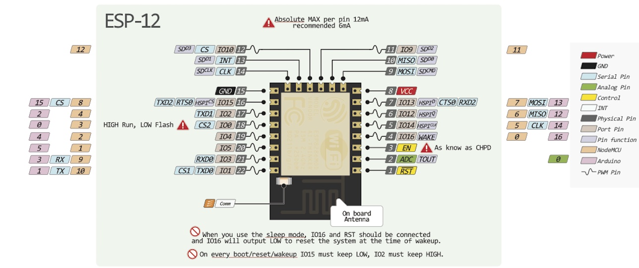
Two pins are not used for anything else
- IO4
- IO5
So I Directly Connected MOSFETS to IO4 & IO5. 
how to make sure the heat-paths/wires don’t overheat?
If I have a big current power supply and open Just one of the 36 MOSFET’s, all the current will flow to this heat-wire/pad… This will get to hot? I HAVE TO CONTROLL THE CURRENT THROUGHT THE HEATWIRES!
Solution: I should only open the gates completely when All heat wires have to be powered. If only one wire is heated, the Drain Source current should be 1/36 of the maximum. So I can’t use a shift register! This only can power the gate ON or OFF. I need a IO extension capable of setting the voltage of the pins (to the Gates).
Nice to test this with two MOSFET’s on a board. But still it is smart to include a temperature sensor. Just one per day, to make sure i don’t set the painting on fire…
How to include a temperature sensor? What temperature sensor should I take? Neal mentioned the NTC & RTD. They both suit my temperature range of 10°C - 60°C
NTC:
Operating Temperature -40°C ~ 125°C
RTD:
Operating Temperature -55°C ~ 155°C
Since I’m not sure if the Waag has these components I looked up how a DHT11 works. This is a temp/humidity module I have at home.
Found the inside on how to Mechatronics 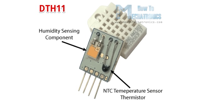
It is a NTC sensor and I should be Able to unsolder this one if the Waag has no supply. Only question remains:
How should I connect the NTC to the ESP?
Neil explained we could use 3 resistors and the thermistor, to prevent wrong reading caused by the resistance in the copper of the PCB. I’m not interested in a very accurate measurement. My biggest problem will be to get the sensor really close to the object (heat wires). It is only to prevent fire. So I go for a single resistor of 10K (I assume the NTC in the DTH11 is 10K) 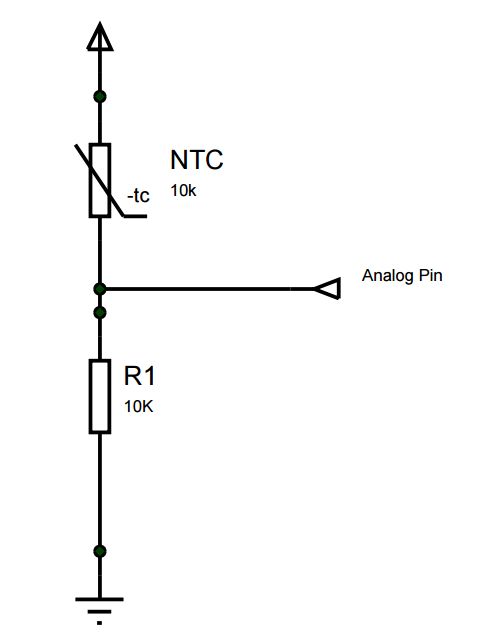
The GPIO layout of the ESP tells me there is only one Analog pin. This is pin 2 (ADC).
How to find the Component in Eagle library?
The eagle Library (fab lib) does not show the NTC, I added the PCT NTC lib  But the SMD footprints are not available.
So I looked up the size of the NTC SMD in the datasheet we could use (as mentioned on the FabAcademy site), and it is the same size as a 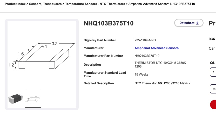
Solution:
I used a normal 1206 resistor
Draw the schematics in Eagle
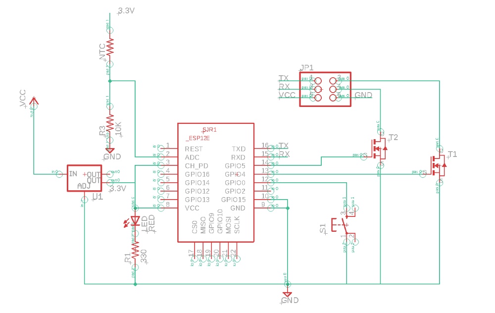
From the schematic I made an PCB by hand (did not use AutoRoute). All traces are made no ‘AirWires’, so I should be happy, but…
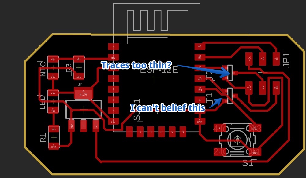
Problem
I Did not like the thin copper wires on my board, they turned out to be 16mil. And according to my design rules it was possible to create a copper line in between the legs of the MosFet. These components are extremely small, a copper trace should never go under it.
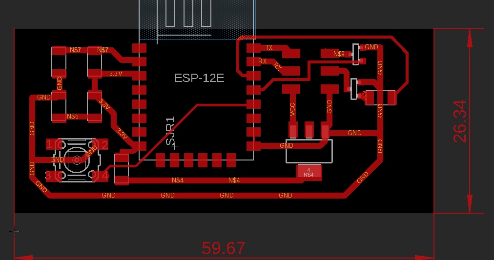
Start Over
So I started over again and came up with this PCB. I had to ADD two 0ohm resistors. But the traces are really thick
I wanted to see this in 3D and used these steps:
To view the 3D model
- in PCB view > Click on ‘FUSION 360 TAB’
- Push to Fusion
- View on the Web
This error message emerged 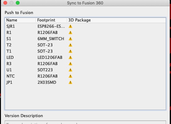
The 3D packages ar not in the standard Fab library, but it is still interesting to see the 3d version
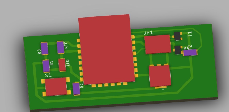
I’m happy with the traces, Thick traces for ground, VCC and from the Mosfets. The thin traces are the gate for the Mosfets and the Pulldown with the button, for getting the Board in Flash mode.
Milling the board
Henk did the milling from the waag. But het discovered a mistake when loading the Outline file in the MODS:
- Only one line was visible in the original outline file…

It turn out Eagle does not export thin lines in a rectangle…
I changed the line thickness 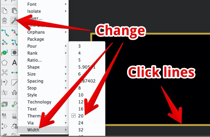
And I exported again: 
But Now the offset of the cutout was wrong. I looked into the file but the only thing I changed are:
- Adding dimensions
- I moved the dimensions to the top, and now no offset from bottom (starting Y was visible)
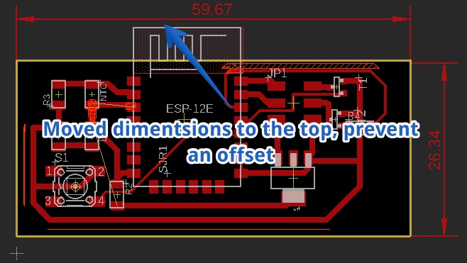
This is the proper outline 
Uploading code to the board
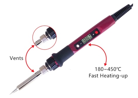
Alhough we have no acces to the Maker Lab due the Corona, I soldered the board with relative easy. My cheap soldering iron from Aliexpress was oke
My Magnifier glasses looked amazing. At the end I was on my knees to not completely have to bend over all the time. My had really has to be close to the object to get it focused. 
When I connected the board via the USB to UART Arduino Recognized the Connection. But refused to upload. 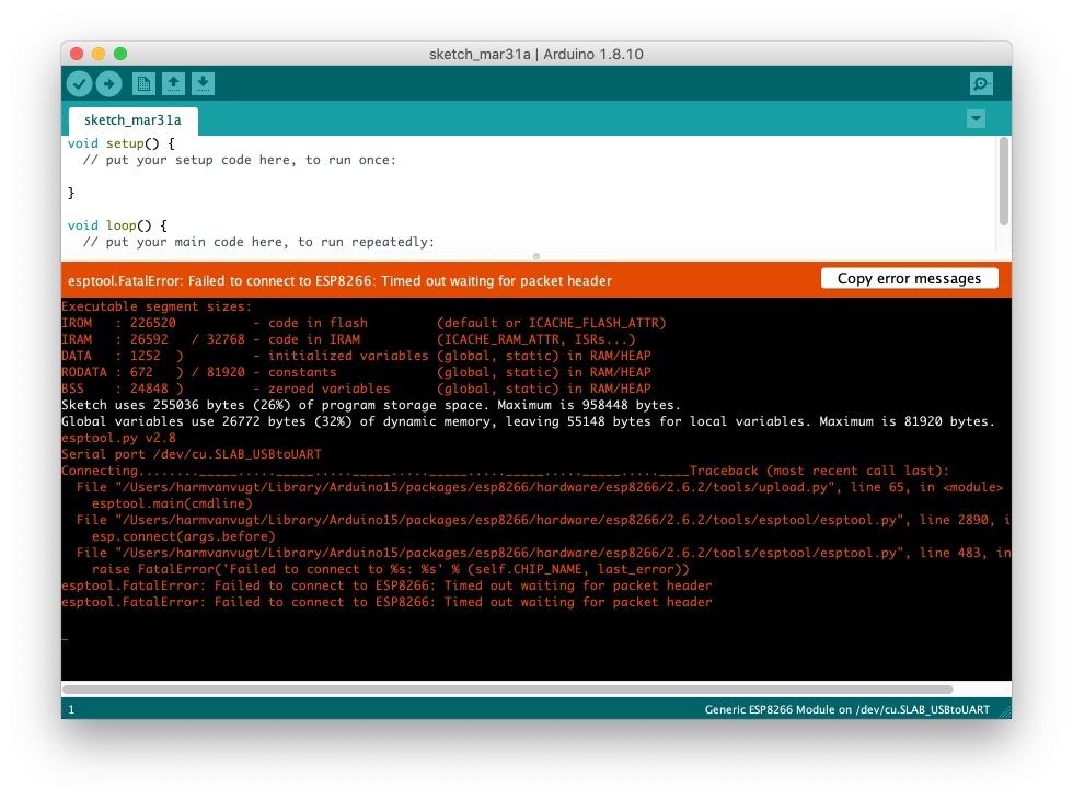
Of course I tried all ‘set into Flash’ options available
The LED on the ESP-12 module was blinking fast, so RX & TX connection was connected well.
Possible problems to look into
If my week was not finished again…
- Did I use the right way to connect the GPIO’s?
- I checked all, no mistakes. but a lot of discussion
- Most posts say you need resistors to connect the GPIO’s
- On the Fab page of Luc Hanneuse he does not use any resistors, but he never got the board to work
- What should be the settings of my Arduino IDE (board settings)?
- Nodemcu 1.0 (12E)
- ESP8266
- Should I set the flash size?
Do I use the right sequence to get the ESP into boot mode? I just SET the device in boot mode while starting up. I assume it stays in this mode till next time you take the power off. But is ‘reset’ the same as taking the power off? (some posts say so…)
- Can I do it with a 5 UART?
- I’m using a 5v UART, according to the specs the RX and TX of the ESP-12Eare 3.3 volt max.
- Like i mentioned in this page before, lots of people mention It ‘should’ work with 5v TX/RX A hack a day spend a entire post to this question this post “Is ESP8266 I/O really 5V tolerant?” answers with a sort of YES. But other post warn you not to use more than 3.3 volt, the datasheets mentions a max of 3.6 volts.
I give up! I have to get input in a board and display data!! Next week again a ESP-12E attempt.. Next time I will -
- Read the ESP-12F datasheet again and now fully rely on it
- Use an 3.3 v UART…
I used this he simple schematics from Domotix, looking at the datasheets again it can’t be right…
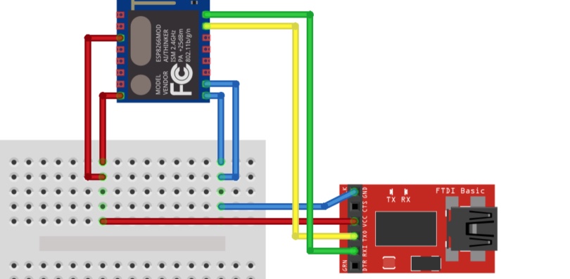
Now I trust this schematics more I want to reverence these connections with datasheet 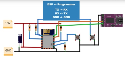
This is the official Application circuit from the ESP-12F datasheet , I will follow this next week 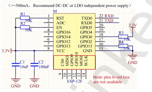
Connecting my temperature sensor to a Microcontroller
I still wanted to connect the sensor on the PCB I made to a Microcontroller, but the NTC thermistor is on the PCB…
How can I measure with the sensor while on the (not functional) ESP-12 board?
- I soldered wires on both sides of the NTC
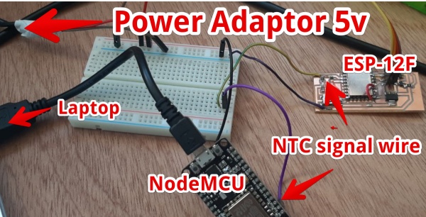
- connected the signal wire to the A0 of a node MCU (with an ESP-12E on it)
- Connected the Ground signals together
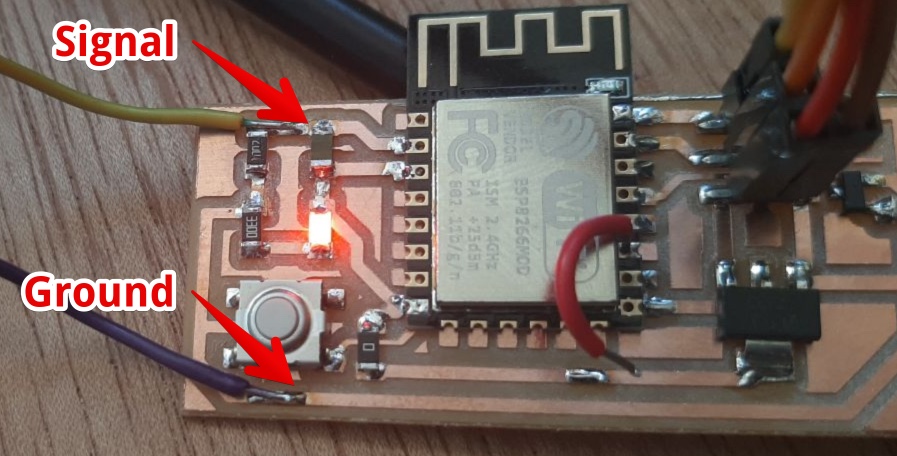
- Used a 5v adapter to power the PCB with the NTC and resistor.
- Connected the ground of the NodeMCU to the ground of the ESP
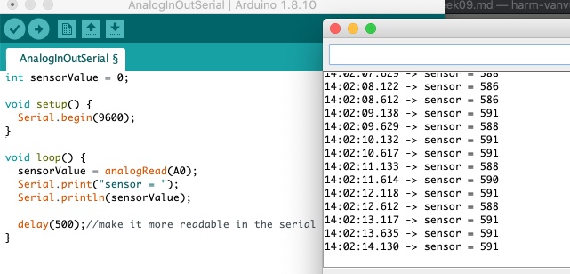
Opened the example code from Arduino IDE > Examples > Analog > AnalogInOutSerial.
Changed the example code to this:
int sensorValue = 0;
void setup() {
Serial.begin(9600);
}
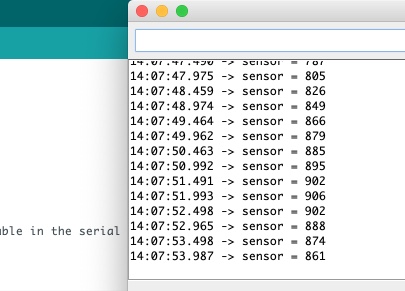
void loop() {
sensorValue = analogRead(A0);
Serial.print("sensor = ");
Serial.println(sensorValue);
delay(500);//make it more readable in the serial monitor
}
Uploaded the code.
The sensor Output was about 591 (I think it was 20°C in the room at that moment)
I set my soldering iron to the lowest 180°C Checked the NTC datasheet:
- the max operating temperature is 125°C, So lets see if I can push it!
I added a multimeter to measure volt. It is set on the millivolt range. When I put the soldering tip on the NTC (without making a short circuit) it goes to 2 volt. I don’t dare to keep the solering iron on for more than a few seconds
So I assume:
| temp | Read Voltage | Read Serial Monitor |
|---|---|---|
| about 20°C | 1,76 Volt | 590 |
| about 140°C | 2,3 | 1000 |
I looked in the datasheets to find the resistance/temperature specs. And i found ` Maximum solder temperature: 509°F (265°C)`
So I really hold my 180°C soldering iron to one of the sides for 20 seconds. The readout was
- 3,13 VOlt
- 1023 in the serial monitor
Since the voltage did not rise the last few seconds I assume the max temperature of the NTC was reached.
There is a way to calculate the temperature when you know the voltage the website of Jameco it all
But there is no “look-up table containing temperature-resistance data for your thermistor” in the datasheet.
the curve for an NTC is pretty straight, found this on Jemeco’s site 
According to the reference of Arduino about analogRead() you could calculate it. I will for my final project!
Files & Conclusions
I made and programmed a working input board in week 6 using an Photo-transistor. This week I spend a lot of time on a ESP-12F board with a NTC on it. The ESP-12F board is not fully functional, but I succeeded to read this NTC by using an other board.
In week 12 I read the NTC input and displayed this via Processing.
Files this week
Biggest Mistakes and lessons this week
- I thought I had my Eagle Design Rules figured out, but again firs PCB failed
- When it comes to programming an ESP-12 module, I relied to much on internet post for information, I need to look at the Datasheet as a main source!
- I totally underestimated how much time it will cost to program an ESP-12
Wat I really liked
- I managed to find enough data about the components to make a custom board
- I really could think about my final project
My concerns
- How can I make sure the heating does not set my paining on fire?
- This is the second week I tried to use an ESP-12F module, again no success and not too much progress, should I give up this module and use a NodeMCU?