12 - User interface
Write an application that interfaces a user with an input &/or output device that I made. The goal is to make an interface running on a computer (not a microcontroller). Use a PC or smartphone.
Assignments
- Individual assignment: write an application that interfaces a user with an input &/or output device that you made
- Group assignment: compare as many tool options as possible
How can I use this in my final project?
- I would like to see temperatures from my boards
Page Index
- Group Assignment
- What User input (via a computer) would I like to use in my painting?
- What would I like to display on a computer?
- Can I display the temperature in time
- Final Code & Conclusion
Group Assignment
Since the Covid-19 restrictions are still in place, we in a video conference.
- group: compare as many tool options as possible
- Harm: Block based coding tools. My conclusion, it is not usable with Non Arduino hardware.
Read all about our group assignment
What User input (via a computer) would I like to use in my painting?
It would be nice to completely change the colors of the tomatoes when I want. So I need to send a command from my laptop (later a smart phone) and make the tomatoes red.
Neil recommends using Processing, when you know a bit of Arduino. I will go for this since I had a really frustrating time getting ‘Block based coding’ to work (see group assignment).
Installing Processing is easy. Just download it from their website and install, I moved the application to the ‘Applications folder’, but It runs from every directory. 
I noticed the menu structure of the UI is similar to Arduino.
Browsing trough the examples (File > Examples) I found several serial port examples. This could work with ‘Arduino’ Serial communication. I opened the Serial write. Because for getting input form my laptop to the microcontroller I want to write to the microcontroller.
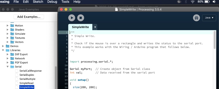
This example even came with some Arduino Example code:
  // Wiring/Arduino code:
 // Read data from the serial and turn ON or OFF a light depending on the value

 char val; // Data received from the serial port
 int ledPin = 4; // Set the pin to digital I/O 4

 void setup() {
 	pinMode(ledPin, OUTPUT); // Set pin as OUTPUT
 	Serial.begin(9600); // Start serial communication at 9600 bps
 }

 void loop() {
 	while (Serial.available()) { // If data is available to read,
 	val = Serial.read(); // read it and store it in val
 }

 if (val == 'H') { // If H was received
 	digitalWrite(ledPin, HIGH); // turn the LED on
 } else {
 	digitalWrite(ledPin, LOW); // Otherwise turn it OFF
 }
 	delay(100); // Wait 100 milliseconds for next reading
 }
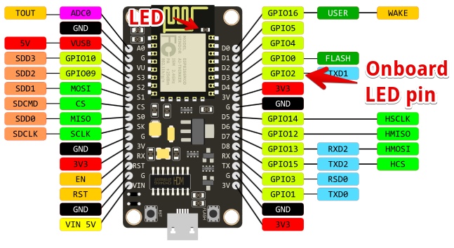
I had to change int ledPin = 4; to 2. Since I use a NodeMCU v3 with the on board LED connected to GPIO pin 2
The processing app reacted on my mouse, on mouseover It turned gray. But the led did not change.
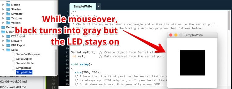
Since the on-board led of the NodeMCU is on the TX pin, this could disturb communication?
I changed the output of the NodeMCU to another pin and attached an external LED with. But Still it did not go on.
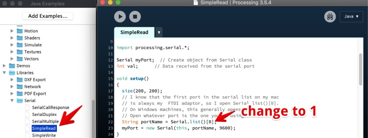
I looked through the Processing code and found this:
  // I know that the first port in the serial list on my mac
  // is always my  FTDI adaptor, so I open Serial.list()[0].
  // On Windows machines, this generally opens COM1.
  // Open whatever port is the one you're using.
  String portName = Serial.list()[0];
I looked in my Adruino IDE (Tools > Port) and found my UART is the second on the list. 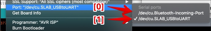
So I changed
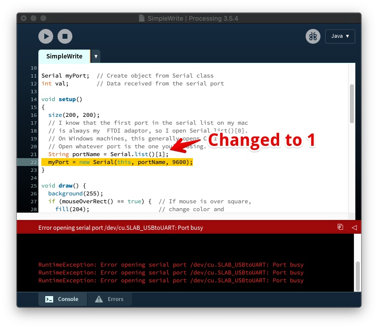
String portName = Serial.list()[0];toString portName = Serial.list()[1];.
Again Ran the code (Press PLAY in the Processing IDE) and it came back with a beautiful warning:
“RuntimeException: Error opening serial port /dev/cu.SLAB_USBtoUART: Port busy”
I tried to find what keeps my Port busy, so I did some tests:
- I unplugged my NodeMCU and the code ran without errors. I plugged in the NodeMCU and It works!(LED on and off with mousover)
- I closed Arduino and started the Processing code again.
- I opened the Arduino code again, and it still worked!?
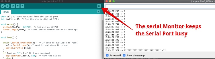
- I opened the serial monitor (is closes when you restart the Arduino IDE) and I got the error message again in Processing
Hero time: When I go (mouse)over the black square, the LED goes off, when I go outside the box, the LED goes on.
Since the LED goes on when the mouse is out the box, I tried to change the Arduino code and upload again. I got an error message: 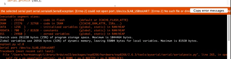
I fixed this by closing the running processing code, the the upload worked.
Conclusion: You can’t keep the serial monitor from Arduino Serial monitor to PC open when it is needed for communication between Processing and the Arduino board. And the other way around.
Can I control a Microcontroller wireless via my smart-phone?
I want to controlling the heatwires in my final project via a website/application, and it has to be wireless. I’m not going to plug in a USB cable to my painting and connect it to my laptop. To get this done I should wait for the ‘Fab Networking week’.
So this experiment worked, I could push it (make a nice UI, control multiple outputs), but there is no use for my final project.
What would I like to display on a computer?
Nothing really, the whole idea is to not use a screen, they are forbidden at our kitchen table. But I would like to have display data in my Final project:
- Weather data (but there are perfect wind applications I use now)
- Temperature data from my heatpaths
- I don’t see how I can do this for every wire, but including one NTC on every heatpath could be smart.
Display sensor data from a microcontroller on my laptop
In Processing I found an example to read data from a device connected to the serial monitor. I changed the port again to the second port in the list = [1]
In the Arduino code I only changed the switchPin = 2 to 4. The Arduino code is inside the Processing code.
I attached a Jumper to GPIO 2 and connected it to GND or 3V. (Since the Covid-19 restrictions I have no acces to a switch). And I could see the color of the square in my computer change. So it works.
Can I display temperature data (From a microcontroller) on a laptop using Processing
The temperature data from the NTC board is analog. So I tested the analog input first by changing the Arduino code to:
int val; //create a varable named val

void setup() {
  Serial.begin(9600);                    // Start serial communication at 9600 bps
}

void loop() {
  val = analogRead(A0);//get data from the analog pin
  Serial.write(val/5);       // Write the data to the serial communication port
  //Serial.println(val); // show the val data in the serial monitor. DONT USE serial write and serial Print AT THE SAME TIME

  delay(100); // Wait 100 milliseconds
}
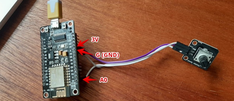
I connected a variable resistor to the NodeMCU
Changed the Processing Draw function code to:
void draw()
{
  if ( myPort.available() > 0) {  // If data is available,
    val = myPort.read();         // read it and store it in val
  }
  background(255);             // Set background to white
  fill(val);                   // set fill to
  rect(50, 50, 100, 100);
}
I had to play around with the number (#)to device val by Serial.write(val/#). But 5 worked fine:
Hero shot:
How to display the temperature in time using processing?
It would be nice to keep track of the temperature in my final project. Or at least in the testing phase, to prevent any further burned materials. So next up: Processing and data in time (graphs?)
Creating a line in Processing: This how to draw a line in Processing helped me to get a line I where I could adjust the height with the analog input.
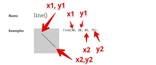
But I need to draw a line every 50 (?) milliseconds, from the old endpoint of the line to the new one. And I have to move all old lines to the left.
I found an example Processing code displaying a value in time, I combined it with the working code (above) to this:
int val;
float prevY;

void setup()
{
 size(600, 600);
  String portName = Serial.list()[1];
  myPort = new Serial(this, portName, 9600);
}

void draw()
{
  if ( myPort.available() > 0) {  // If data is available,
  val = myPort.read();         // read it and store it in val
  }

  line(frameCount-1, prevY, frameCount, val );
  prevY = val;        //top limite of the graph
}
It works, but the x axes should be running/moving to the right. Or it should just wipe all the data when the x value is at the end of the canvas.
I found this video example, it is not sharing or explaining any code, but It sets the x position to zero on the right of the canvas.
In order to do this I created variables for width and height. But Processing does not like this: 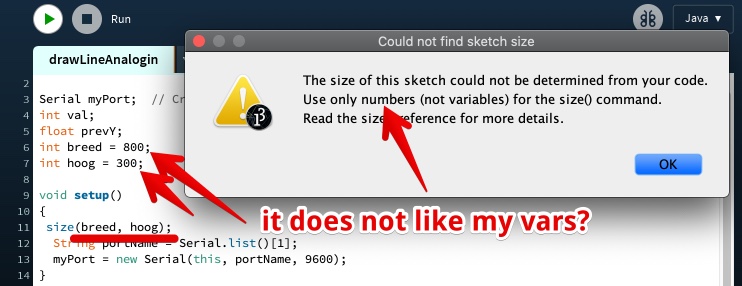
It turn out you cannot use variables to define the with and height of the “display window”. Is this logical? Since you can’t change it (or can you?) after it starts.
Adding this line
if ( frameCount > 800 ) frameCount=5;
and the drawing started at the left, but did not take the old drawing away: 
How to get rid of the old line? this post: ‘draw then delete after a number of steps’ suggested to use background() to wipe all. It gave an error. In the Processing reference I looked up what background needs and it needs a number (color). I made it white.
I added it to the if statement:
  if ( frameCount > 800 ) {
    frameCount=5;
    background(255);
  }
Hero time: My graph works!
Plot graph files:
Can I display the temperature in time
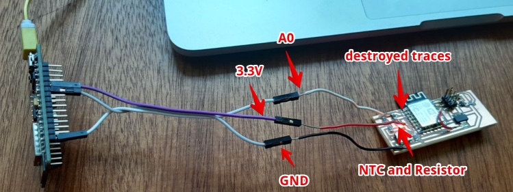
I have no access to an NTC while the lock-down is still in place (till 11 may I hope). So I recycled my not working ESP-12F NCT board. I killed all traces to the other components and soldered GND, 3.3v and output wires on the PCB.
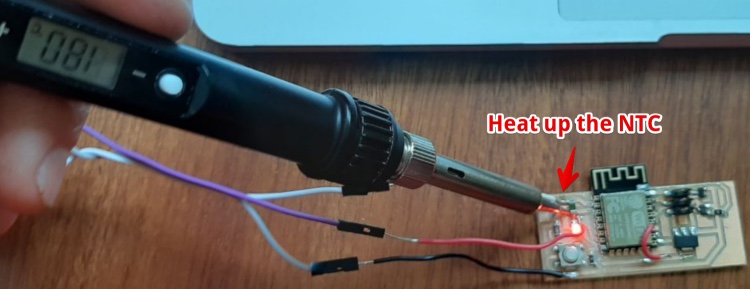
I used an soldering-iron to get nice temperature differences. With the Soldering iron on 180°C it will not melt the solder or destroy the components.
I changed the Arduino code a bit to get a better reading. With the variable potentiometer I divided the ‘val’ by 5. Now I removed this. I Get a nice graph.
But two problems:
- Problem 1. It is upside down (more heat is a lower graph)
Problem 2. It ‘spikes’ when the Y is really high or really low
- Solution 1.
- I changed the ‘val’ variable to ‘-val’ but now the line stays at 0. No success.
- I changed the voltage (GND from node to 3.3 v on the NTC board), this worked
Problem 2, spikes in Y value
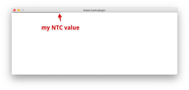
I think my NTC value is just outside of the range of my Processing “display window”. I need to know the value of ‘val’…
How can I display value (text) in Processing?
I would like to read the value of the NCT and display the actual number in my Display Window of processing. the Processing reference tells me I could use this:
String s = "The quick brown fox jumps over the lazy dog.";
fill(50);
text(s, 10, 10, 70, 80);  // Text wraps within text box
So I added this within the draw():
  String s = val;
  fill(0);
  text(s, 10, 10, 80, 20);  // Text wraps within text box
And Processing gave me a error, while typing! This is cool about processing, in contradiction to Arduino, you get error messages while typing. So you don’t have to compile and upload your code to find out you forgot a comma of some other stupid syntax detail.
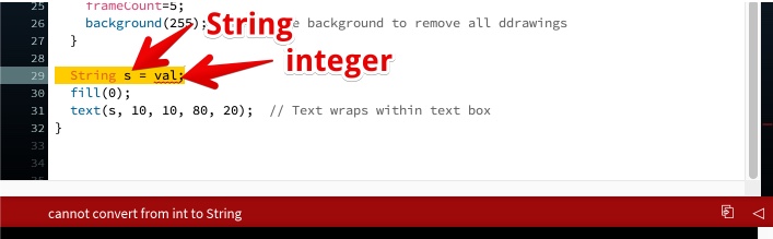
To convert integers to strings has always been a mystery to me. If I have time left…
Processing reverence tells my I can convert numbers to strings by this code:
int i = 1024;
String si = str(i); //Now si holds 1024 as a string
I changed
  String s = val;
  to String s = str(val);
This works! 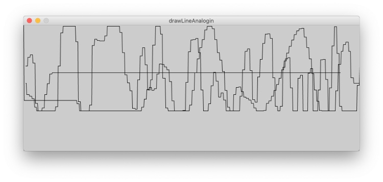
nctESP
But now It overwrites the text field every time, it should remove the old ‘write’ before placing a new one. I Added a counter to place the value every 30 counts (30 pixels?)
if (countTXT == 30) { //every 30 counts put a number down the line
  String s = str(val);
  fill(0);
  text(s, countX+5, 80);  // Text wraps within text box
  countTXT = 0;
}
Now the graph is visible: 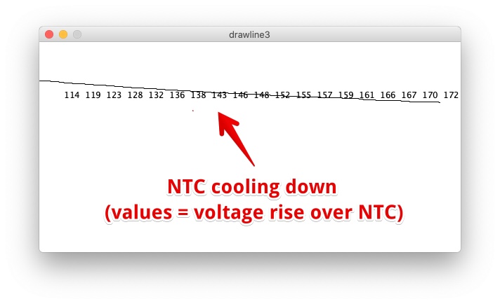
But the value jumps to another ‘range’ when it hits 250.
While the output from arduino is stable. In this video the NTC is about 20C till I put my solder iron (180°C) on it:
When I do the same and show ‘val’ via processing. It looks like ‘val’ jumps to 0 when it hits the 250:
In the left corner you see the result of ` println(val);` so there is nothing wrong with my code.
According to the fill reverence this range is the range for a color, , but I’m not using a color to print ‘val’.
Further steps I took to find whyval will only output 0-255:
- I attached the variable resistor again (potentiometer) to have more control over the input. When I slowly turn it, the processing Console shows shows clearly the value jumps from 255 to 0 and the other way around. So this value cant Only be between 0 and 255.
- Looked float up in the Processing reverence but the max is 2147483647 and as min. = -2147483648
- Changed
intintofloat, but no difference (only float will ad a . and a decimal) - Changed the variable
valin the Arduino code and the Processing code (tostopBeingLimited) - Changed the size of the Processing to 800x800
size(800, 800); - Created an Issue in the global Issue tracker
Nothing seems to help!
I will just limit the output from the Arduino code to 0 and 255. I used the map function: ` stopBeingLimited = map(sensor,482,890 ,19,180);`
I added:
- the line will go red when temperature is above 99°C
- Put the temp value next to the line
- Changed the delay in Arduino code to write every 0.02 seconds
delay(20), to make the graph more fluid
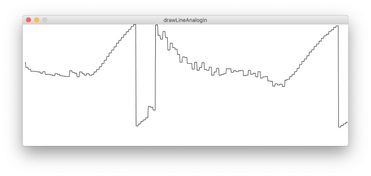
Video below shows the temperature (value of the NTC) when it is at room temperature until I put my 180°C soldering Iron against the NTC. And take it away again (cool-down).
You a the line going a bit ‘wobbly’ it is me struggling to get the SMD tip of the soldering iron on the right spot. A bit of more or less pressure makes a big difference when it comes to heat transfer.
Just before this weeks deadline I got an answer via the Fab Academy 2020 Class Issue tracker why my input is limited to 255:
Processing can only read 1 byte at a time when using myPort.read() 1 Byte holds 8 bits, the max number of 1 Byte is 255 read all about it
Solved!!!
Final Code & Conclusion
Did I make it?
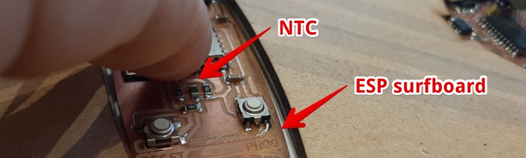
Yes: In week 6 I made and programmed an working Microcontroller board with photo-resistor & button. So I decided to not make an extra board this week. In the final week I made an working ESP-12E ‘Surf’board with NTC.
I used this code with my own ESP-SurfBoard and the code above. I had to change:
- the Mapping since the ESP-12F A0 range is from 0 to 0 volt (where NodeMCU uses 0 to 3.3V) changed to:
stopBeingLimited = map(sensor,396,460 ,29,37);
- the output port in changed to:
String portName = Serial.list()[3];
This is the Interface output from the board in Processing. It was a very hot day, but the 38 should be max 37 (from my finger). So I could change the mapping a bit to get more accuracy. 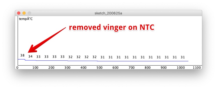
Final Hero code
- Draw a temperature graph with Processing
Biggest Mistakes and lessons this week
- I really wasted two day’s trying to get outdated software running (group assignment), lesson: make sure the software is recently updated!
Wat I really liked
- Playing around with Processing and Arduino
My concerns
- I should dive into software I can really use for my final project, like Node JS or Json (to store data from the internet)