19. Final Project - How to make it
This page describes how I made the final project. I not only used the skills I acquired during the amazing past 6 months but hope a lot of experiments will come to an conclusion and a result to be proud of. This will be a lengthy page… So If you just want to see what I made, just follow the link above “The final Result”.
The steps for this assignment
- Thermochromic paint
- The casing
- Making the passepartout
- Making the backboard
- Make (the painting) a copy of the print
- Microcontroller board (ESP-12F)
- Fitting all the parts together
- Make the I²C heatwire board
- Testing the complete project. heatwires in the frame
- Transferring the heat (using a additive technique)
- What kind of power supply do I need?
- Bill of material
- Hero Time: My final project
Thermochromic paint
During the weeks I continuous tested different Thermochromatic Inks/dye. I made a separate page about the search for Thermochromatic paints. I wanted to turn the tomatoes from green to red. As a positive thing, wind = positive. The idea is to leave my family behind when I go kite-surfing, but then they still have a nice painting with ripe tomatoes. But when mixing the red and green dye it was more black than green (of course!). So I changed the concept to changing the paint from black to red. Red is ‘good winds’.
The paint I used for the final project is the Thermochromic screen printing ink 31°C, from SFXC
How to create a painting with thermoCromatic paint?
I have screen ink and tried to apply this with a brush. But it should be applied by a screen printing. For this I need a lot of materials we don’t have in the lab. The most important thing is the screen (sieve) and a way to cover a part of the screen (by wax or something).
Can I make an (covered) screen using a Laser cutter?
To this screen selling website of Wstyler shows the sizes of screen holes in ‘Mesh’, this is the number of holes per square Inch.
It is from 500 to 66. With a Mesh of 66 the wholes will be 280uM (=0.28mm) the wire will be 100uM (0.1mm). thickness = 200uM (0.2mm). But the smallest screen they sell is Mesh 500. I aim at a medium mesh to test with: Mesh 200 = 0.075 mm.
But is this possible with our laser cutter? In week 3 we found the Kerf of our laser cutter. Them minimum kerf was 0.137 mm (speed 30 power 50). But this was with 2.8 mm cardboard. The kerf should be smaller with thinner material. So I’m trying to make holes of 0.075mm.
How can I make millions of litte holes (a sieve)?
I looked on the internet for ways to make screen printing using a laser cutter. And of course, it had been done: https://www.instructables.com/id/From-artwork-to-completed-silkscreen-in-15-minutes/
But it did not explain to make the little holes.
I used this guide to transfer my image to ‘Dot Matrix the Image’ https://www.instructables.com/id/Photo-Screen-Printing-without-Emulsion-laser-etch/ Steps in photoshop:
- Convert image to grayscale
- Filter > Pixelate > Color Halftone
- Zoom in (cmd-z)
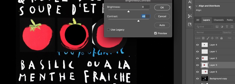
- meshImage > Adjustments > Brightness contrast
This is one of the first test: 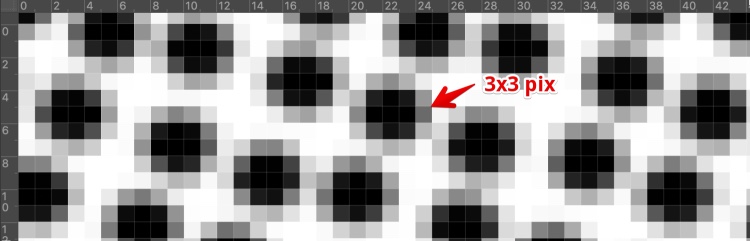
this was the result when wiping screen ink over it: 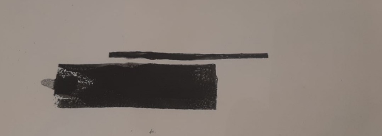
The resolution was 100DPI. A hole (black dot) ~ 3dots = 3dots/1000DPI = 0.003 inch per dot = 0.07 mm This is a medium size Mesh. But the laser cutter kerf width = 0.32 mm so I have to experiment what will happen with different power.
Since I don’t like to calculate in Inches I changed the settings in Photoshop to CM and mm. The Idea is to get
To make calculations easyer i set my photohop to pix/cm When making a file i need to set the 200pix mm = 1 pix = 0.02. So I need holes of 3,5 pixels diameter. Since half pixels are not an option I go for 3 or 4 pixels to get holes of 0.075 mm. 200 pix/mm = 2000 pix/CM
Set photoshop: 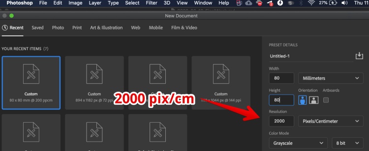
Create the image and Apply the filter: 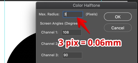
Adjust brightness and contrast to see pixels
I could not find a setting where enough ink would go trough or just made a hole of it. So I made the holes (pix) 2x bigger. So I changed the resolution to 1000 pix/cm 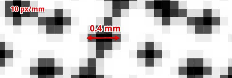
Now I did some tests (noted with double size or 2x in sheet below) 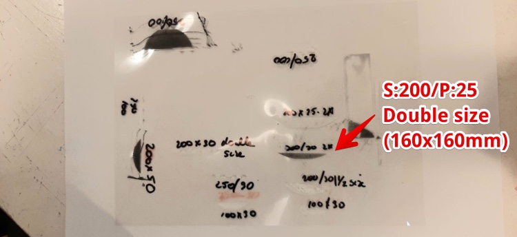
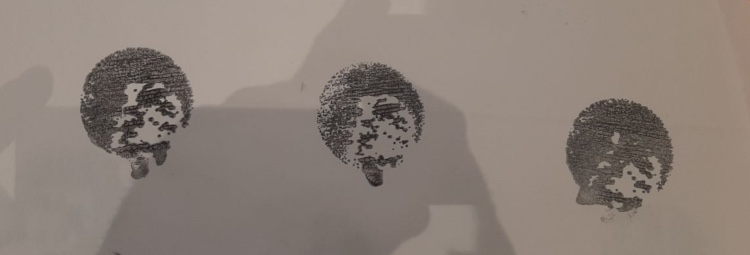
And found the right settings so the material was not cut but still the laser went trough. I made an real screen ink test but it was really dissapointing. One day extra testing and only a step backward. Not enough ink is getting trough and it leaves a smear of ink.
So I went back to the ink supplier (SFXC) and looked for the properties of the ink and found the Thermochromatic ink datasheet (I should have done this before, I know…) it states:
Recommended Mesh Size 90T 70T Minimum Mesh Size 150T 150T
The T stands for Threads per centimeter (UK size), this is 225 Mesh (US) and is 0.06 mm according to this calculator.
Foil is for laser printers, made of PPC = POLYPROPYLENE CARBONATE
I found Mylar is the best material to create a screen for screen printing and ordered this. Mylar is PET (Polyethylene terephthalate). So I ordered this and I hope to find time to test with it.
I could not find the time to experiment with screen printing made on the laser cutter. So I used a paint brush to apply the ink.
The casing
Glue only will not do. The frame should house the painting, the glass and the passepartout. It will be the casing for the heatpaths, microcontrollers, wires and power supplies.
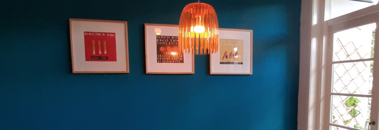
This is the artist impression I made in week 1. Now I changed to displaying wind in a painting with tomatoes. But the idea is still based on this design:
3D drawing - Designing the frame
I designed the frame in 3D in week 3 but I had to redraw it with the design rules of the CNC machine:
- I can’t just cut it out, it will be loose and the spindle will kill it
- I have to consider the outer corners (will be round from the Mill)
- I need to consider time: a just cut it out from a massive piece of wood could take days
- I have to consider the Mill I’m using
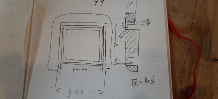
At the end I created the entire piece of material the frame will be made out in 3D: 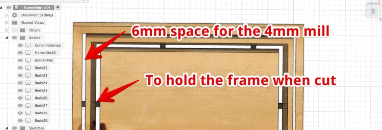
CNC machine - Create the actual frame
I should redraw the wooden part of the frame and make a press-fit. I could CNC it from multiplex. But than I should remake all three frames in my kitchen. But since it is spiral design, lets start with one first.
I want to use real wood and not multiplex and I really would like to use material we already have at the FabLab. I found and old table top of 2.7 mm thick.
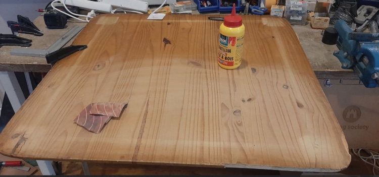
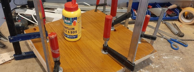
Not thick enough for my frame. So I cut it in two and glued it together. When cutting a noticed the wood is really not strong
So I decided to glue them and use the fiber in a 90 decrease direction, so I created my own multi-ply
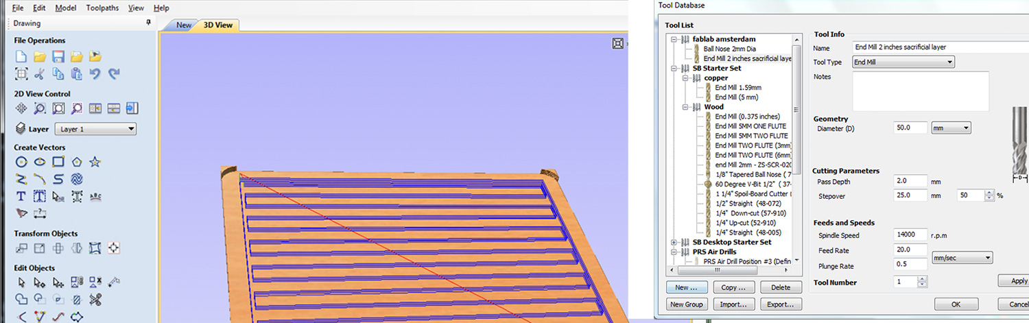
Make wood thiner Since the mill I want to use can only stick out 41 mm and the wood is 57 mm thick I have to make it thinner. Luckily we have an super mill of 50 mm across perfectly suited for this job. So I fixed the material with screws to the sacrificial layer and took 8 mm of from both sides. I just made a square in Vcarve and Used Pocket
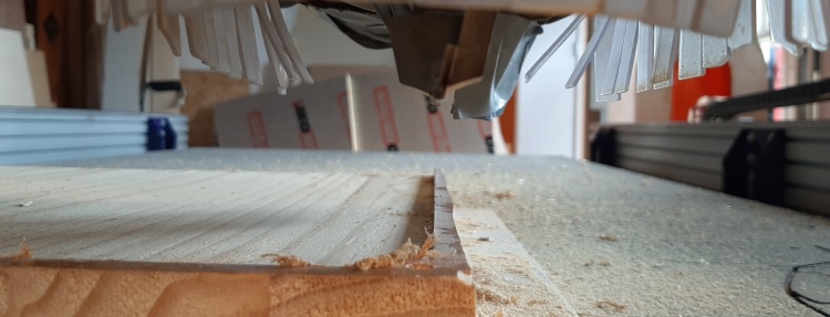
Roughing path After the roughing path I started with the finishing path. But within the first run the mill dived into the material and the mill broke.
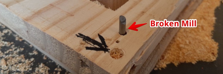
It took us (Henk an I) some time to figure out why the mill just went straight into the material and tried to move in -X direction. The reason was: missing roughing toolpath. The rouging toolpath was not made on two sides, the gap of my material was 5 mm, but V-carve decided this is not enough to drive a 4 mm mill in it for the roughing path. But for the finishing path is supposed not to be a problem according to V-carve…
This was solved by using an smaller mill. But than I had to start from the beginning, and 90% would be ‘air-milling’. So we came up with a plan: using the 2D drawing in V-carve I made a pocket and milled this with a 3 mm mill.
The 2D drawing was a success, so i started the finishing part. But the mill broke again! The mill just went into a part of the material. It some time to find out the roughing path was not made on this place.
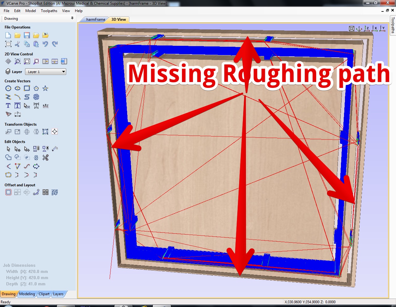
The reason is: V-carve will not make roughing parts where the model has no material on the z plane. But will make finisching paths from the same model on the places.
So I added a 0.01 mm base to my fusion model 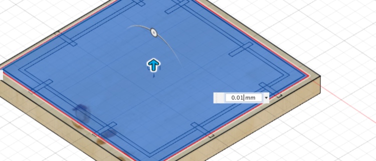
With this model VCarve made a perfect roughing toolpath… 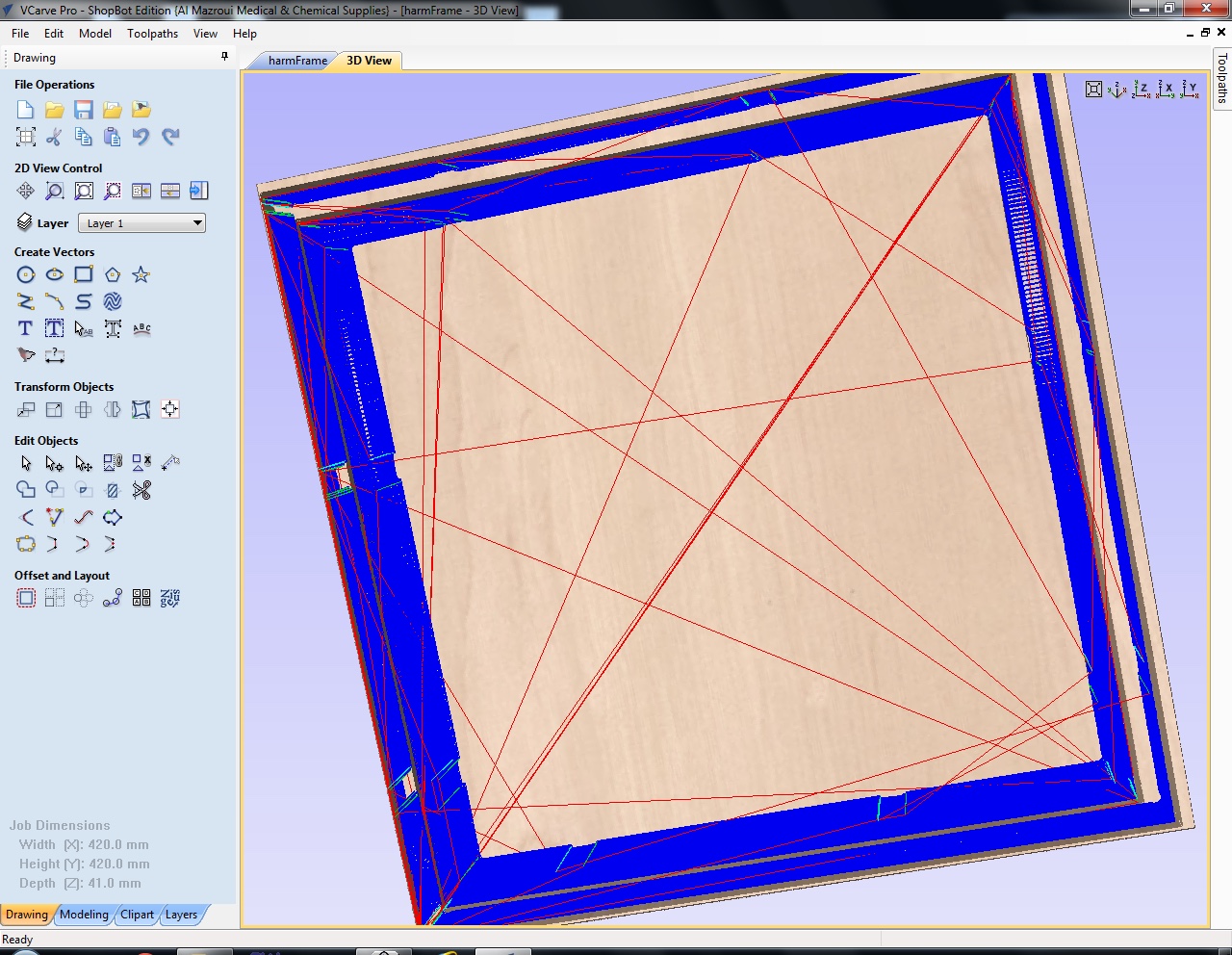
Designing the front glass (acrylic)
Since I tested with real glass and had the idea this glass was transferring heat and spreading it all over the painting I want to test with Acrylic.
Termal conductivity (κ)
- glass: 1.05
- Acrylic 0.2
I made round edges in the outside corners. Since the frame had round edged from the 3mm mill in the Inside corners. I cutted the acrylic 1 mm smaller than the inside of the frame, exact measurements would take me some sanding. 0.5mm on both sides will help me fit it.
Designing it in Fusion 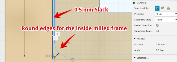
Making the front glass (laser cutter)
I used 3 mm acrylic and cut this on the laser using:
- speed 25
- 80 power
Making the passepartout
The passepartout is to keep the paint not touching the Acrylic, this to prevent heat flow. Second reason to use it: it makes the whole ‘painting’ look better.
Designing the passepartout
I just made the passepartout in illustrator
Laser cut the passepartout
the passepartout Used 1.1 mm museum board (Vlieger Papier)
- speed: 80
- power: 50
Making the backboard
Designing the backboard
Based on the illustrator design
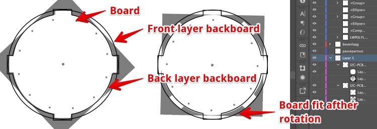
I want to house the PCB’s in the backboard. So the PCB’s and heatwires will press against the paper and paint. I came up with a kind of B
Making the backboard - Laser Cutter
the backboard - hard cardboard
- speed 25
- 70 power
the backboard - soft cardboard 3 mm
- speed 60
- 90 power
the backboard - soft cardboard 1.5 mm
- speed 60
- 50 power
the paper (print)
- speed: 80
- power: 20
Case holding the Nichrome wires PCB
The PCB will be fitted in the backboard using a Bayonet fitting. 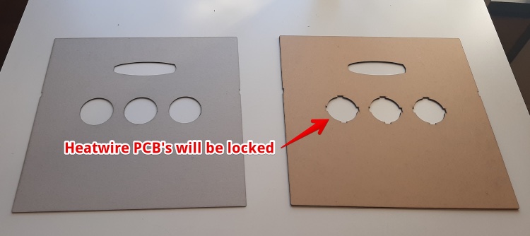
Case holding the Microcontroller PCB
Backboard is also the housing for the PCB’s Made in Fusion, added to Illustrator 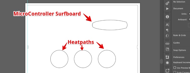
Make (the painting) a copy of the print
I used the print in the painting we have in the kitchen. This is an IKEA print, the original painting is made by Corinne Dalle Ore.
I scanned the print and decided the original tomatoes are not big enough. I changed them.
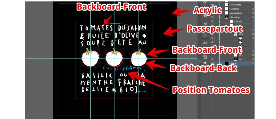
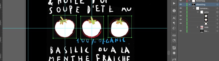
Since the themo ink is not sticking on the laserprinter toner, I had to print ‘empty’ tomatoes. I used Photoshop to remove the red. And made one big illustrator file to have the:
- Laser cutout - Passepartout cutout (later cutter)
- Laser Cutourt- Backboard 2 (lock to house the PCB boards)
- Laser cutout- Backboard 1 (against painting)
- Laser Print - Position of the tomatoes and print within passepartout
Microcontroller board (ESP-12F)
Since I need to get the weather data from the internet I desired to use a WiFI microcontroller.
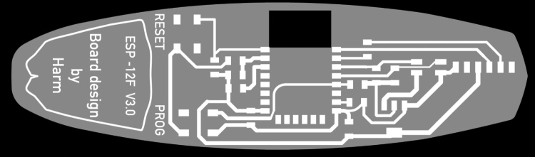
Design the MC board (EPS-12F surfboard)
I have created a ESP-12F board But I needed some iterations:
- The pull-up resistors are missing
- There is no separate FTDI header
- I want an NTC to take room temperature and use this data for the heatpath power
- I wanted to have a more personal
In eagle I changed the schematics to match my requirements. But while trying to import images in EAGLE i found out this is close to impossible. So I decided to do the ‘graphic’ design part in Photoshop.
This is the work-flow:
- Create a PSD document with 1000 pix/INCH
- In Eagle: Export Image > Tick both ‘Monochrome’ & ‘Clipboard’
- Resolution = 500DPI !!! This is the bug of Eagle on Mac, since mac Retina screens double the resolution
Milling the board
When milling the board I changed the dept to 0.08 for the traces.
Fitting all the parts together
Heating the paint
During the past 18 weeks I have been searching for a way to electronically heat paint. You can read all about this on the dedicated page about the heatpaths.
Make the I²C heatwire board
Since the MC board has only a limited GPIO’s I looked in way of driving the boards using less than 37 wires i will need to power 36 heatwires. I made a shift register working in week 10 & 14, I looked into the 2811 led driver chip in week 14, tested Multiplexers in week 11 and 14 and looked at Charlyplexing. In week 14 I desided to use a I2C chip and made an board for it.
This I2C board worked at the end but has a few problems:
- There is no I²C Address selection method
- While uploading code I sometimes notices one of the wires got hot a long time
- The board had no nice way to fit in the frame
- The outer holes are too big (nichrome wire is just 0.17mm).
- The inner (central) hole was to small
I changed the design and milled my first board. While milling I looked at my design and noticed the gnd was not connected. 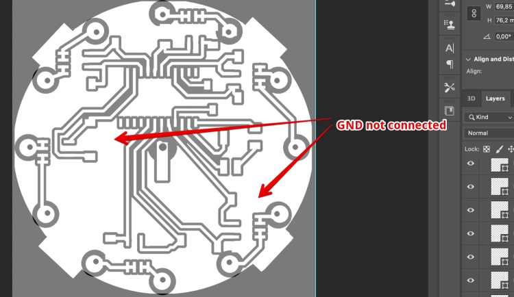
So I added a 0 ohm resistor to the second board. 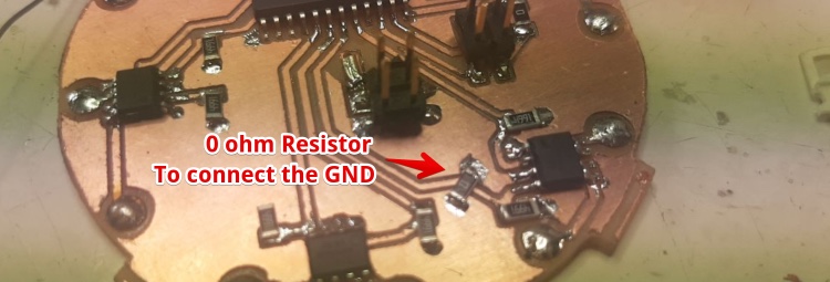
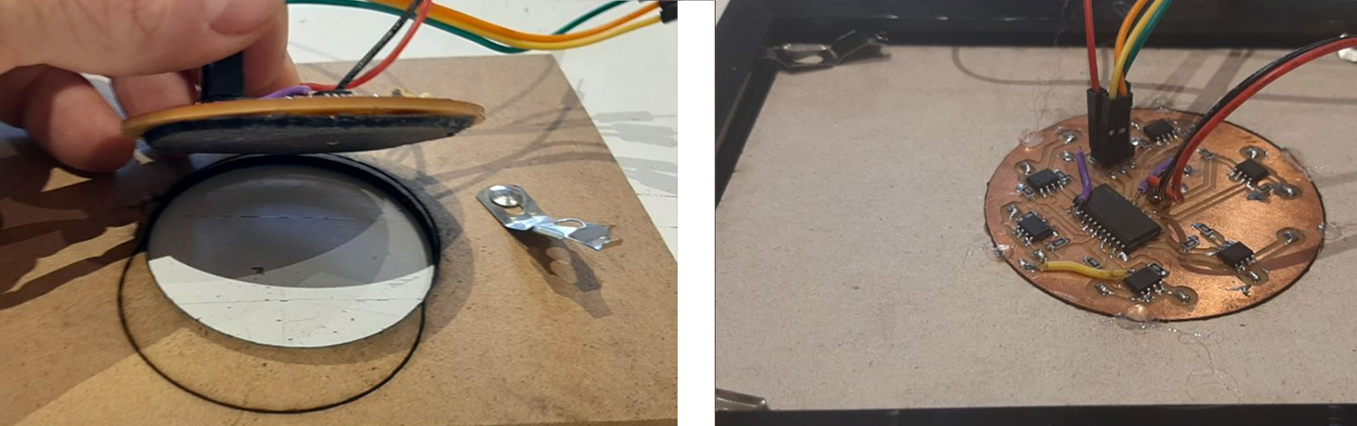
And used a 1mm rivet to feed the 12 wires trough the board 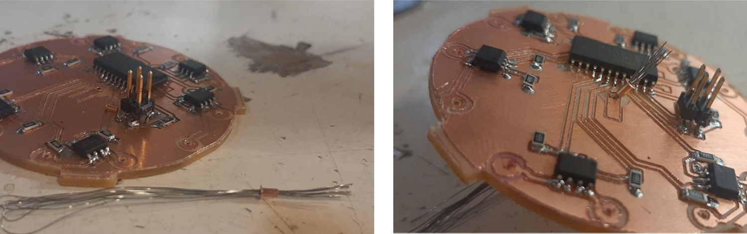
Than make flat, and cut the rivet to keep the wires in place. Than solder 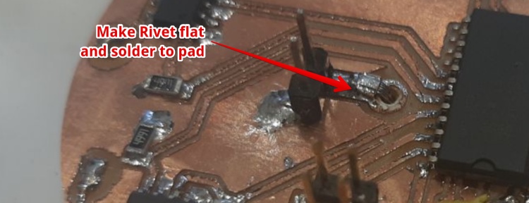
On the other side pull the wires trought the 12 holes and pull around the corner to keep stretched (a bit) 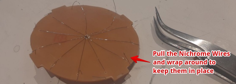
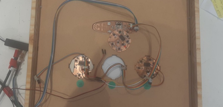
The result, 3 PCB’s with 36 separate heatwires in total 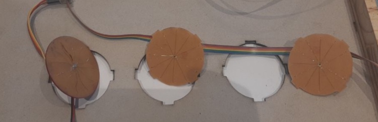
Testing the complete project. heatwires in the frame
I used this testing code to address all the pads
When testing I noticed a burn smell. I took the power away and looked at the back of the painting and saw some smoke.
I took the smoking heatpath out (using the bayonet fitting) and could see a clear burn in the paper. 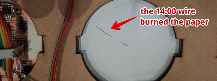
I measured the resistance between ground and the connection of the heatwire. It was only 2 ohm. I looked close and the copper of the wire was close to the common ground. I scraped a bit of copper away. Now the resistance was more than 10K. 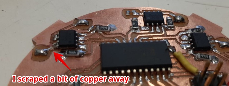
1. Code for the MC board: Get the weather data from the web
Connect the ESP via WIFI and get the weather data I did in the ‘Network week’. And prior the Fabacademy I made an private API to get data from the internet in PHP. This code runs on a web server and converts the HTML from a website to Json. This Json and looks like this (the real json contains 36 hours of data. You can find it here
{
    "voorspellingen": [
      {
        "dag": "16",
        "uur": "10",
        "wind": "8",
        "gust": "11",
        "dir": "176"
      },
      {
        "dag": "16",
        "uur": "11",
        "wind": "11",
        "gust": "14",
        "dir": "184"
      },

     {
        "huidigMaand": "11",
        "huidigUur": "8",
        "huidigMinuten": "52"
      }
    ]
  }
I connected to the internet using this code (in setup)
  /******** Connect WIFI *******/
  WiFi.begin(ssid, password);
  while (WiFi.status() != WL_CONNECTED) {
    delay(1000);
    Serial.println("Connecting...");
  }
and this function called in the loop
//================= FUNCTION Get winddata ============///
void winddataOphalen() {

  if (WiFi.status() == WL_CONNECTED) {
    HTTPClient http;  //Object of class HTTPClient
    http.begin(JsonURL);      //get de html
    int httpCode = http.GET();

    if (httpCode > 0) { //If it gets anything, do everyting below
      String payload = http.getString();  // Get the  response
      //Serial.println(payload);
      voorspellingenDataArray(payload);
    }
    http.end();   //Close connection
  }
}
I downloaded the ArduinoJson library described here. And used the Json example code from the example that came with the ArduinoJson library.
I calculated the ‘Memory pool size’ (useing their tool)(https://arduinojson.org/v6/assistant/) and this is the code called from “winddataOphalen()” (code above):
void voorspellingenDataArray(String jsonString) {
  //----- create Json Array from string
  deserializeJson(doc, jsonString);
  JsonArray voorspellingen = doc["voorspellingen"]; //doc is a global variable
I print the data in the serial monitor using:
      Serial.print(" >30 paars");
    } else {
      Serial.print(" < 14kn blauw");
    }
    /* ------ Voor debuggen en testen ------------*/
    Serial.print(". Hour: ");   Serial.print(VoorspellingHour);
    Serial.print(" . Wind: ");   Serial.println(VoorspellingWind);
The module connects and displays the data, but crashes and restarts:
It took me some time to find out I called the function displaying data every loop cycle! I added delay within the loop:
  for (int x = 0; x < itemsArray - 1; x++) {
   delay (20); //Add this and NO MORE CRASH
Program for a I2C Heatwire board with PWM
In the output week I have been experimenting with PWM and got the I2C chip running. In my Final weeks I will:
- make code the PWM (les power consumption, same effect)
- make code PWM for multiple I2C boards
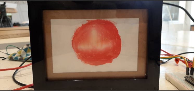
First test I2C board heating ink (in a photo frame)
My test with an frame I bought at the shop. The frame has a backboard I took out and used a 3mm version. Used the laser cutter to take the PCB board out. For now I used the heat gun to attach the PCB to the backboard. I connected my own ESP-12 board and uploaded the code.
I first tried to lasercut the original backboard with the frame, but was really scared to hit the metal parts. So I used an other 3 mm cardboard we had in the Lab. For this test I used a glue-gun to attach the PCB to the Backboard.
I Used a code I made in week 14
#include "clsPCA9555.h"
#include "Wire.h"

// 0 = 9 uur, 1 = 10 uur, etc
int uur[] = {0, 1, 2, 3, 4, 5, 6, 7, 12, 13, 14, 15};

int pulseLength = 10;

PCA9555 day1(0x20); //create an instance from object

void setup() {
  Serial.begin(9600);
  day1.begin();
  day1.setClock(400000);
  for (uint8_t i = 0; i <= 16; i++) {
    day1.pinMode(i, OUTPUT);
  }
}

void loop() {

  for (uint8_t i = 0; i <= 12; i++) {
    day1.digitalWrite(uur[i], HIGH); //HEATWIRE WILL BE POWERED
    delay(pulseLength);//20 aan en 20 uit is moooi
    Serial.println(i + 9);
    day1.digitalWrite(uur[i], LOW);
    delay(1);//pulse LOW

  }
delay (1000);


}
Hero Shot:
Debugging the I²C Heatpaths
I made 2 more heatpaths connected all 3 heatpaths. And ran the Arduino code scanning I²C addresses. But only the first heatpath shows up.
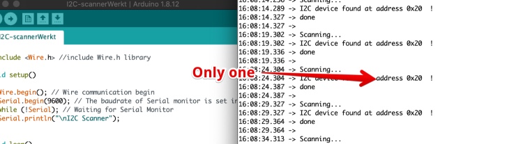
I looked at the boards, the schematics and the datasheet. And it turn out I got the Adressing wrong: 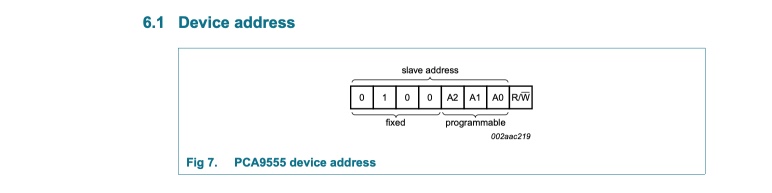
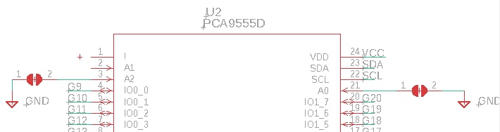
A0 and A2 should be connected to the VCC to change the address, NOT to GND like I designed.
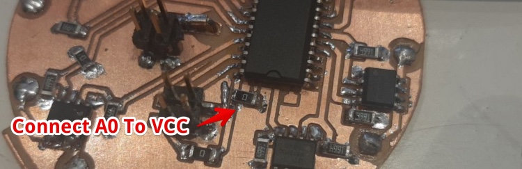
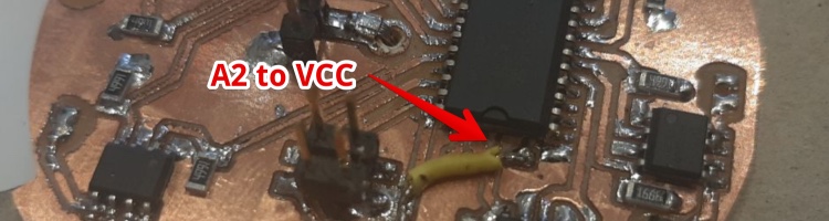
I left the first heatpath to default 0x20. And now all 3 heatpaths are found. So The wiring, chips, connections and addressing works!
Mini-HeroShot: 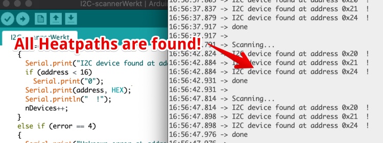
Transferring the heat (using a additive technique)
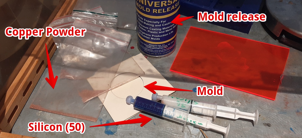
Since I don’t like the Idea of having heatwires pressing against the thin paper on the back, I have been experimenting and making heat transferring materials. In the Molding & Casting week I made heat-transferring paths using Epoxy and Copper powder. The problem with epoxy is: It is very hard and will not have a good contact when being pressed against the paper.
So for my final project heat-transferring silicon casts copper composites:
- Heat transfer should be optimum, so lots of copper powder
- Make it thin for more heat transfer
Setup:
- I Used the copper powder made by my father (see week)
- I used 4 mm Silicone 50 from Smooth On
- I cut two pieces of 3 mm thick cardboard
- Used a piece of Acrylic (or other hard straight material) to scrape the silicone flat
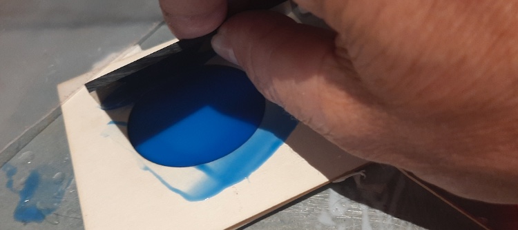
Steps
- Cut one circles of 60 mm in the cardboard with the laser cutter
- Stick the piece with the hole on the piece without a hole (see image below)
- Put in the silicone mixure (I used 4 ml total)
- make flat using a piece of plastic (See image below)
- Add copper powder till it not sinks in the silicon (not in the image below)
The result: 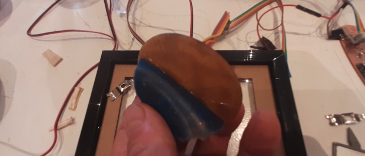
What kind of power supply do I need?
What is the minimum power supply I need, how can I optimize the Pulse With to waste a minimum power? To test this I used our Lab power supply.
This test is with the 31C Thermochromatic ink from SXCL and a 5V power supply
| Ampere | heating time (per wire in mS) | cooling down time (mS) | image |
|---|---|---|---|
| 0 A | none | none | 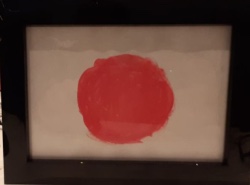 |
| 3.1 A | 7 | 1300 | 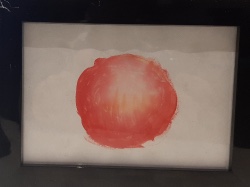 |
| 2 A | 30 | 1600 | 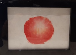 |
| 1.5 A | 40 | 1600 | 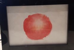 |
| 2 A | 40 | 1600 | 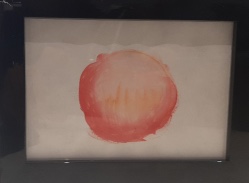 |
| 2.5 A | 40 | 1700 | 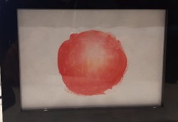 |
| 2.0 A | 50 | 1900 | 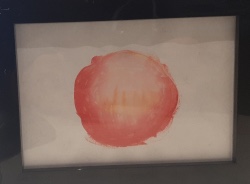 |
| 2.0 A | 60 | 2500 | 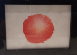 |
| 2.0 A | 80 | 2800 | 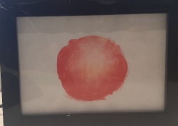 |
| 2.0 A | 80 | 3500 | 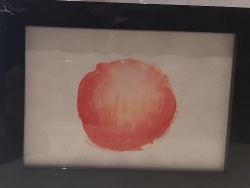 |
| 1.6 A | 80 | 2800 | 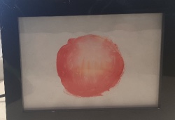 |
| 1.5 A | 80 | 2800 | 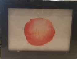 |
| 2.0 A | 80 | 2800 | 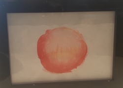 |
| 2.5 A | 80 | 2800 | 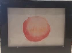 |
| 3.0 A | 80 | 2800 | 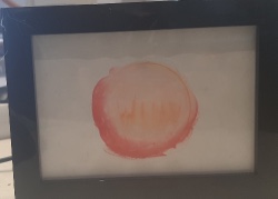 |
Can I see individual hours? The tests above shows I can power all wires. But I need to display the wind predictions per hour. So I tested powering the 9:00, 12:00 and the 15:00 hour wires. The result is OK. Inside temperature is 21Celcious.
Can I use an USB charger for the heatwire supply?
I have to consider the USB cable is not capable of transporting 3Amps since the wires are really thin. I had a strong phone charger at home and decided to strip a USB cable to connect this to the Heatpath mosfets.
This is the USB Phone charger I will use for the wires: USAMS 3A USB Phone Charger LED Display EU Plug Total Max 3A
2. Coding the MC board for the I2C board
I used a library to address the 16
When designing the board I decided to make the board more beautiful by using not the first 12 of 16 on the PCA9555. So I have to fix this in code. I made an array:
int wire[] = { 0,    1,   2,   3,   4,   5,   6,   7,   12,   13,  14,  15};
//  INDEX   0=9u,1=10u,2=11u,3=12u,4=13u,5=14u,6=15u,7=16u,8=17u,9=18u,10=19u,11=20u
Power a heatpath
  // ------------- Heatpath day 1
  for (uint8_t i = 0; i <= 12; i++) {
    if (i == 7 || i == 8 || i == 0) {

      day1.digitalWrite(wire[i], 1); //HEATWIRE WILL BE POWERED

      // 0=9u,1=10u,2=11u,3=12u,4=13u,5=14u,6=15u,
      // 7=16u,8=17u,9=18u,10=19u,11=20u
      Serial.print("index: ");      Serial.print(i);
      Serial.print(" - uur: ");      Serial.println(i + 9);
    }
    delay(pulseLength);
    day1.digitalWrite(wire[i], LOW);

  }
The complete code is here:
3. Combining the Json code and the I2C code
- I made the code getting data from the internet via Json and display this one by one in the serial monitor.
- I made code displaying data in the heatpath wires one by one
First I tried to simplify my heatwire code and ran into a strange error: 
I forgot that i runs from 0 to 12 = 13 wires… So I changed the code to:
for (uint8_t i = 0; i <= 11; i++) {
Here I decided to display wind forecasts from 10:00 to 21:00, I live 1 hour from the beach so I never be on the water at 9:00
When combining both working codes I took little steps. Almost every step worked (apart from a few typo’s and non existing variables). But It took me some time to separate the different lines of code and combine them under the function. Then I struggled a bit to get call the right functions at the right time, but this is what I came up with:
Now every cycle (in the loop) the wire activation is called. And I only call the Wifi, getJson and json to data every 15 minutes. The functions are called like this.
So every (loop) cycle (with the delay of wire-heating):
- voorspellingenDataArray(); //will heat wires according to the json data
- pulseCooldown = map(analogRead(A0), 366, 460, -5, 5); //will get the value of the NTC and add extra cooldown time
Every 15 minutes:
- winddataOphalen(); //will connect to the internet and get data from it
- voorspellingenDataArray(String jsonString) {//----- create Json Array from string
Bill of material
BOM Frame
| Name | Specs | Where to buy | times needed | Cost (one piece € ) | total costs |
|---|---|---|---|---|---|
| Wood for frame | Pinewood - old tabletop 40mm * 500mm * 500mm | Found at the dumpster | 1* | 0 | 0 |
| Backboard 3mm | Hardboard 3 mm | about every hardware store | 1/12* | 6,35 (for 2440x1220x3 mm) | 0,50 |
| Backboard 1.5mm | Cardboard 1.5 mm | Vlieger | 1 | 3,60 (for 550 x 800 mm) | 3,60 |
| Front ‘glass’ | Acrylic 400 x 400 x 3 mm | In the Fabacademy | 1 | 26,88 (for 800 x 800 mm) | 26,88 |
| Passepartout | 1.1 mm cartboard (museum papier) | Vlieger | 1 | 3,64 (for 500 x 800 mm) | 3,64 |
| Screws | PZ 1, 3 x 10mm | Gamma | 8 | 0.05 | 0.40 |
BOM 3 Heatpaths
| Name | Specs | Where to buy | times needed | Cost (one piece € ) | total costs |
|---|---|---|---|---|---|
| PCB material | FR4 - Single side! | From FabLab | 3 | 1 | 3 |
| Nichrome wire | FR4 - Single side! | Aliexpress | 1 | 3,0 | 3,0 |
| Dual MosFets | DMG9926USD | Digikey | 18 | 0,32 | 5,76 |
| 5K resistor | RES 4.99K OHM 1-4W 1% 1206 SMD | Standard FabLab inventory | 36 | 0,10 | 3,60 |
| 0K resistor | RES 0.0 OHM 1-4W 5% 1206 SMD- | Standard FabLab inventory | 4 | 0,01 | 0,04 |
| 2 x 2 connector | CONN_02X2-PINHEAD-SMD | Standard FabLab inventory | 6 | 0,5 | 3,0 |
| I2C chip 16 ports | PCA9555DSOT137-1_NXP-L | digikey | 3 | 1,55 | 4,65 |
BOM ESP-12F surfboard
| Name | Specs | Where to buy | times needed | Cost (one piece € ) | total costs |
|---|---|---|---|---|---|
| Capacitor 100nF | 100nF AP_UNPOLARIZEDFAB C1206FAB | FabLab inventory | 1 | 0,08 | 0,08 |
| Capacitor 10uF | 1CAP CER 10UF 35V Y5V 1206 | FabLab inventory | 1 | 0,15 | 0,15 |
| NTC | 10K R1206FAB | FabLab inventory | 1 | 2,50 | 2,50 |
| FTDI connector | CONN_06_FTDI-SMD-HEADER | Standard FabLab inventory | 1 | 0,25 | 0,25 |
| 2 x 2 connector | CONN_02X2-PINHEAD-SMD | Standard FabLab inventory | 1 | 0,5 | 0,5 |
| 3.3V regulator | SOT223”;”Voltage Regulator LM1117” | Standard FabLab inventory | 1 | 1,0 | 1,0 |
| ESP-12F | ESP8266-ESP12F | Standard FabLab inventory | 1 | 1,0 | 1,0 |
| Pushbutton | TACT 6.0 X 3.5, 2.5 MM H, 180GF | Standard FabLab inventory | 2 | 0,15 | 0,30 |
Power supplies
| Name | Specs | Where to buy | times needed | Cost (one piece € ) | total costs |
|---|---|---|---|---|---|
| Supply ESP-Surfboard | USB 5V 1Amp | Use any old phone charger | 1 | 0 | 0 |
| Supply HeatWires | USB 5V 2,5 Amp | I pad charger. Or buy any (I used the USAMS 3) | 1 | € 4,41 | € 4,41 |
Thermochromatic paint
THERMOCHROMIC SCREEN PRINTING INK GREEN 31°C, from SFXC € 5,47
Total costs € 62,12
Hero Time: My final project
Video showing my final project
My final poster 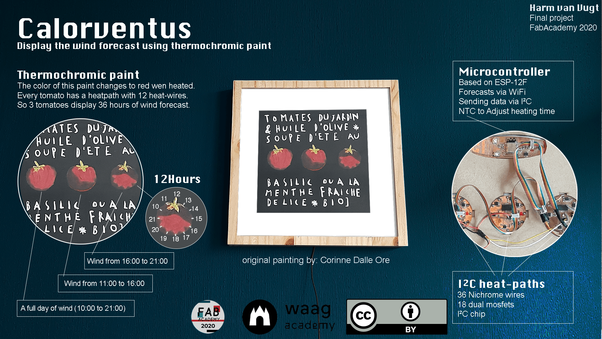
Files & conclusion
Arduino Code
- windTestData.json
- HeatPath testing code
- Connecting to json & WiFi code
- final Arduino code
- I2C-scanner code
Eagle Files:
Fusion 3D files
Illustrator file - for laser cutter
Final poster & video
Future improvements
- Make the tomatoes smaller (now the heatpath will only warm the centre)
- Interaction: to save power I tested with the radar sensor. The next spiral of this project I would add the radar sensor on the back. So the tomatoes only color if someone stands in front of the painting.
- Other heating: a >3 seconds powered wire will burn the paper. This is not a save option. Solutions:
- make some heating element only heats up till 50C. This could be done by
- Display multiple wind speeds: use multiple Termochromic inks with different temparatures, so I can display no wind/oke wind/perfect wind
Conclusion
- I was really well prepared for the final week by working towards this past 6 months
- At the end I ran into the problem I never had an perfect heated painting. So changing the color from green to Red Did not work
- But I’m very proud with the result!
- This is the end of Fabacademy, I will miss making things. I learned so much!