14 - Networking and Communications
How to get weather data into my project and send it to the heatpaths?
Assignments
- individual assignment: design, build, and connect wired or wireless node(s) with network or bus addresses
- group assignment: send a message between two projects
Page Index
- How to get wind data from the internet?
- Group assignment: send a message between two projects
- How send data to 36 heatwires?
- Create the I2C board
- Fire up my I2C board
- Final files & Lessons learned:
How to get wind data from the internet?
1. Connecting ESP-12 to the internet
I first tried to connected to my WiFi and download data from the internet.
I looked at the example codes from Arduino and tried “File > Examples > ESP8266WIFI > WiFi Client Basic” I entered my STASSID (WIFI ID) and STAPSK (Wifi Pass) and uploaded the code. No errors, but when I opende the Serial Monitor it gave my a lot of strange sings, I fixed this by changing the baud rate for communication between the board and the ESP to 115200.
The serial monitor only presented dots 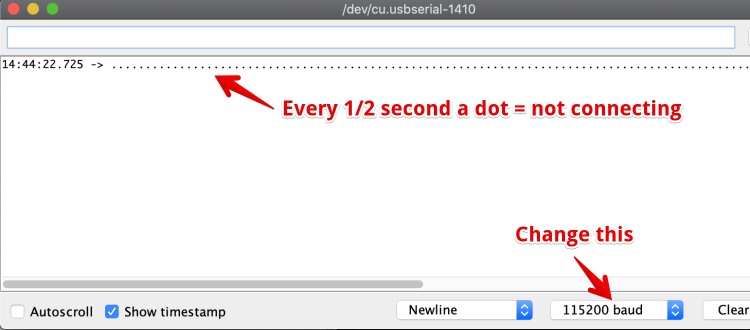
Looking in the code, this part triggered the continuous dots.
  while (WiFi.status() != WL_CONNECTED) {
    delay(500);
    Serial.print(".");
  }
According to article post about ESP wifi problems the esp8266 is not able to connect with 5Ghz WiFi. It is all I have in my workspace, so i tried to connect to my Hotspot on the phone. And It works!
Working code, connects with my WiFI, reads an URL and displays the content in the URL 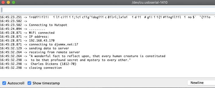
Lessons learned:
- ESP 8266 Only works with 2,4GHz wifi
- or just RTFM, it is in the datasheet :-)
2. Read weather data from the internet
Weather data is available from several sources. I used google to find the ‘biggest’ https://openweathermap.org/api. It is available in XML or Json. I registered for a key and I should get the data when using pro.openweathermap.org/data/2.5/forecast/hourly?q={amsterdam}&appid={MY SECRET KEY HERE} I got an error:
 Following the link, this error has several reasons, but all about the API key. The only plausible problem could be: Your “API key is not activated yet. Within the next couple of hours”.
I tried another option, maybe the hourly predictions are only for the pro subscription.
api.openweathermap.org/data/2.5/forecast?lat={53}&lon={4}&appid={1da6f2043af20db055b32e5ae1e269d7}
Again, same error 401
While waiting for the API activation I tried to use the example json file available here: https://samples.openweathermap.org/data/2.5/forecast?lat=35&lon=139&appid=439d4b804bc8187953eb36d2a8c26a02
To do so I followed the Instructables how to Read Json with ESP’s
But using the example code in this post did not work; the ESP was not connection to the WiFi Anymore. The Serial monitor gave no error, just the message: 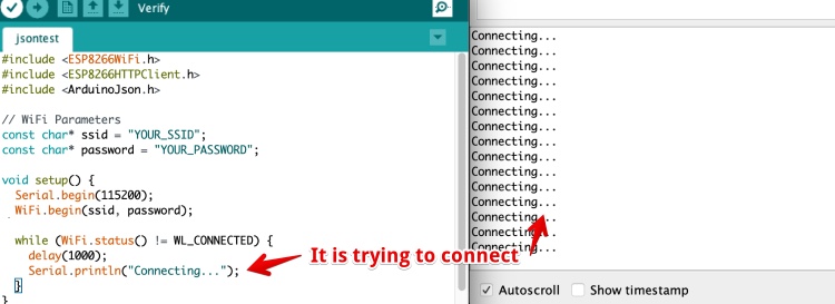
I tried the previous “WiFi Client Basic” code from the Arduino examples menu, this still works. So nothing wrong with my hotspot or wrong pass. In the comments of the post people are complaining the code does not work anymore.
According to the first comment the Instructables post is more than two years old. I hate Instructables for not showing the date of the article! It is just not possible to find out how old a post is, apart from deducting this from the comments.
I looked in the examples from Json in Arduino (File > Examples > ArduinoJSON > BasicHTTPClient) this code uses an Ethernet connection to grab the Json from a server.
In the original example code it was mentioned “It uses the Ethernet library, but can be easily adapted for Wifi.” I replaced the Ethernet code parts for the WiFi Code: 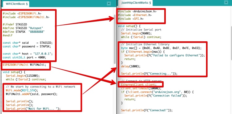
Hero shot: 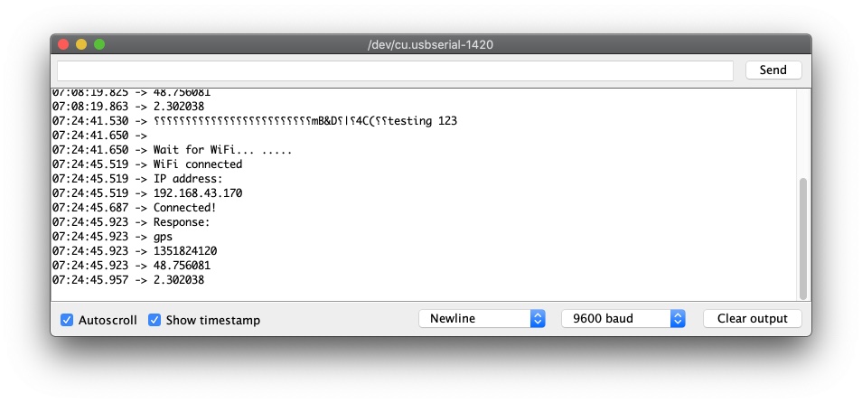
Group assignment: send a message between two projects
Since we are not physical together we tried to send and receive data over the internet to each other. I tried to read data from Hyeji over the internet.
read the overview of our group assignment
Hyejin gave me another Json URL to test with: https://jsonplaceholder.typicode.com/todos/1
I separated this URL and changed these lines:
if (!client.connect("jsonplaceholder.typicode.com", 80)) {
  client.println(F("GET /todos/1 HTTP/1.0"));
  client.println(F("Host: jsonplaceholder.typicode.com"));
And got a response, but not what I expected. only Zero’s
10:00:31.027 -> Connected! 10:00:31.170 -> Response: 10:00:31.170 -> 10:00:31.207 -> 0 10:00:31.207 -> 0.000000 10:00:31.207 -> 0.000000
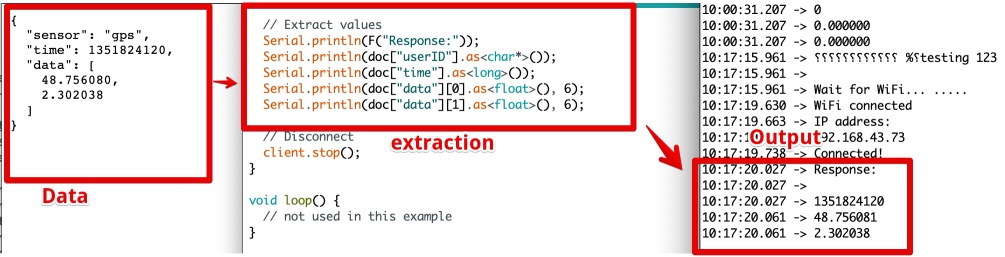
How to get Data from the Json file?
To understand how the Json works I read trough the Explanation of Monzilla
I compared the Json, the code and the output of my working example
I changed the ‘extract values’ to match the new JSON.
The hardest part was to find out the type:
.as<long>());
.as<float>(), 6);
.as<char*>());
With the help of this table I found working types: 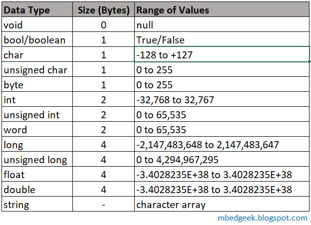
I Got a sensible output!!
Hero shot: 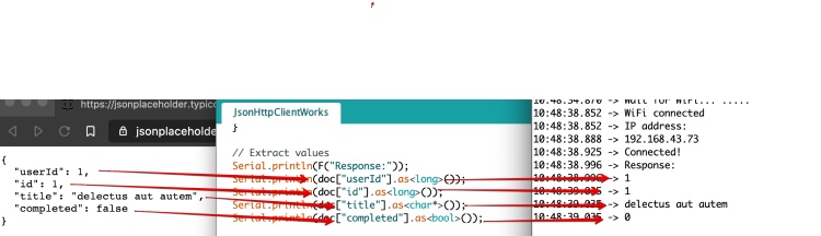
Now Hyejin made an Json file for me, to be able to connect between our two projects. This is the Json file. It looks like this (in case if she removes it from the server in the future): {"name":"harm","buttonStatus":false}
I succeeded to Read the button status from the file. Using the serial monitor of Arduino.
The Electrosome tutorial
Hyejin suggested me to look at the Electrosome tutorial about Json and ESP8266 and I changed the code according to this tutorial.
But the example was for another version of the Json library: 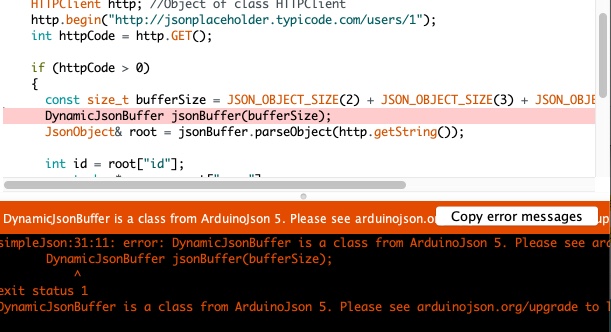
Problem: Code for the old ArduinoJson Library
I tried to fix this by rewriting the combined code by
- adding #include
- replacing ‘http’ by ‘client’
But the way it gets the JSON from the server is just really different (If I understand correctly) so combining these codes was not working. I went back to the working code and tried to get it to regularly get data from the server. Now it is only getting data during the ‘setup’.
Reading data from Hyejin over the internet
In the meantime Hyejin managed to finish the write part on her server. She told me I can change the buttonStatus value by executing this in Terminal:
curl --data "name=harm&buttonStatus=false" https://groupapi-fabacadey.herokuapp.com/buttonStatus
curl --data "name=harm&buttonStatus=true" https://groupapi-fabacadey.herokuapp.com/buttonStatus
I moved everything exempt the WiFi Connecting part from Void Setup() to Void Loop(), and added an if statement to check if the value in the json was true/false.
When the buttonStatus in the Json on the server is true the led goes on. If false it turns off.
The final code to connect to WiFi, get data via URL, load the data, make the data readable
#include <ArduinoJson.h>

#include <ESP8266WiFi.h>
#include <ESP8266WiFiMulti.h>

#ifndef STASSID
#define STASSID "Hutspot"
#define STAPSK  "88888888"
#endif

const char* ssid     = STASSID;
const char* password = STAPSK;

ESP8266WiFiMulti WiFiMulti;

void setup() {
  pinMode(D0, OUTPUT);

  // Initialize Serial port
  Serial.begin(9600);
  Serial.print("testing 123");

  // connecting to a WiFi network
  WiFi.mode(WIFI_STA);
  WiFiMulti.addAP(ssid, password);

  Serial.println();
  Serial.println();
  Serial.print("Wait for WiFi... ");

  while (WiFiMulti.run() != WL_CONNECTED) {
    Serial.print(".");
    delay(500);
  }

  Serial.println("");
  Serial.println("WiFi connected");
  Serial.println("IP address: ");
  Serial.println(WiFi.localIP());
}

void loop() {
  // Connect to HTTP server
  WiFiClient client;
  client.setTimeout(10000);
  if (!client.connect("groupapi-fabacadey.herokuapp.com", 80)) {
    Serial.println(F("Connection failed"));
    return;
  }

  Serial.println(F("Connected!"));

  // Send HTTP request
  client.println(F("GET /buttonState/harm HTTP/1.0"));
  client.println(F("Host: groupapi-fabacadey.herokuapp.com"));
  client.println(F("Connection: close"));
  if (client.println() == 0) {
    Serial.println(F("Failed to send request"));
    return;
  }

  // Check HTTP status
  char status[32] = {0};
  client.readBytesUntil('\r', status, sizeof(status));
  // It should be "HTTP/1.0 200 OK" or "HTTP/1.1 200 OK"
  if (strcmp(status + 9, "200 OK") != 0) {
    Serial.print(F("Unexpected response: "));
    Serial.println(status);
    return;
  }

  // Skip HTTP headers
  char endOfHeaders[] = "\r\n\r\n";
  if (!client.find(endOfHeaders)) {
    Serial.println(F("Invalid response"));
    return;
  }

  // Allocate the JSON document
  // Use arduinojson.org/v6/assistant to compute the capacity.
  const size_t capacity = JSON_OBJECT_SIZE(3) + JSON_ARRAY_SIZE(2) + 60;
  DynamicJsonDocument doc(capacity);

  // Parse JSON object
  DeserializationError error = deserializeJson(doc, client);
  if (error) {
    Serial.print(F("deserializeJson() failed: "));
    Serial.println(error.c_str());
    return;
  }

  // Extract values
  Serial.println(F("Response:"));
  Serial.println(doc["name"].as<char*>());
  Serial.println(doc["buttonStatus"].as<bool>());

  bool buttonS = doc["buttonStatus"].as<bool>();

  if (buttonS == 1) {
    digitalWrite(D0, HIGH);
  } else {
    digitalWrite(D0, LOW);

  }

  // Disconnect
  client.stop();


  delay (10000);
}
Superhero shot
How send data to 36 heatwires?
I need to drive 36 wires, consuming each 200 mA (guessing) so I need to multiply my outputs too. I have been experimenting during the past weeks with some, this week I give an overview and hopefully a final solution.
- Multiplexer, Read all about it in week 11
- Shift register
- WS2811 - Serial addressable (LED) ic This is a kind of shift register. You address an output with just one wire.
- I2C
- CHarlieplexing
- Other microcontrollers
1. Multiplexer to multiply the GPIO’s
Conclusion from week 11: I connected the multiplexer and got it to work, But it didn’t work as expected. The multiplexer only powers ONE output per time. And I need to be able to power all outputs at the same time. So it could be an option, but not the best I think Multiplexer, Read all about it in week 11
2. Shift registers
I learned a lot from website of Last Minute Engineers and copied this animation. It shows how a 8 bit shift register works. 
I found the datasheet of the TLC6C5912PWR it is a 12 bit shift register, if I want to display 12 hours a day and 3 days i just need three, and every board can have its own shift register.
Breadboard test Shift register
Since The (Covid) lock-down keeps me away from the FabLab I ordered some trough hole shift registers to test with a breadboard. It is a 8bits 74HC595 shift register. I used the datasheet to get the pins right.
I followed this manual to get it running. I struggled to get the pins right. In the datasheet the pins are called:
- RCLK
- SER
- SRCLK
- SRCLR
in the arduino code is called
- ds
- stcp
- shcp
When I got the pins right the example code worked, leds went on and off. I mistake the First output (QA) and thought this is bit 0. But it is bit 7.
I simplified the example code to understand it better:
int latchPin = D1;  // pin 12 of 74HC595
int clockPin = D2; // pin 11 of 74HC595
int SER_pin = D4;  //  pin 14 of 74HC595

byte leds = 0;    // Holds the witch of th 8 OUTPUTS are currently  on or off


void setup()
{
  pinMode(latchPin, OUTPUT);
  pinMode(SER_pin, OUTPUT);
  pinMode(clockPin, OUTPUT);
}

void loop() {
	leds = 0; //all leds off
  updateShiftRegister();

  delay(500);
  bitSet(leds, 7); //this is QA on the Shift register and
  bitSet(leds, 6); //this is QB
  bitSet(leds, 5); //this is QC
  updateShiftRegister();
  delay(500);

}


void updateShiftRegister()
{
  digitalWrite(latchPin, LOW);
  shiftOut(SER_pin, clockPin, LSBFIRST, leds);
  digitalWrite(latchPin, HIGH);
}
But how to switch one single led off?
It is so different from what I expected: bitSet(leds, 6); Leds is = 0 , so in his code I would set bit 6 to 0.
But this produced this error: 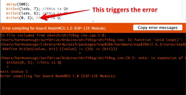 ‘#define bitSet(value, bit) ((value) |= (1UL « (bit)))’. I found out
 bitSet is a ‘macro’. If I find the time I will look what a macro in Arduino is. But for now I just want my individual Leds to go off.
I found in this video explains how setting and clearing bits worked
So I used ` bitClear(leds, 5);` to set a bit to ‘0’, this worked! And created this working code:
int latchPin = D1;  // 12 Latch pin of 74HC595
int clockPin = D2; // 11 Clock pin of 74HC595
int SER_pin = D4;  // 14 Data pin of 74HC595

byte leds = 0;    // Holds the wich of th 8 OUTPUTS are currently  on or off


void setup()
{
  pinMode(latchPin, OUTPUT);
  pinMode(SER_pin, OUTPUT);
  pinMode(clockPin, OUTPUT);
}

void loop() {

  ////LEDs OFF
  //leds = 0; //ALL off
  updateShiftRegister();


  for (int x = 7; x >= 0; x--) {
    bitSet(leds, x);
    updateShiftRegister();
    delay(200);
    bitClear(leds, x);
    updateShiftRegister();
    delay(200);
  }
}


void updateShiftRegister()
{
  digitalWrite(latchPin, LOW);
  shiftOut(SER_pin, clockPin, LSBFIRST, leds);
  digitalWrite(latchPin, HIGH);
}
Hero Shot
3. Use the I2C protocol to communicate with my Heatwires
Since the I2C chip for the board I designed (see below) is not delivered I can not test my own board with I2C. The only I2C I have is an Oled and an ESP-12F and a NodeMCU board.
I looked up how the I2C worked in the datasheet of the esp8266 chip not module.
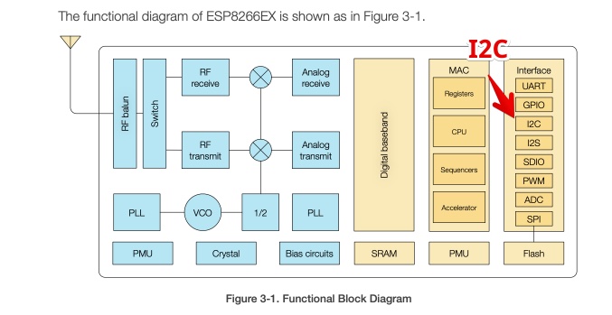
This are the connections: 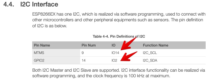 And it states “ I2C interface functionality can be realized via software programming…”
I don’t know what this means, could it be done by Hardware?
Looking for answers I fount answers on Edaboard I found a nice explination:
“Hardware I2C uses a piece of logic in the chip to automatically drive an I2C compatible output. You basically just throw your data at a register and it pretty much does the rest.
Software I2C requires the processor to basically repeat the operation of the inbuilt logic. Therefore your program has to do a lot more to output the connection. The upside to this is you are no longer tied down to which specific I/O pins you have to use.”
My conclusion Hardware I2C can be very hard, but it is faster. If I use software I2C it is more flexible. I just hope I get my Hardware 12C chip running when the board is ready (see next chapter). If I Can’t get it working I have to make a board for a multi GPIO (>16) Microcontroller with I2C support.
Test I2C with two NodeMCU’s
I followed this post on electronicWings
According to the information on
I2C bus is popular because it is simple to use, there can be more than one master, only upper bus speed is defined and only two wires with pull-up resistors are needed
Since I have none I will use the internal pull-up resistor
I connected the Node’s by using this manual
But this code is for one Uno and one NodeMCU, so I changed the setup code for the Master to:
void setup() {
 Serial.begin(9600); /* begin serial for debug */
 Wire.begin(D1, D2); /* join i2c bus with SDA=D1 and SCL=D2 of NodeMCU */
}
But nothing was seen on both the master or slave side!
I tried to scan for an I2C device, and used the I2C Arduino scanning code in this website
And no result
Test if I2C scanner is working
I doubt my method of scanning for I2C devices. So I tried the only other I2C device I have at home: A OLED screen. And connected this: 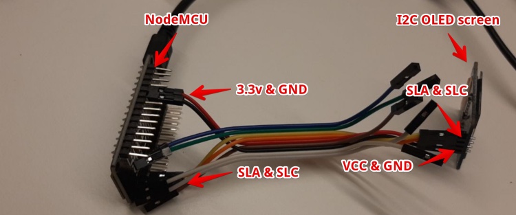
This worked like a charm: 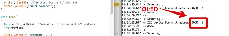 The only strange thing is the Address. The Serial monitor shows 0x3C the hardware the option to choose between 0x78 or 0x7A (done by removing the wire bridge?)
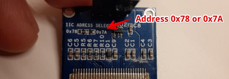
Since the SDA and SCL should be pulled high according to all documentation I found. I used a breadboard and two 10k resistors and connected them to VCC (3.3V) 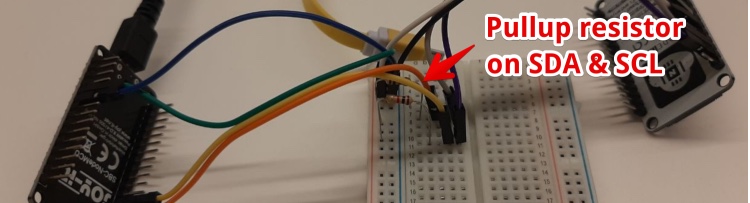
Now it noticed a I2C board was connected. But the address looked almost random 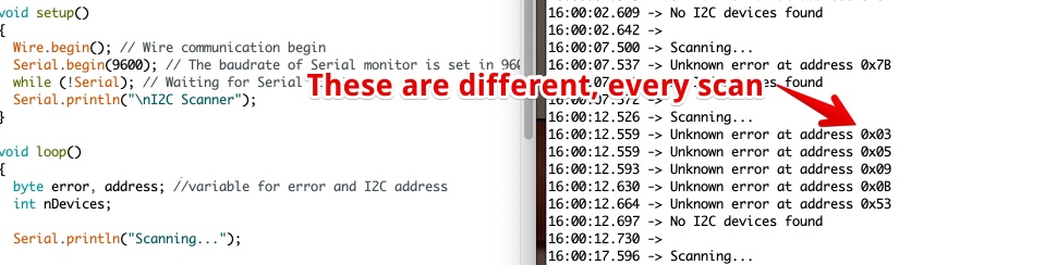
Is my I2C scanner working well?
I connected a 3-Axis Accelerometer, the Oled Display and the NodeMCU (I2C slave). Using a Breadboard. The result is strange: 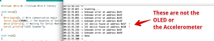
When only connection the Accelerometer and OLED the readout Is fine. 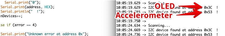
Can I display the communication between the I2C master master and slaves?
To see what is happening, it would be nice if I had access to a Oscilloscope or logic analizer. Since I don’t I try to read the levels using an Analog input and use the Plotter of the Arduino IDE.
Needed:
- NodeMCU 1: with 210 UART (In Arduino IDE: USB-to-UART)
- NodeMCU 2: with 340G UART (in Arduino IDE: USB-serial-1413)
- Pull-up resistor (input A0)
- I2C O-LED
- I2C Accelerometer
Connections:
- Connect both to USB (via USB Hub is best, to make sure GND’s are connected)
- Node 1: Connect SLA from Node 1
- Node 2: Connect a pull-up resistor (I used 1k, 4,7K could be better) between A0 and VCC
Code for the I2C scanner (Node 1)
#include <Wire.h> //include Wire.h library

void setup()
{
  Wire.begin(); // Wire communication begin
  Serial.begin(9600); // The baudrate of Serial monitor is set in 9600
  while (!Serial); // Waiting for Serial Monitor
  Serial.println("\nI2C Scanner");
}

void loop()
{
  byte error, address; //variable for error and I2C address
  int nDevices;

  Serial.println("Scanning...");

  nDevices = 0;
  for (address = 1; address < 127; address++ )
  {
    // The i2c_scanner uses the return value of
    // the Write.endTransmisstion to see if
    // a device did acknowledge to the address.
    Wire.beginTransmission(address);
    error = Wire.endTransmission();

    if (error == 0)
    {
      Serial.print("I2C device found at address 0x");
      if (address < 16)
        Serial.print("0");
      Serial.print(address, HEX);
      Serial.println("  !");
      nDevices++;
    }
    else if (error == 4)
    {
      Serial.print("Unknown error at address 0x");
      if (address < 16)
        Serial.print("0");
      Serial.println(address, HEX);
    }
  }
  if (nDevices == 0)
    Serial.println("No I2C devices found\n");
  else
    Serial.println("done\n");

  delay(5000); // wait 5 seconds for the next I2C scan
}
Code for the Serial Plotter Node 2 (340G UARTchip): Arduino > File > Examples > Basic > AnalogReadSerial Change:
Serial.begin(9600);
to
Serial.begin(115200);
You can ‘see’ both Nodes at the same time 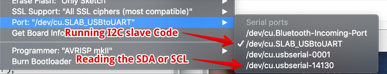
Open the Serial Monitor and Serial Plotter at the same time:
- in Arduino IDE: Select the port for Node1 (USBtoUART)
- Open the serial monitor
- Select the port for Node 2 (14130)
- Open the Serial Plotter (Arduino > Tools > Serial Plotter)
- Make sure You set the baud rate for the Node 1 to 9600 (in both code and the serial monitor)
- Make sure you set the baud rate for the Node 2 to 115200
Open serial Monitor on Node 1 and open Serial Monitor on Node 2. At a speed of 5% of the original
- Embed video

Mistakes & lessons learned:
- Connecting I2C between hardware is easy
- Connecting an ESP8266 as slave Is hard (I did not succeed)
- I need to add pull-up resistors to my I2C heatwire board
- I need to find out if the Addresses on my ordered I2C chips are different (or if i can change them)
- You can not measure the entire I2C communication using the Serial plotter
Update during the regional review
During the regional review Florent Lemaire showed his work. He tried to get a ESP6266 working as a I2C Slave too. He failed and found out this is a problem in the library. Jump to the section of Florent Showing It is a Bug
The bug is described here: https://github.com/esp8266/Arduino/issues/3046
WS2811 - Serial addressable LED chip
I have been ledstrips and Arduino. The ledstrips I used are know as Adafruit NEOPIXELS. But it took me a lot of time to find out that the WS 2812 a 5050 RGB LED is together with a chip. The chip is integrated inside the 5050 package. This chip is like the WS2811 (only smaller) and the LED and chip is generally referred to as WS2812 or Adafruit NEOPIXELS. I bought WS2811 chips via AliExpess.
Read more about WS2811, WS2812, WS2813, 5050 chips and Neopixels
Datasheets:
- 5050 LEDS SMD version of RGB LED
- WS 2811single chip without the LED)
- WS 2812B the RGB LED + Chip on a ledstrip
The WS2811 and WS2812B: 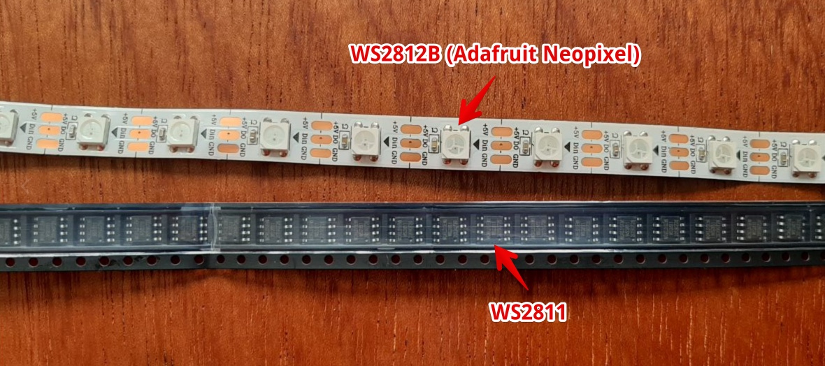 You can say A WS2812B is a 5050 RGB LED with integrated WS 2811 chip
How to use a WS2811 to drive MOSFETS?
From the Datasheet of the WS 2811 comes my plan is to drive MOSFET’s and not LED’s 
Since I can’t find a footprint for the 2812 I will change a footprint of a dual MosFet
Conclusion: I ordered this IC via Aliexpress and received it. I would like to make an board with this chip, but it will need 4 WS2811 IC’s for one Heatpath and 4 extra resistors. So if I have extra time…
3. Multiple microcontrollers?
Afther talking to the Agrilab Fabacademy teacher Luc Hanneuse, he told me there are a lot of ways to fix the extending of the IO’s. He seaid that “Neil would probaly solve this with extra microcontrollers”. So i looked into easy to programm microcontrollers with lots of PIO’s.
Afther a converstation with Lucas Steenhuis ( an expert in interactive installateions ) het said he would take multiple Arduino’s and communicatie via RT-TX to send the data to every microntroller. So i made this sketch, containing:
- One Wifi-Microcontroler (ESP?) to receive WiFI and convert the input data (json?) to hourly activated wires
- This ESP is connected via RX/TX to 3 microcontrollers
- The Microcontrolers each have more than 12 GPIO’s.
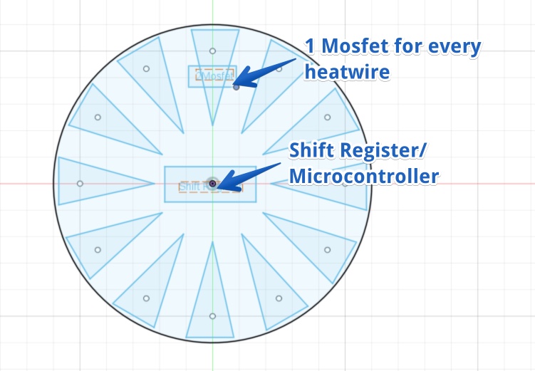
- For every 12 hours (one tomato) one PCB with a Microcontroller and Mosfet’s
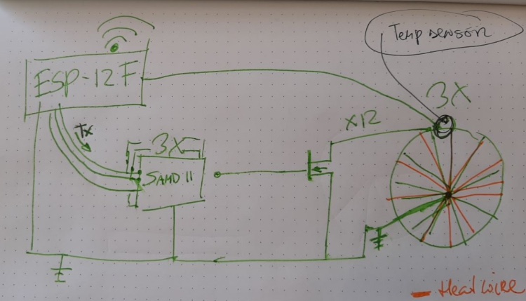
A more concrete drawing in Fusion, but fusion is not suitable. So I have to redraw in Eagle. But as a concept this is the idea
The disadvantage of multiple microcontrollers is the code. I have to upload code to these controllers, for this these microcontrollers should be accessible. So if I want a very compact package and be flexible I would like to stick to one microcontroller.
Create the I2C board
I looked of a 12 output chip, but this seems to be not available, so I spend a long time searching for a I2C with a footprint suitable for hand soldering.
Before (in output week) I made a board where I manually placed the components in a circle. This was not exact so I made the holes really big. Since I have less space using the I2C board I have to place the holes and connectors very exact.
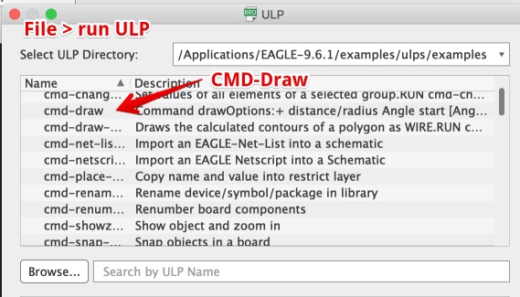
This is not easy, but I found an video explaining components in a circle with eagle how to place components in eagle in a circle
Steps:
in eagle PCB: File > RUN ULP > CMD-Draw
I than set the grid to mm and used the settings below.
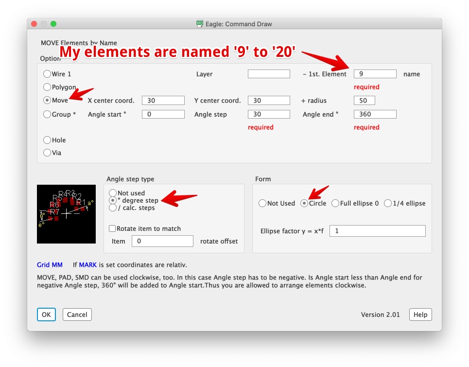
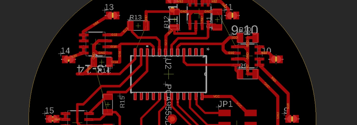
- The result

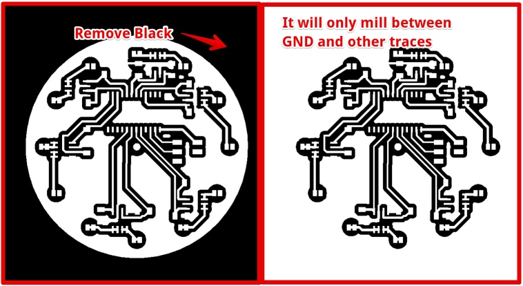
I wanted to have a common GND, so all unused copper-traces are GND and they are all connected.
The goal is to use all remaining copper as GND. To:
- Have enough current to the heatwires
- Go around the components with the GND trace, fix 3 Airwires
The BOM (Bill of Materials):
- 6 x dual MOSFET = DMG9926USD
- 1 x 6 pin HEADER = CONN_03X2-PINHEAD-SMD
- 2 x 6pin header connector (female)
- 10cm flatcable for 6 pin header
- 12 x 5K Resistor R1206FAB
- 1 x I2C chip = PCA9555D
- 12x 0,6 mm PCB Rivets
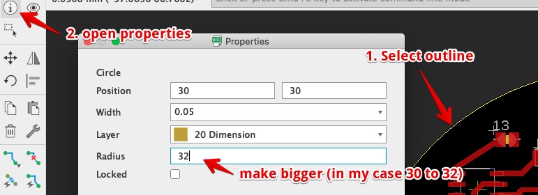
Steps to make all copper GND in Eagle:
Make the Dimensions bigger (the rats-nest will keep its margins)
Enter (or select) Polygon command, use these settings:

draw (on Top layer) around the new outline (the tool is crazy you don’t have to be precise), double click to close the Polygon.
Enter ‘GND’ in Signal Name pop-up

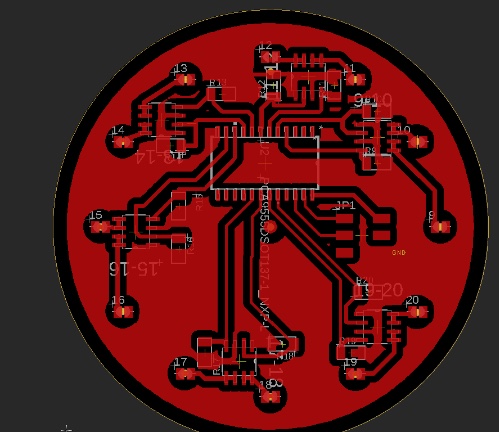
If all went well you will see the closed Polygon 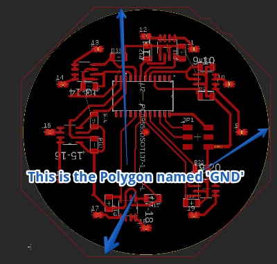
Now enter (or click) the Rats-nest command
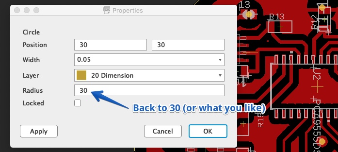
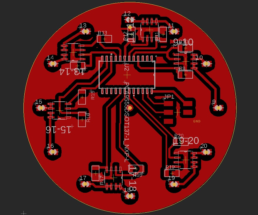
Now set the size of the Dimensions back :
The result from eagle
Now export PNG (select top layer > Monochrome > 500DPI)
Open in Photoshop and remove the black background:
Milling the board
Since working from home I check my PCB’s via the http://mods.cba.mit.edu/, before asking my Lab manager to mill it.
But this week the output is really strange. It took me some time, but it behaves like this for all PNG’s (also Neil’s example PCB’s) in Brave.
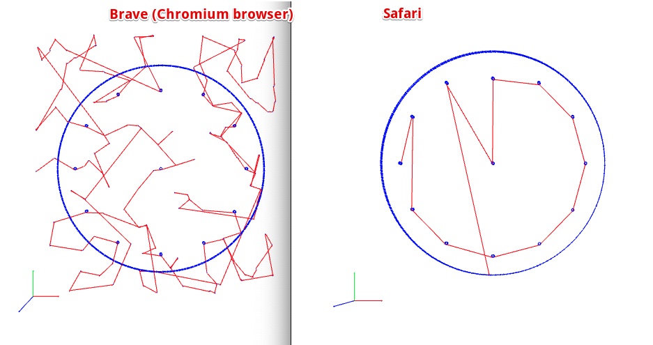
I created an Issue in the Issue tracker of Class 2020
The issue was replied by several persons, Henk mentioned Brave acted like this on Brave within Linux too. I Tried in Chrome, It worked.
Henk Milled the board for me, he used .003 inch dept for the traces (used to be .004 inch). The result was perfect. The only problem was the one drill hole on the wrong spot: 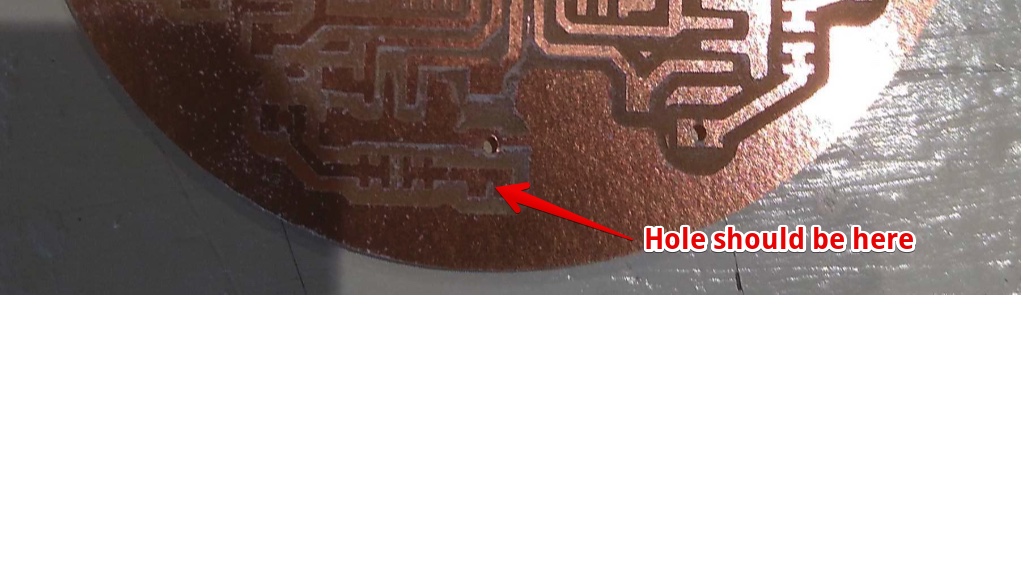
It was in my Design, and since it is on the ‘back’ it was hard to find when checking my designs: 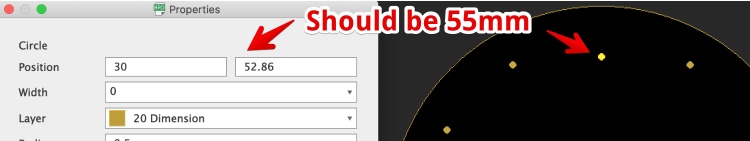
I used a 1 mm drill and managed to get a hole at the right spot without breaking the drill: 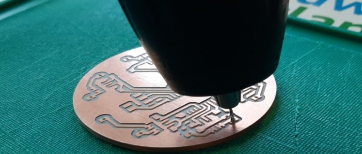
Fire up my I2C board
The I2C chip delivery was delayed, so I could not test this board this week. But I will start next week by looking at this tutorial Good explanation how to connect I2C chip to Arduino
In week 15 the PCA9555D arrived. I soldered the components on the board. Connected the board to a NodeMCU with I2C scanner code on it.
I2C port not found ;-(
The Node Did not show an address in the serial Monitor. I used this schematic: 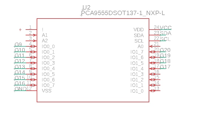
Since it is not working, I looked for others schematics. I found this: 
Problems understanding the datasheet
The biggest difference with my schematic is:
- connected INT
- connected A0,A1 and A2.
So I connected the A0, A1 and A2 to de GND with a wire, and changed it in EAGLE. 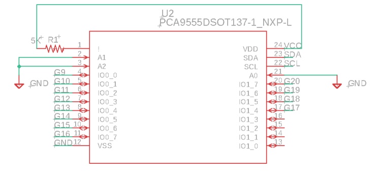
No it is similar to the example in the PCA datasheet 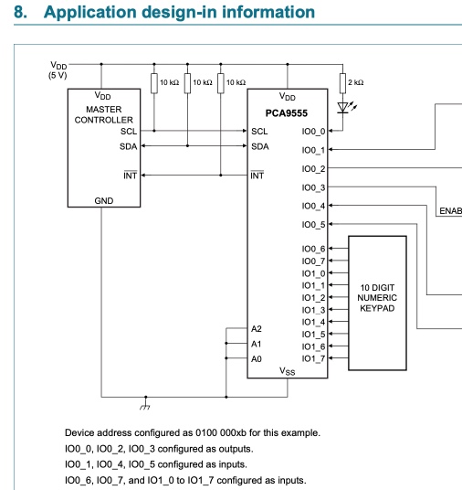
Problem solved!
While searching for a day for solutions I Redraw the whole schematics on paper and checked the wiring. I Checked again with the multimeter. But now on the legs of the I2C chip.
There was no connection between trace and pin of my SLC: 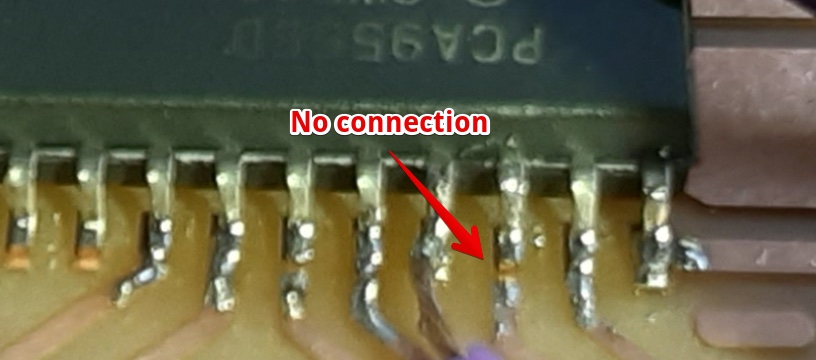
The Address was now found!!! 
I still did not know what the INT was doing. The information in the datasheet was really only telling met it is ‘input INT’.
With the kind help of Florent (my Fellow Fab Academy student). We found the answer in another datasheet: http://www.ti.com/lit/ds/symlink/pca9555.pdf?&ts=1589640038752
Harm  4:29 PM
thank you! But I don't see why I would need this. I found this, but I don't see how
I should use it "The open-drain interrupt output (INT) is activated when one of the
port pins changes state and the pin is configured as an input. The interrupt is
de-activated when the input returns to its previous state or the Input Port register is read"


Florent Lemaire  4:30 PM
in i2c you just send data, to receive signal, you have to listen of send request
4:30
*or send
So INT is only useful if I configure one as of the ports of the I2C as an input. But I won’t. I just leave INT not connected.
Hero Shot. The working Heatpath, with a piece of paper and thermocromatic ink on it (47C Red screen Ink)
- Embed video
Final files & Lessons learned:
Final Files
- PCB - Heatpath I2C Eagle Board file
- PCB - Heatpath I2C Eagle schematics file
- PCB - Outline PNG file
- PCB - Traces PNG file
- Arduino Code - I2C scanner
- Arduino Code - Video: Power Heatwires one by one
Lessons learned
- Even if the soldering looks nice, it can be not connected. Always check if the soldering is right. By measuring the resistance between leg and copper trace.
- Always look for ‘Typical Application’ in the datasheet.
- There are more datasheets for the same component, some datasheets are better