11 - Output devices
The output of my project will be Thermochromatic paint/ink in a painting. But how to heat it?
Assignments
- individual: add an output device to a Microcontroller board you’ve designed, and program it to do something
- group: measure the power consumption of an output device
How can I use this in my final project?
- In the final project will use Thermochromatic paint, I have to heat this. I want to create an output device heatpath and connect 12 wires to a Microcontroller.
Steps
- Group Assignment
- What would the output look like?
- How to discolor paint?
- How can I change the colors of the tomato?
- What is the best material to use Joule heating with?
- How can I get enough Current trough the wires?
- Design a PCB with MOSFETS
- Create a board with the DMG9926USD SMD MOSFET’s
- Make the output PCB
- Test the PCB
- How to spread the heat more evenly (not showing the sharp line behind the paint)?
- Apply paint on paper
- Which heat conductive material can I use?
- How can I drive the 36 Mosfets with one Microcontroller?
- HERO TIME - The end result
- How can I control which led (and thus heat-wire) will go on/off?
- PWM tests
- Files & Final conclusion for this week
Group Assignment
- group: measure the power consumption of an output device
since the Covid-19 restrictions are still in place, we in a video conference. I prepaired and tested measuring voltage with an Arduino. But we did not have 1ohm resistors. We had 4 multimeters among us, so we took the power cord from the output and put the Multimeter in series to measured the Current. From the current we where able to calculate the power. P = U x I (Power in Watt = Voltage x Current )
Read all about our group assignment measuring the power consumption of output devices
What would the output look like?
I want to display wind predictions in a painting. In the artist impression below you see 3 days of predictions:

Every tomato stands for a day of wind predictions for my kitesurfing-spot (Zandvoort).
- Left tomato is today
- Middle is tomorrow
- Right is day after tomorrow
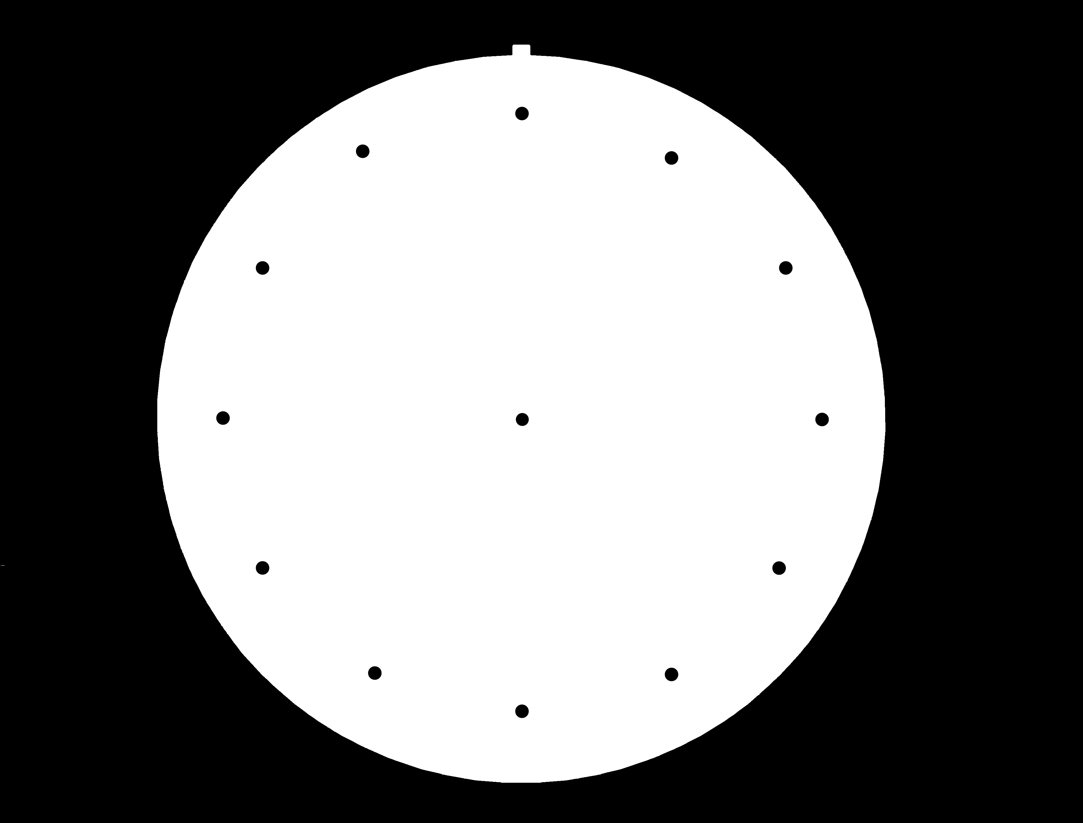
I use a hourly prediction models to have accurate wind predictions. So I need to display the predictions for every hour on every day (during daylight):
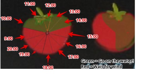 I device the tomato into 12 parts. To show predictions for the hours.
How to discolor paint?
During the weeks I have ran several test using Thermochromatic paints. https://www.sfxc.co.uk/collections/thermochromic-paint
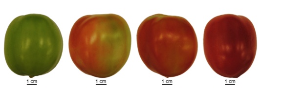 from http://tea.solgenomics.net/anatomy_viewer/microscopy/slm82_fruit
How can I change the colors of the tomato?
I use Thermochromatic paint. If I heat it, it will discolor. Read all about this in my final project. There are a lot ways to heat something. But when looking at a way to heat using a Microcontroller and heat tiny parts I don’t list heating by fuels. The electrical ways to heat something are:
- Induction heating: Shaking the molecules by electromagnetic field.
- Examples: Induction cooking
- How it works: Shaking the molecules of a ferromagnetic substance by an electromagnetic field.
- Can I use it:
- no, my paint is not ferromagnetic
- no, the field could heat up the electronic parts in my project
- Using IR (light):
- Examples: I looked into this. But I need a very specific part of my object (paint) to be heated. The paint is just 50 mm across and I need to separate in 12 hours. To really bundle IR warmth looks impossible. So I dropped this Infrared to heat up the paint.
- Using Microwaves:
- Since it are waves, it will be hard to constrain the waves to a tiny part of my tomato
- Joule heating: Sending current trough an electric resistive material produces heat
- Examples: Hot Wire foam cutter, Toaster, Iron, Hair dryer, Electric tabletop hotplate
What is the best material to use Joule heating with?
- Since I’ve seen this wire on the Hot Wire Foam cutter in the Maker Lab (at my University). I asked Cees (the Lab Boss) a piece of spare Nichrome Wire and did some test (see Final project.
Past weeks I looked at projects from other Fab Academy students creating heat elements for Thermochromatic paints. They all tried creating heat-paths using PCB’s. The problems they found are:
- The PCB burns when you make a little mistake (F1 PCB is rated for 120 C, NiChrome can stand 1400 C)
- Copper is very conductive (100 times more than Nichrome), so they need a lot of length to create a heating path
While doing research I found another reason to use NiChrome
- When heated NiChrome creates an outer layer of oxide, this will protect the wire. Where other materials will loose Oxide when heated, so copper will fall apart after some time.
How can I get enough Current trough the wires?
I tested with the Power supply from the FabLab and a 0.17 mm NiChrome wire.
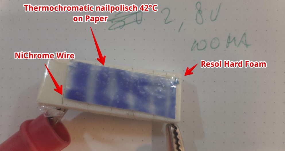
This test shows a piece of NiChrome and an thermal Insulator, I don’t want the wires to be visible. So I need to heat up not only the paint behind. But an entire part (1/12th) of a tomato.
I see two options to power high current
- Relays
- MOSFET
I went for MOSFETS since 36 relays will make noise.
testing Output with MOSFET’s - TEST BREADBOARD
I had IRLZ34N trough-hole mosfets and did a test:
- if I can open/close them using the 3.3 V logic level from nodeMCU
- They get hot/burned
- If I can adjust the current to control the heat
This is my schematic: 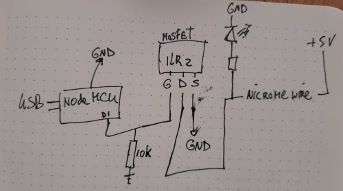
- I added a LED to see of the MOsfet was on
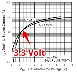
Can I open/Close it? According to the IRLZ34N datasheet the MOSFET does not open completely with the 3.3V
At one time i connected 7 heatwires (4cm long) To one mosfet, it got warm. But when I connected the mosfet to the D1 output of a NodeMCU it was not warm anymore. My assumption is the MOSFET gate was not connected and maybe half open. I read somewhere A half open mosfet will get hotter.
If I can adjust the current to control the heat. I tried to doe Pulse With modulation. I tried things, first 1 second off and 0,5 on. But you could see the paint pulsating. So I ended with this code:
void setup() {

  pinMode(D1, OUTPUT);
}

void loop() {
  digitalWrite(D1, HIGH); // open the MOSFET for 0,02 seconds
  delay(20);

  digitalWrite(D1, LOW);
  delay(80); // CLose (no current) the MOSFET for 0,08 second
}
There is something in the datasheet about the the open en closing time of a MOSFET. I could find what an ideal frequency would be to keep it on the save side.
Design a PCB with MOSFETS
Do I need to put a pull-down resistor to (gate) the circuit?
While playing with the breadboard setup I noticed the wires heated up rapidly and the paint produced smoke. This seems to be the case when the MOsfets gate was not connected. I have to see if I need to put a resistor between gate and ground to always keep the gate low (unless it should be high). To prevent in between states and full ON.
This exceptional explanation by BaldEngineer.com Explains the pull-down resistor:
Keep in mind, when connecting a transistor to a Microcontroller, until the pin switches to an output, the transistor’s gate floats.
In my case this is not acceptable, ‘floating’ would cause a fire. So I have to add a Resistor to pull-down.
What value of pull-down resister do I need?
It looks like the MOsfet gate is like a ‘capacitor’. So adding a resistor will act as an RC and will interfere with specific frequencies. Arduino forum suggests to take a low resistor (470 ohm) in these cases. I can Draw MAX 40mA per pin the Output, So if i use a 470 omh the draw would be 3.3V/470ohm = 70mA TO MUTCH!
So I picked a 5K resistor, this will draw 3.3v/5000om = 7mA
The pullup resister in a Arduino is 10-20K. So I think I picked a oke value.
!! TODO: Make sure the Resistor together with the capacity of the Mosfet is not blocking the PWN. Calculate what frequency this RC will block: https://en.wikipedia.org/wiki/RC_time_constant
Create a board with the DMG9926USD SMD MOSFET’s
I can’t find the footprint/component for the DMG9926USD. So I looked for an SOT
I can’t find an component representing the wires. So I tried to change an component into a wire. But it is very hard to change https://forums.autodesk.com/t5/eagle-forum/eagle-8-4-2-how-to-edit-existing-component/td-p/7555434
I found a similar component. But the site seems to be broken https://app.ultralibrarian.com/details/520440BF-E6C6-11E9-B85E-0AD2C9526B44/ROHM-Semiconductor/SP8K2TB?ref=digikey
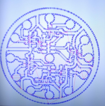
The schematics I designed
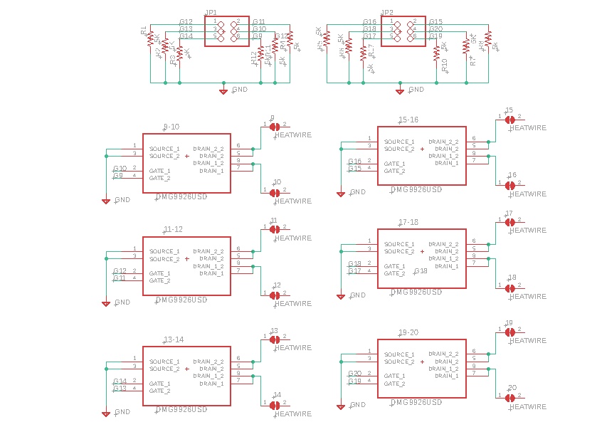
The settings to cutout the seatings for the wires:
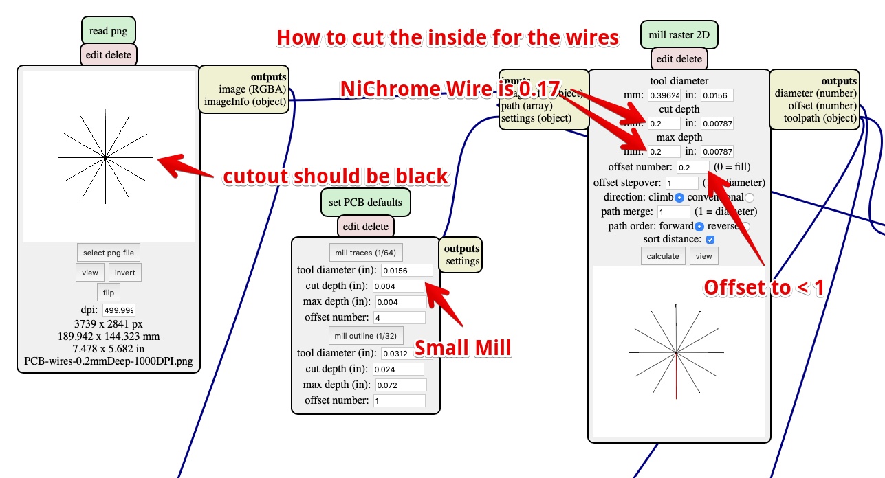
Make the output PCB
Since the Corona lock-down, Henk was so kind to mill the board for me. But while on the job, he contacted me about a strange hole outside of the PCB: 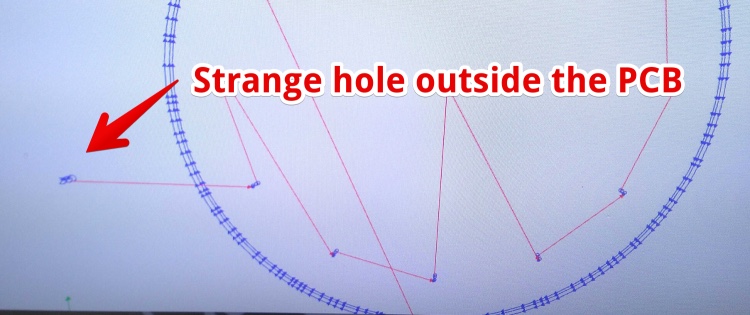
It was a lost pixel in the PNG file. I removed it in Photoshop and it a new file to Henk:
 |  |
Henk gave me a beautifully board: 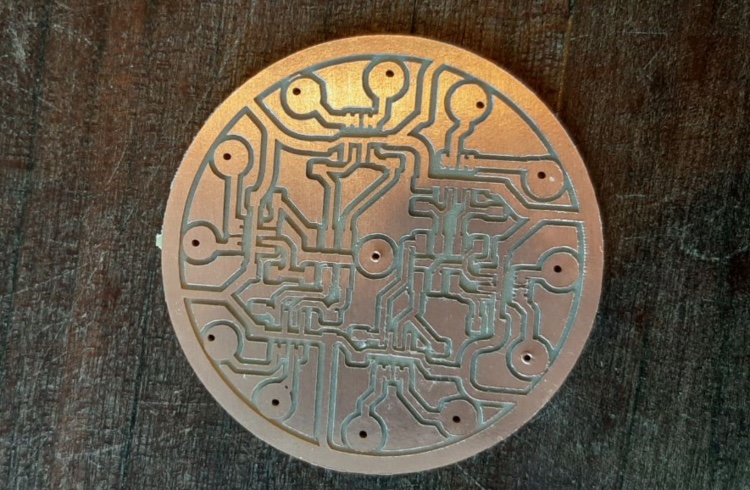
To seat the wires in a straight line (NiChrome is really stiff and always ‘curly’) I used a dremel handmill: 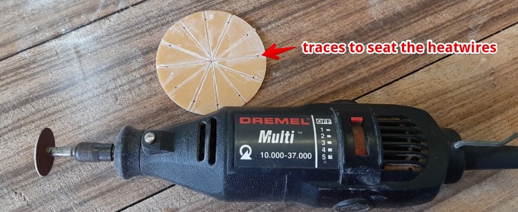
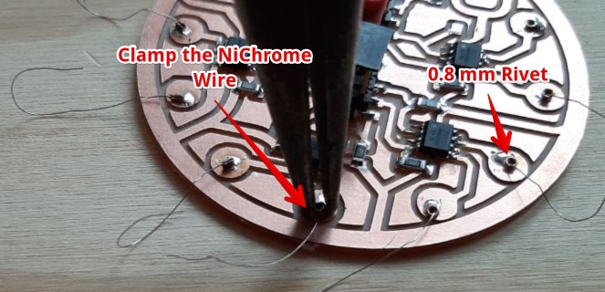
I soldered the components on it and put all the 12 NiChrome wires through the central whole: 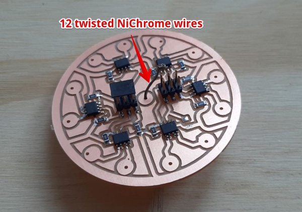
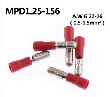
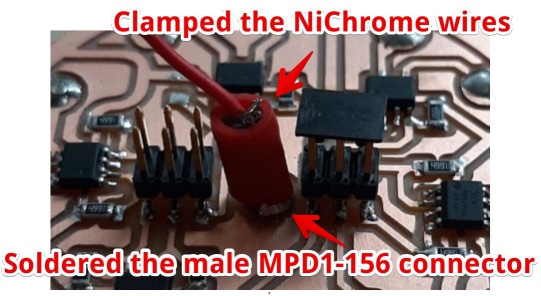
I clamped the wires (you can’t solder NiChrome) using a MPD1-156 connector and soldered the connector to the Copper path to keep everything stable:
 |  |
Attach the end of the wires:
- Put the 0.8 rivets in the 1.0 holes,
- Pull the wires a bit
- Squeeze the Rivets to clamp the wires
Soldered the rivets to hold rivet with wire in place: 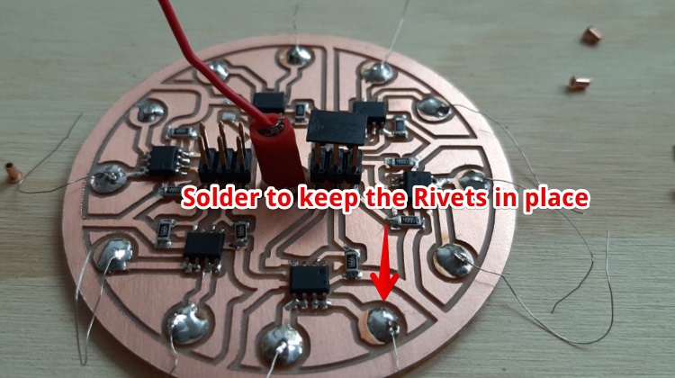
Test the PCB
To see if the NiChrome wires get Hot i had to create a piece with Thermo ink. So I made a piece with I Applied the 47°C Red Thermochromatic screen printing ink ink from SFXC. And used some scotch to stick it (more or less) for a quick test.
I plugged in the power to the MOsfets, but did not put any voltage on the gates. Smoke came from the paper and I pulled out the power supply:
.
The result was a piece of my test paper was burned a bit: 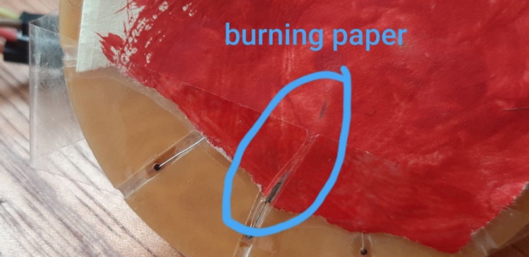
I looked at the board and found out I forgot two pull down resistors: 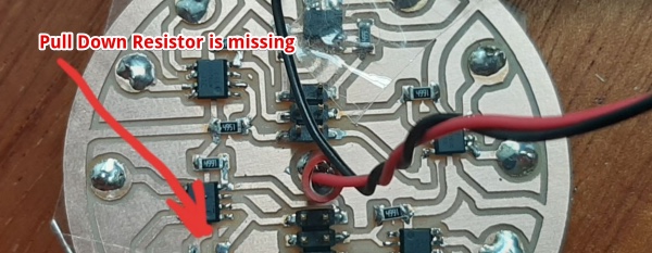 But Since missing TWO resistors and Only one wire getting hot it was surprising. So it is pretty random if a ‘floating’ input will cause it to go High. So I used the 12 pull-downs not for nothing (this was explained by Neil in his lecture about MOSFETS).
How to spread the heat more evenly (not showing the sharp line behind the paint)?
I wanted to spread the heat and flatten the heat-path. I used Epoxy resin to even it out.
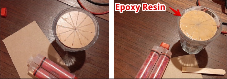
I used the 31°C two color Thermochromatic (nail polish) dye from HALI and mixed this with the screen ink binder that came with the screen ink from SFXC.
This is the result of powering 5 NiChrome wires: 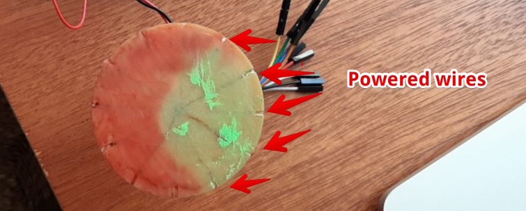
It works, but looks really terrible, this must be improved:
- I did not mix it properly, you can see some not binded dye on top
- I used the brown’ish’ background of the PCB, I should first make it white
- The Epoxy is not flat, I should sand it or press the epoxy (while wet) to get it flat
- I want some heat conductive material to save power and spread the heat more evenly
Apply paint on paper
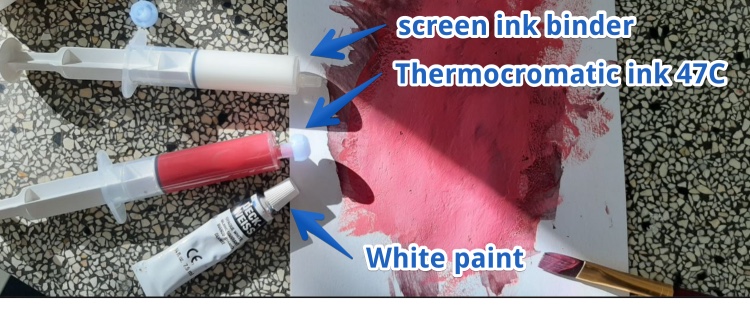 First I applied a green layer normal water paint. Then I did several layers, on the top layer i mixed white (acrylic paint) with the thermo screen ink.
Which heat conductive material can I use?
I want to spread the heat, and I don’t want the lines (wires) to be very visible in the painting. So I have to find a material on top of the wires that. This material should:
- Even it out, the paper has to stick to it
- Spread heat
- Don’t conduct current
Since Epoxy has a poor Thermal conductivity (0.15–0.25 W/mK), compared to copper (380W/mK). But copper will conduct the electricity in the wire.
I looked for an material to mix with the epoxy. The page on Wikipedia showed a table.
I ordered Manganese (MN). But when this Arrived I found out I was made a big mistake. Where I thought the value for MN is 7810 W/mK. It was actually 7,810 W/mK. 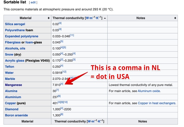
In the Netherlands we use a COMMA as a decimal separator where other countries use a DOT:  (image from WikiPedia)
If anyone needs 500 grams of Manganese powder, just let me know!
Next steps towards the heat-spreading
- Grind copper to dust
- Mix this with epoxy resin and test if it is not conducting current but spreads heat better
- Don’t mill seatings for the NiChorme wires, it is better is they stay on top since the PCB board
- Find Boron Arsenide powder? (4x better heat conductivity than copper)
How can I drive the 36 Mosfets with one Microcontroller?
- Using a Microcontroller with a minimum of 36 GPIO’s lot of outputs
- Using a Multiplexer
- Using multiple microcontrollers
I ordered a trough-hole multiplexer IC some weeks ago (Corona time). So I tried to get this running, and succeded to drive 4 leds (see )
with the help of this post I was able to drive 8 LED’s https://makersportal.com/blog/2019/3/12/controlling-leds-with-multiplexer-and-arduino
int S0 = 2; //D4
int S1 = 4; //D2
int S2 = 5; //D1

int outputs[4] = {S0, S1, S2};


void setup() {
  delay (100);
  Serial.begin(9600);
  for (int i = 0; i < 4; i++) {
    pinMode(outputs[i], OUTPUT); // output selection for LED control

  }

}

void loop() {
  // looping through all 8 LEDs
  for (int j=0;j<8;j++){
    // turn on LEDs based on bit conversion
    for(int i=0;i<3;i++){
      digitalWrite(outputs[i],bitRead(j,i));
    }
    delay(100); // delay .1 sec
  }
}
HERO TIME - The end result
How can I control which led (and thus heat-wire) will go on/off?
The test above uses ` digitalWrite(outputs[i],bitRead(j,i)); ` to create the values for the inputs of the multiplexer. bitRead (j.i) will be: 0 0 0, for the first led 0 0 1, for the next led
This is a binary counting table and I’m almost sure. So if I send a the number of the leg and convert this to binary.
I attached the heatpath to the power and to the outputs. The heatpath showed 6 warm spots. Exactly where the MOSFETS are on the back! I pulled the power out:
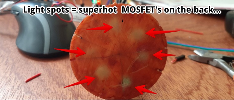
Then I found the probably cause. I SWITCHED VCC and GND: 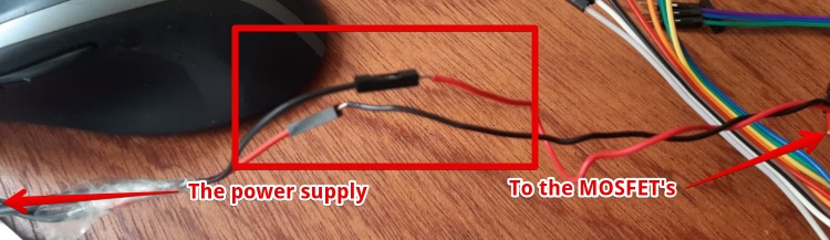
I changed polarity back again and hoped it was not dead. Still none of the heatwires got warm.
Turned out I forgot to connect the GND from the power supply tot the GND of the NODE. and It works
Get the multiplexer send one by one the data one by one to the outputs (to the MOSFETS)
The code below is now able to address specific leds:
int S0 = 2; //D4
int S1 = 4; //D2
int S2 = 5; //D1

int pulse = 300;

int outputs[4] = {S0, S1, S2};//outputs TO the MUX
int input [8] {1, 1, 1, 1, 1, 1, 1, 1}; //INput for the MUX
int mux[4] = {D6, D7, D8};

void setup() {
  pinMode(outputs[0], OUTPUT);
  pinMode(outputs[1], OUTPUT);
  pinMode(outputs[2], OUTPUT);

  pinMode(D8, OUTPUT);
}

void loop() {
  for (int x = 0; x < 3 ; x++) {// ACTIVATE MUX 0 to MUX 2 one by ONE

    // addres all 8 outputs
    for (int j = 0; j < 8; j++) {

      // connect input ON or Off
      digitalWrite(mux[x], input[j]);

      // Adress all outputs and connect to the input
      for (int i = 0; i < 3; i++) {
        digitalWrite(outputs[i], bitRead(j, i));
      }
      delay(pulse);
    }

  }
}
I figured out what bitRead is doing:
- It will convert a number (decimal) and find the decimal numbers on a specific place.
bitRead(6, 1)will convert 6 to binary = ‘110’ and output the binary bit on position 1. The position starts with 0 and on the right, so bitRead(6,1) will return (the middle) 1
https://www.calculator.net/binary-calculator.html?d2bnumber1=8&calctype=d2b&x=79&y=27#decimal2binary
I want to visualize the output with the Arduino so I was able to follow the way it works. I added output using the serial Monitor from the Arduino and Added Serial.println on several places:
 // addres all 8 outputs
    for (int j = 0; j < 8; j++) {
        Serial.println("----");
      Serial.print("j: ");       Serial.println(j);

      // Set input ON or Off
      digitalWrite(mux[x], input[j]);
      delay(pulse);

      // Adress all outputs and connect to the input
      for (int i = 0; i < 3; i++) {
        digitalWrite(outputs[i], bitRead(j, i));
        Serial.print("Bitread: "); Serial.println(bitRead(j, i));
      }
The serial monitor showed the output and this is like expected
13:25:55.967 -> j: 0
13:25:55.967 -> Bitread: 0
13:25:56.003 -> Bitread: 0
13:25:56.003 -> Bitread: 0
13:25:56.040 -> ----
13:25:56.040 -> j: 1
13:25:56.040 -> Bitread: 1
13:25:56.040 -> Bitread: 0
13:25:56.077 -> Bitread: 0
13:25:56.077 -> ----
13:25:56.077 -> j: 2
13:25:56.077 -> Bitread: 0
13:25:56.112 -> Bitread: 1
13:25:56.112 -> Bitread: 0
13:25:56.112 -> ----
13:25:56.112 -> j: 3
13:25:56.147 -> Bitread: 1
13:25:56.147 -> Bitread: 1
13:25:56.147 -> Bitread: 0
13:25:56.182 -> ----
13:25:56.182 -> j: 4
13:25:56.182 -> Bitread: 0
13:25:56.182 -> Bitread: 0
13:25:56.217 -> Bitread: 1
13:25:56.217 -> ----
13:25:56.217 -> j: 5
13:25:56.217 -> Bitread: 1
13:25:56.255 -> Bitread: 0
13:25:56.255 -> Bitread: 1
13:25:56.255 -> ----
13:25:56.293 -> j: 6
13:25:56.293 -> Bitread: 0
13:25:56.293 -> Bitread: 1
13:25:56.293 -> Bitread: 1
13:25:56.330 -> ----
13:25:56.330 -> j: 7
13:25:56.330 -> Bitread: 1
13:25:56.330 -> Bitread: 1
13:25:56.364 -> Bitread: 1
This is exact like the 74HC4051 datasheet shows it: 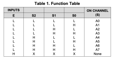
My plan is to use 2 multipliers with 12 outputs. But in this test I don’t see the Thermochromatic paint changing when i use a PWM of 40ms every When multiplying the signals to 3x8 (the mux is 8 outputs) But even if i only multiplex over 3 x 8 channels and set the PWN on 40ms, nothing is visible.
Find the right Multiplexer
- Looked for similar problems on the internet EG ‘Driving multiple outputs Arduino’
https://makersportal.com/blog/2019/3/12/controlling-leds-with-multiplexer-and-arduino is a nice start to get an idea of how a multiplier works.
- I’ve entered the part numbers, Farnell didn’t come up with the part. Digi-key did, so i sticked with Digikey
- I got a list of parts, all simulator to me. But i picked the one where we could order 1 and looked in the datasheet:
- Within the datascheet different types are available. It confused me it is called SO, SOIC or SOP. The major factor I was looking for was the distance between the legs. I have soldered 1.27 in previous weeks, so I don’t want to go smaller.
These are Package types I want to use: 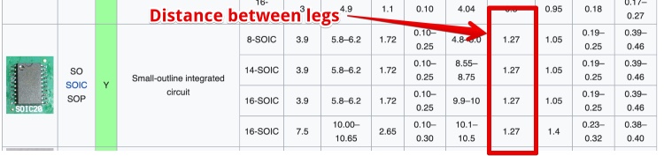
I found a nice overview of all the Package types available on this Wikipedia page
“NOTE: When ordering, use the entire part number. The suffix 96 denotes tape and reel.” Since i don’t need an entire reel I chose the “Cut Tape (CT) “ version. via https://www.digikey.nl/products/nl?keywords=CD74HC4067
I Chose the “CD74HC4067M96” from https://www.digikey.nl/product-detail/nl/texas-instruments/CD74HC4067M96/296-29408-1-ND/2741760
- Digitkey number: 296-29408-1-ND
- Number of components I need: 3
PWM tests
During week 8 and week 9 I tried to get an ESP-12 designed and created a board arround the ESP-12F. They both failed. During this week I designed a working ESP-12F board. This page explains how I made this working ESP-12F board
Goal: Test how long the pulse should be to get enough heat to change the color of the paint. Using my own microcontroller board.
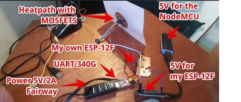
Setup: This is the setup to power my ESP-12 and power the Heatpath:
Code:
// int pulse = 30; //visible, but a clear line
// int pulse = 40; //visible, a thick line (no smoke)
//int pulse = 50; //very visible, quick respons
int pulse = 100; //very visible, quick respons

void setup() {
  pinMode(4, OUTPUT);
  pinMode(5, OUTPUT);
}

void loop() {
  digitalWrite(4, 1); // set the LED on GPIO 4 ON
  delay (pulse);
  digitalWrite(4, 0); // set the LED on GPIO 4 OFF
  delay (100);

  digitalWrite(5, 1); // set the LED on GPIO 5 ON
  delay (pulse);
  digitalWrite(5, 0); // set the LED on GPIO 5 OFF
 delay (100);

}
- Result: Using the Fairway 5V/2A power supply and a 200ms low:
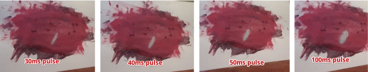
Only when I use a PWM of 320 low and 40ms high, the result for the 47C red is oke (you see the color changing). So multiplexing one output to 36 wires will never work…
In the global evaluation Henk revered Neil to this output page. He again pointed to the possibility to use Charlieplexing. But now using a diode and not a LED. So I think it could be possible. I looked into Charlieplexing on WikiPedia again. I need 7 pins to get 42 outputs. So it is Do-able with a normal Microcontroller. Next board: ESP-12 with charlieplexing!
Files & Final conclusion for this week
Files I made
- the Eagle board file
- the Eagle schematics file
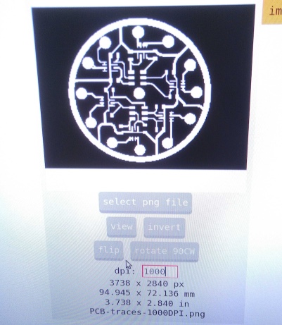
- Outline PNG
- Traces PNG
- Code to trigger all Mux outputs one by one
- Code making PWM to heat the output wires
Final conclusion for this week
- using green paint, and a thick layer of Thermochromatic 47C red does not show the green under it
- Multiplexing does not work, the Pulse is not big enough. Or the power supply is not strong enough?
- It is a lot easyer to program a microcontroller than to controll a multiplexer, next I will use multiple microcontrollers to expand my output (Luc told me so!)
Biggest Mistakes and lessons this week
- Working with loose wires and breadboard is not the way forward, for the Multiplexer I have to make a PCB
- I need an other power supply to heat the wires
- Lesson: first test the output with an easy entry board (like NodeMCU) before testing with my own board
Wat I really liked
- My ESP-12F PCB design worked
- My Output PCB is nice
My concerns
- The paint is not a red as it should be, finding the right mix is hard
- The green paint is not visible if i first put a layer of green