10 - Project masterpiece plan
This week is al about planning and plans. It helps me to get my plan straight, find the gaps and missing links. Find out if this is really enough to display my new Fabacademy skills.
Assignments
- individual :Propose a detailed final project masterpiece plan
- group : No Group assignment this week
How can I use this in my final project?
- This is the scope and planning of my final project
Mu final project proposal
- 1. introduction to my final project
- 3. What kind of additive process will I use
- 4. What subtractive fabrication processes will I use
- 5. What Electronics will I design and produce
- 6. Embedded microcontroller interfacing and programming,
- 7. System integration and packaging
- 8. Overview of all the parts of my project
- 9. List of electrical components
- 10. Similar projects
- Final conclusion for this week
1. introduction to my final project
I want to display wind predictions in a painting. In the artist impression below you see 3 days of predictions:
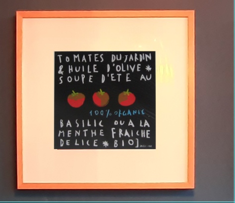
Every tomato stands for a day of wind predictions for my kitesurfing-spot (Zandvoort).
- Left tomato is today
- Middle is tomorrow
- Right is day after tomorrow
I use a hourly prediction models to have accurate wind predictions. So I need to display the predictions for every hour on every day (during daylight):
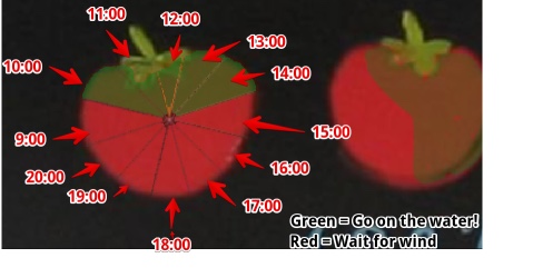 I device the tomato into 12 parts. To show predictions for the hours.
2. Materials needed
- Thermo-chromatic paint
- Electrical components
- Paper (for the painting)
- White cardboard (for the passepartout)
- Soft board, for the back of the paper
- Nichrome wire ( 0,17 mm Wire: Nichrome)
- Glass for the painting (Do I really need this?)
- NodeMCU/ESP-12F I hope I have time to create a board around a ESP-12, but my goal is to finish the project. I think about the spiral design and start with a ready made NodeMCU.
- Glass for photo frame?
- Cardboard behind frame To make the ‘passepartout’ I need thick white cardboard (1 mm x 500 x 500 mm)
- Epoxy to level the PCB with heat-paths
- Glue (?) to stick the heatwire-PCB to the painting
- Two power supplies (I can reuse old phone chargers)
- one 3.3 V to power the ESP module
- one 5V to power the heatwire-PCB and mosfets
2.1 What will I Make
- Reproduce a painting with parts of Thermochromatic paint
- The non thermo part could be printed/done with screen ink
- I thermo paint I hope to apply with screen technique, I know nothing about this…
- 3x PCB heatwire-PCB with electronics to heat the wires <- This is the masterpiece
- 1x PCB containing to multiply the single output from ESP to drive 36 MOsfets (maybe I can integrate this on the heatwire-PCB)
- The code to get data from the internet and convert this to 36 heat wires
- The Frame of the painting
- (MoSCoW) a custom made ESP12 board
2.1 How much will the materials cost?
- Paint: 20 pound including shipping SXS
- 3x PCB-heatwire (5 euro each?)
- PCB driving the heatwires (5 euro?)
- Photoframe (wood, paper cardbaord) (10 euro?)
- Node/Custom ESP-12 board (2 euro)
3. What kind of additive process will I use
- I’m going to create heat conductive epoxy composite material to spread the heat.
- I probably need to 3d print forms as a way to hold the epoxy resin.
4. What subtractive fabrication processes will I use
- Milling (Small Milling machine): PCB’s
- Milling (Big CNC): painting frame
- Laser cutter: cardboard back
- Laser cutter: Cardboard Passepartout
5. What Electronics will I design and produce
- PCB Heatpath with mosfets an Nichrome wires
- PCB IO multiplier
- PCB ESP-12F (maybe)
6. Embedded microcontroller interfacing and programming,
- ESP-12 code
- Connect to WiFi
- Convert weather data to hourly ‘heat’
- Controll power to heatwires (PWM?)
- API: mulitple options
- Find an existing API
- Create my own (partly done by me but uses screenscraping technology)
- controll 36 mosfets:
- Use A multiplexer (PWN is not possible?)
- Use a Microcontroller (I have to program this, so the board will be less compact)
- Use a shift register (I can)
IDEA: I can use one big MOSFET to do the PWN on the central power of the Wires and use a Shift register. In this way I cannot differ the heat per wire. Or can I?
7. System integration and packaging
It is a complete project. Including casing.
8. Overview of all the parts of my project
- Thermochromatic Painting (paint/print on paper)
- Frame (frame, glass, back, passepartout, clips to hold painting)
- Heatwire PCB (heatwire, MOSFETS, headers)
- Power supplies (2x)
- Microcontroller PCB
- IO multiplier PCB
9. List of electrical components
- MOSFETS
- Shift registers?
- ESP-12E/NodeMCU
- Nicrome Heat-wire
- Resistors
- NTC thermistors
- Headers
- Flatcable
- Power supply
- Connectors for power-supplies
10. Similar projects
I’m sure I’m not the fist person in the world thinking about displaying data with Thermochromatic paint. In past weeks I have been collecting examples and will list them all below to make sure I can learn from it
Previous Fab projects using thermo inks:
- Textiles and Thermoink - Anastasia Tsaparoglou - Fablab Spinderihallerne in Denmark. She tried u use it on textiles, but burned the heatpaths and never was successfully. In her final project she left it out. (she named it ‘photochromic’)
- Responsive Furniture - Anna Fusté Lleixà - Fablab Barcelona . Used it in her Final project, to heat cabinets. Created an heatpath using a PCB. This is not an option in my project, there is no space to make long copper traces.
- Controlled PCB Copper Heatpath with a MOSFET - Francesca - Fablab Barcelona. She did not use PWM
Final conclusion for this week
- I’m on track when it comes to my final project
Biggest Mistakes and lessons this week
- I spend forever finding the proper footprint for my mosfets (I was working secretly on paint heating)
Wat I really liked
- My PCB design
My concerns
- Will the painting be as good as we have now
- Can I display different wind strengths?
- Will De Waag be open in June?