 Erwin Kooi
09 - Machine design
This week(s) will be a collaboration with three other student to design a machine. What machine? Doesn’t matter much.
-
Group assignment:
- Design a machine that includes mechanism + actuation + automation
- Build the mechanical parts and operate it manually.
- Actuate and automate your machine.
- Document the group project
-
Individual assignment:
- Document your individual contribution.
- I know how to create individual parts (laser cutting, mechanics, electronics).
- Combining to a working prototype
- Organizing work in a group
- The Arduino IDE has some quirks when it comes to
#defineand calculations. These were solved by specifying the calculation in the comment and add the pre-calculated value as number in the#definestatement - Using other people’s code (Arduino libraries) can lead to ‘interesting’ conflicts
The group page with the description of the project can be found here.
The machine is split in four parts:
- torso
- arm
- hand/wrist
- electronics/code
I will focus on the electronics and the code and document my work on this page.
 The electronics will be built with a standard Arduino Uno, an Arduino Motor Shield (rev3), some motors and some limit switches.
The Arduino Motor shield uses a L298 ([datasheet](http://www.st.com/web/en/catalog/sense_power/FM142/CL851/SC1790/SS1555/PF63147)) dual full-bridge driver made by STMicroelectronics. With this motor driver you can control DC motors, stepper motors, relays, and solenoids. It comes with two separate channels, called A and B, that you can use to drive 2 DC motors, or 1 stepper motor when combined.
The electronics will be built with a standard Arduino Uno, an Arduino Motor Shield (rev3), some motors and some limit switches.
The Arduino Motor shield uses a L298 ([datasheet](http://www.st.com/web/en/catalog/sense_power/FM142/CL851/SC1790/SS1555/PF63147)) dual full-bridge driver made by STMicroelectronics. With this motor driver you can control DC motors, stepper motors, relays, and solenoids. It comes with two separate channels, called A and B, that you can use to drive 2 DC motors, or 1 stepper motor when combined.
Please disregard the previous paragraph, as I switched to an Adafruit motor shield. This shield provides four DC motor drivers (or two stepper motor drivers). I migrated the code to the AFmotor library that accompanies the board.
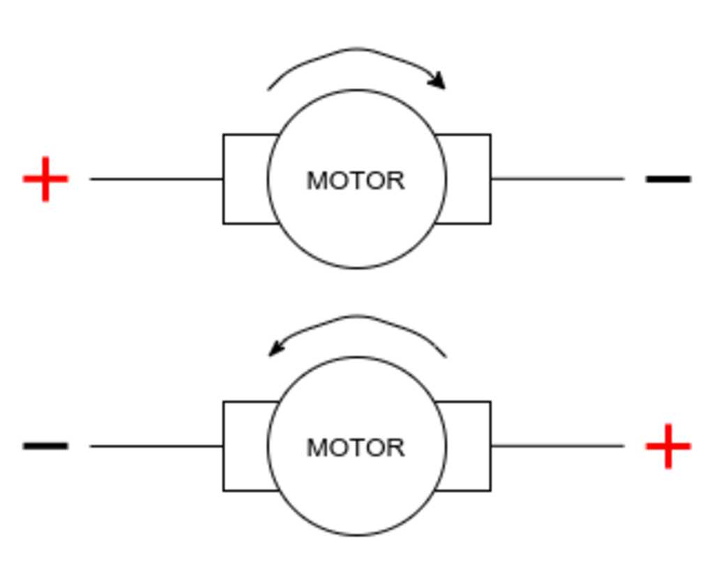
When driving DC motors, the polarity of the power will determine the direction of the spinning of the motor. A standard tool for controlling this polarity is by creating a H-bridge. So called for the configuration of the motor and the FETs in an H shape.
By switching two FETs, the voltage is sent through the motor in one way, making it spin in one direction. By switching on the two other FETs, the voltage is sent through the motor in the other way, making it spin in the other direction. Wiring the proper FETs together will give two control lines, one for turning left and one for turning right.
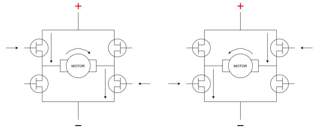
Switching on all FETs at the same time will result in a big short circuit.
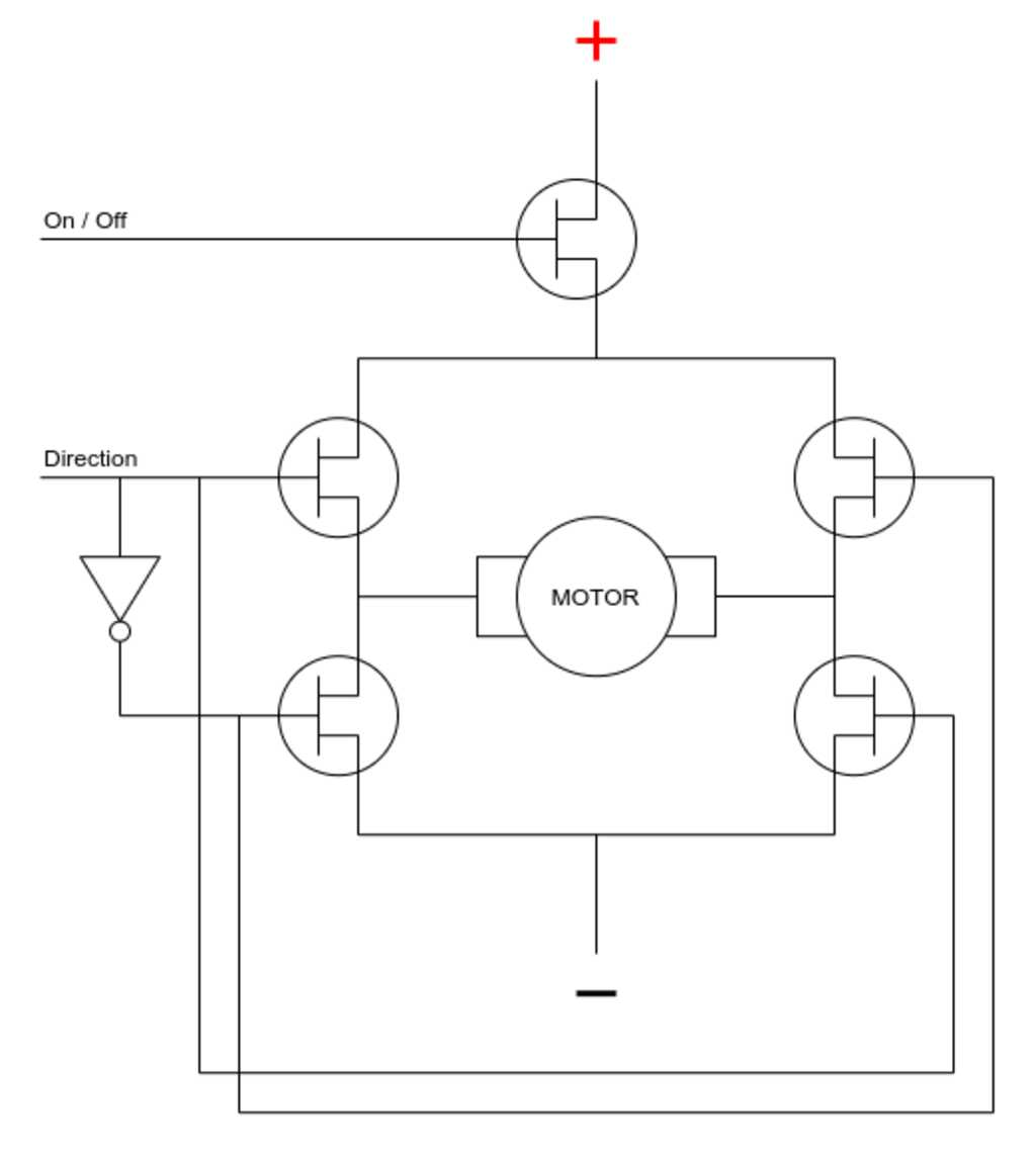 This can be prevented in software or in hardware, by connecting the proper FET inputs together and placing a logic inverter in line with one of the lines.
This will turn the motor always on, so a separate FET is required to power the motor on or off.
This will also result in two control signals, but will prevent accidental short circuits and result in a robuster design.
The arm will be controlled by a stepper motor and a belt. Why? Because we had one laying around and it allows us to work with multiple types of motors.
A stepper motor has two coils, in contrast with the DC motor which has only one coil.
The windings and magnets in a stepper are placed such that powering one of the coils will turn the rotor one step. Powering the other coil will turn the next step. Powering the first coil will then turn the next step, and so on.
Controlling a stepper means providing a timed signal to both coils.
WARNINGFor this project the used stepper will work, but it is something to keep in mind when designing future motor control boards.
Keep in mind is that the L298 driver does not have an easy way to set a current limit. This means that the current draw depends on the relationship between the inductance and resistance of the stepper motor. The specific stepper can therefor draw more current than the driver can provide, damaging the driver and running the motor hot.
The important part is to find which wires are connected to the same coil. This is quickly done by connecting two wires together and turning the shaft of the motor. If this is easy, the wires are from different coils. If this meets resistance from the motor, then the wires are connected to the same coil.
The connections are
| A+ | A- | B+ | B- | |
|---|---|---|---|---|
| color | red | blue | black | green |
The wrist will be controlled by a servo motor and a wire.
A servo motor has one coil and a feedback mechanism attached to the rotor. Providing a voltage level to the control connection will turn the rotor to a specific position and stay there. Providing another voltage level will turn the rotor to another specific position and stay there.
Controlling a servo means providing a voltage level, which can be generated by a PWM signal. The duty cycle of the PWM signal will determine the position of the rotor.
The connections are
| VCC | PWM | GND | |
|---|---|---|---|
| color | red | orange | brown |
The correct position of the wrist will be determined by a switch in the wrist, touching the shoulder of the subject. This switch will be a basic on/off limit switch connected to the D4 digital input pin. (Please see below where this went wrong…)
A potentiometer will be used to specify how much attention (=number of pats) will be given. This potentiometer will be connected to the A5 analog input pin.
 ### Code design
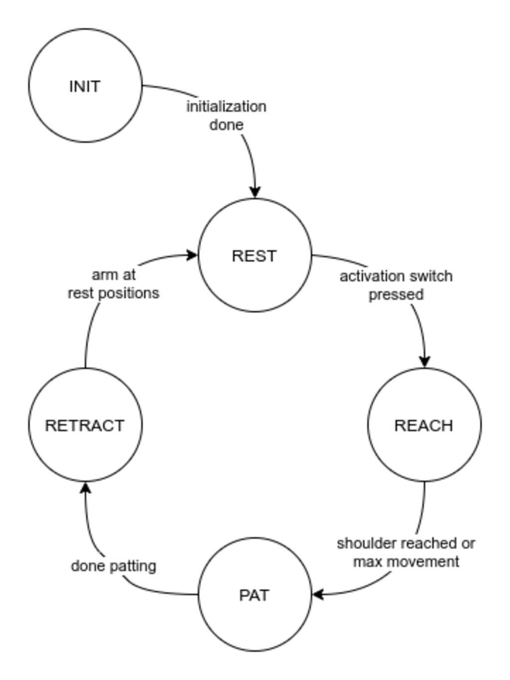
The machine has five distinct states (and off).
1. Initialization
2. Waiting for activation
3. Reaching for a shoulder
4. Patting the shoulder
5. Retracting from the shoulder
### Code design
The machine has five distinct states (and off).
1. Initialization
2. Waiting for activation
3. Reaching for a shoulder
4. Patting the shoulder
5. Retracting from the shoulder
After initialization, the states follow each other and loop around to 2.
The states will be used in a state machine that is programmed in the software. A switch statement is perfect for state machines.
Important reminder, close each case: with a break; statement or the case will never resolve.
Adding a default: case will make sure that whatever state the system is in, it will revert to a defined state.
switch (SystemState) {
  case STATE_REST:
  case STATE_REACH:
  case STATE_PAT:
  case STATE_RETRACT:
  default:
}
A few things of interest happen at the initialization phase.
The code uses the AccelStepper library for controlling the stepper motor. This library is more optimized than the default Arduino stepper library and offers acceleration and deceleration functions. Though these are not used in this project. In hindsight, the regular Arduino Stepper library would have sufficed.
The code uses the default Arduino Servo library for controlling the servo motor.
The stepper motor has 200 steps per revolution. The gear on the stepper has 21 teeth, the gear on the elbow has 60 teeth. This results in a gear ratio of 60/21 and therefor 571.5 steps are required for a full rotation. Since the elbow will move 180 degrees max, this means 286 steps will move the arm to its endpoint.
The potentiometer is placed between the 3V3 and GND. This means that the full reading of the potentiometer is 664. Since we want to have 4 levels of attention (0 to 3), the numbing factor will be 664/3 = 221.
In the rest state, the system will wait till the activation switch is pressed. While waiting, the potentiometer is read and if a different value is entered, it is sent to the serial port. When the activation switch is pressed, a reading of the potentiometer is done and stored in the AttentionLevel variable.
In the reach state, the system will move the stepper motor till the limit switch is pressed or the end of the arc is reached. The current position and end position are sent to the serial port.
In the pat stage, the system will move the servo to raise and lower the wrist. This will result in one pat.
Depending on the AttentionLevel variable, this is done a number of times.
In the retract stage, the system will move the stepper motor till the arm is back at its original position. The current position and end position are sent to the serial port.
The code for the pat-o-matic can be found here.
This was a very hectic week. My dayjob was very demanding (finishing an European tender) and a lot of things happened in my family.
- Creating the state machine was a breeze with the
switchstatement. - Especially when the team is working individually on parts of the machine, defining the interface how the various components will fit together is crucial.
- The motor shield can only drive one stepper (with two coils) and the driver is not current limited. This can cause the stepper to overheat and the driver to be damaged. For this project and the selected stepper it will not be a problem.
- The AccelStepper driver is somewhat finnicky on when to set what speed. If you call the .moveTo(position) function, it will reset the speed. So an explicit .setSpeed(speed) is required, otherwise the motor will turn with one step per second.
- Halfway the project I switched to the Adafruit shield and library, as this was able to drive a stepper motor (as demoed by Lucia). After days of debuggine, I found in the AFmotor.h library file on line 139 the definition
#define MOTORCLK 4. THis is required as output. It conflicts with the limit switch on pin 4 that I defined as input with pullup resistor for the limit switch… After moving it to pin 13, it worked like a charm!
- I would select another shield for driving the stepper. The CNC shield with Pololu drivers is specifically created for driving steppers and can regulate large currents.
- I have a tendency to take the lead in projects with a plan already in my mind. I deliberately did not do this in this project. This gave me an uncomfortable feeling, as I did not have the feeling that all parts of the projects would be covered and commitments were somewhat vague. Next time, I will try a somewhat more projectmanagement role.
- The stepper motor is drawing a lot (> 1 Ampere) of current. For this a Pololu stepper motor driver would have been better.
- The pulley on the stepper motor slips as it cannot provide enough torque for the elbow to move. A better solution is to use a strong servo for this joint too. The precision of a stepper motor is not really required, but the torque of a servo motor is.
- I would not enter group discussions on the scheduling of lab machines at 23h00…