 Erwin Kooi
02 - Computer-aided design
This week focusses on evaluating 2d and 3d design tools, their output and when to use them. I will also be making a choice of the tools to finish the final project.
The assignments for this week are:
- Model experimental objects/part of a possible final project in 2D and 3D software
- Shown how you did it with words/images/screenshots
- Include your original design files
- I already make some basic designs in FreeCAD and Inkscape.
- I want to experience a different kind of modeler. OpenSCAD and Blender are interesting options.
- When possible, I would like to try Fusion360. But this requires a Windows or Mac OS X operating system and my system runs Linux.
- Animation in FreeCAD using a sketch, referencing a body to it and using Python to modify a parameter can easlily crash the application. For most animations, the Exploded Assembly workbench provides basic tools.
- Fusion360 is available for Chromebooks (and thus Linux with a Chrome browser). I tried this, but the lagging of the mouse pointer makes this unusable.
The final project will likely be a puzzlebox with a number of panels that will hold the individual puzzles. These panels will be cut on the laser cutter and are therefor a good excercise in vector modeling.
Inkscape is a very versatile tool for working with vector-based drawings.
In this chapter I will design the front panel for one of the puzzles, so it is ready to be processed by a laser cutter.
The first thing we do, is to enable the grid. This will help us guide and place the various components of the front panel. LED’s, displays, switches, etc.
This is done in the “Grids” tab under the “File > Document Properties” menu. Selecting “New” will allow the coarseness of the grid. 1 mm is typically a good value to work with.
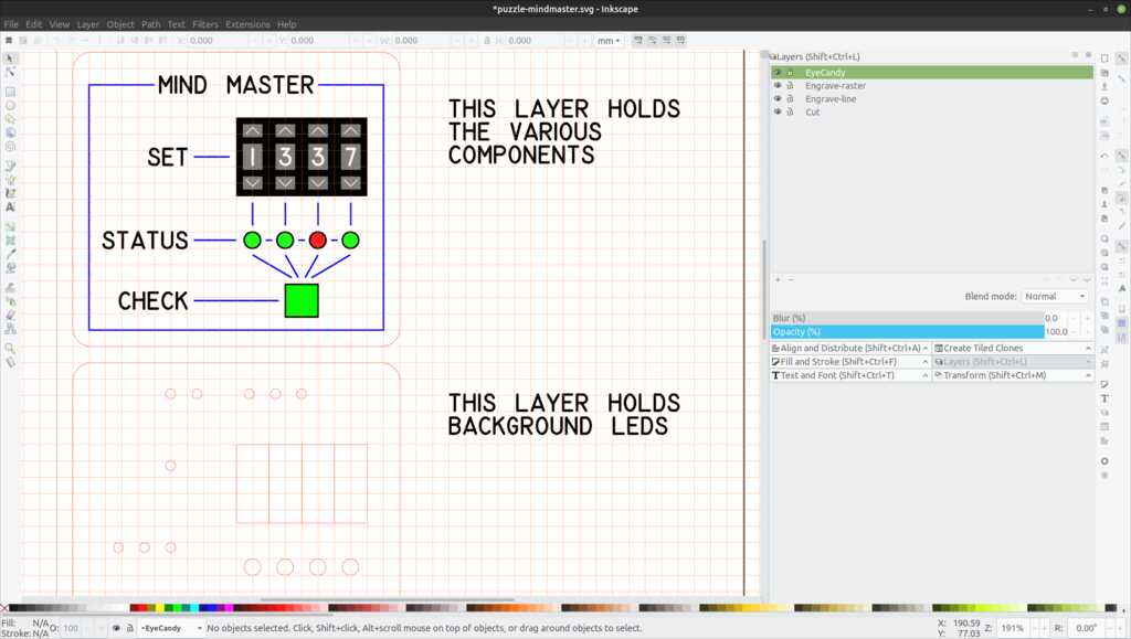
The second thing we do, is define layers to distinguish between the different techniques of laser cutting. A laser cutter can:
- cut
- engrave a line (vectors)
- engrave a raster (bitmap)
An additional layer for eye candy is added to show quickly why certain holes will be cut. For example to house a led or a switch.
By disabling / enabling a layer we can get a quick overview of how the various techniques fit together.
NOTE: This vector-based method also works for vinyl cutters.
The puzzle will be a kind of MasterMind. You set digits and the puzzle will tell you which digits are correct or placed wrong. This will be detailed further in the Final Project chapters.
The panel will consist of two layers. A top layer which holds the components and has engraved text. A bottom layer that will pass-through the components and holds LEDs for backlighting the engraved text.
Using milky white acrylic for the top layer and painting it before engraving, will give white characters that can be back-lit.
The eye candy is created using some colored squares and circles, as they will have no function in the fabrication process.
The Inkscape project file can be found here.
The empty Inkscape A4 template file with laser cutter layers can be found here.
For the final project I am building a puzzle box with various panels. This will require a frame to hold the panels (and if possible exchange panels easily). For this week’s assignment I will create an animation of an opening lid.
FreeCAD (version 0.19 forever beta) is a surprisingly powerful program. It uses a “traditional” way of CAD design (creating 3d bodies from a 2d sketch) and is very focussed on properly constraining the design, so there will be no surprises when physically producing it. This can be annoying (i just want to try some stuff), but if you train yourself to do it directly when creating the sketch, it becomes part or your regular workflow.
Every part of the model is parametric. The base parameters are defined in an internal FreeCAD spreadsheet.
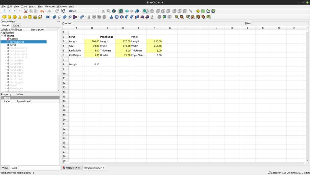
Dimensions are then calculated using this spreadsheet.
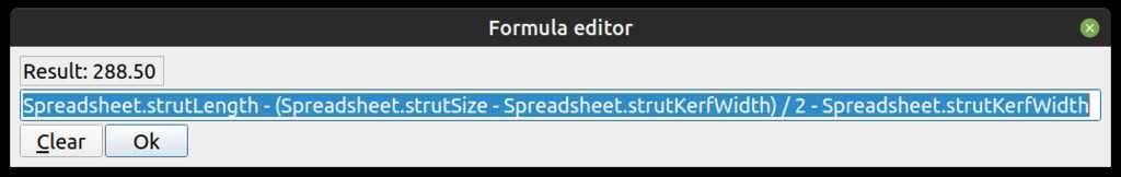
This makes it very easy to adjust the size of the frame, depending on the dimensions of selected materials later in the project.
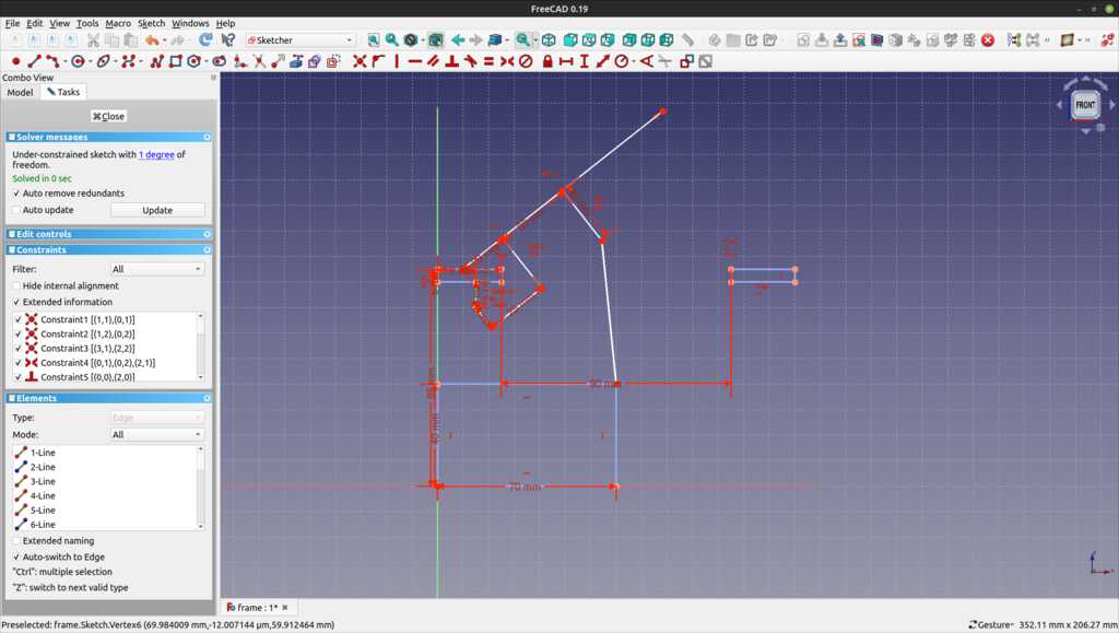
The hinge should not be visible, so it will not be clear from the start that this panel can be opened. We need a hinge mechanism that is strong but invisible. When we create a sketch in FreeCAD and leave it one degree of freedom, we can play with the sketch as if it is movable.

This shows the lid closed. The hinge is on the left side. The middle has a linear actuator that can extend, as we see in the picture below:
The lid will follow the path of this circle:
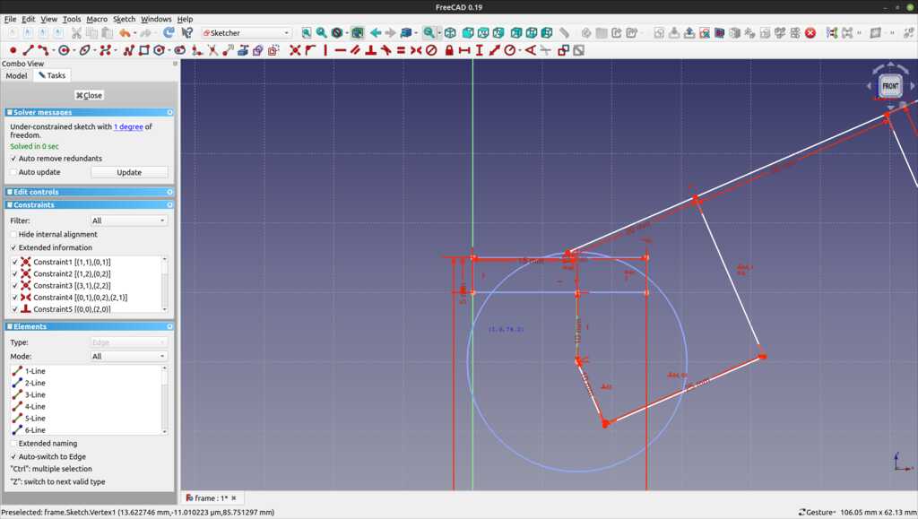
I tried attaching the modeled lid to this sketch and have some python code to modify the length constraint of the actuator. By incrementing / decrementing the value every second (using the PySIde.QTCore.timer component) this should give a nice continuous opening and closing of the lid in the final render. Unfortunately, I could not get this to work reliably.
The frame will be made of struts with slots in them to hold the panels.
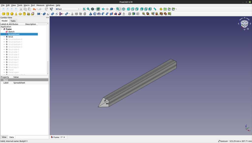
This strut is created by creating a sketch with a cross-section of the shown strut and then extruding it to the required length. On the sides without slots, a sketch is created to subtract the triangular form that will allow struts to be combined into a corner.
Twelve of these struts make up the total frame.
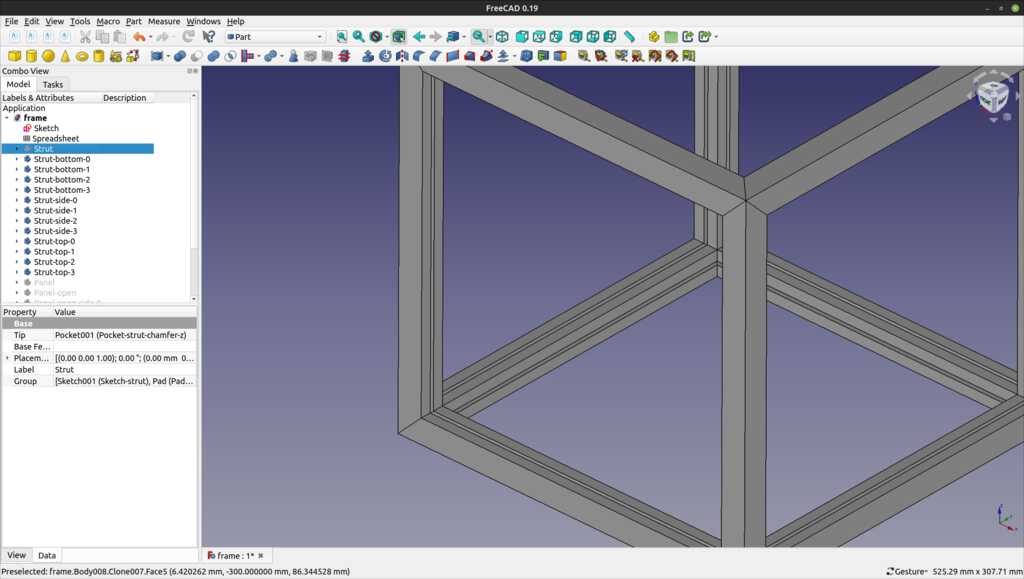
The struts are created by cloning the original strut and then rotating and translating them into the correct orientation. Cloning in FreeCAD is done with the “sheep” icon, named after the cloned sheep “Dolly”. 
The edge panels are also cloned by cloning one original panel and then rotating and translating them into the correct orientation. In this image (with one strut removed), you can see that they fit perfectly into the slots.
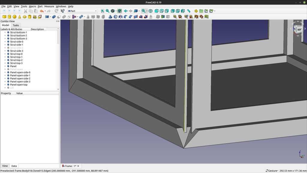
The edge panels are open, which will allow for a puzzle panel to be attached to it. This has two advantages:
- The puzzle panel will stick out a bit from this panel, adding some depth to the design.
- The puzzle panel will be easy removable and upgradable.
The frame are modeled as brass, the edge panels are dark wood, the puzzle panels are modeled as plastic to have them stick out from the edge panels. These materials do not reflect necessarily the material to be used.
Finally, the struts and panels are grouped into a compound part. This makes it easy to hide/show the frame quickly when working on other panels.
This animation below shows the panes that will be designed individually to house the puzzles.
The FreeCAD project file can be found here.
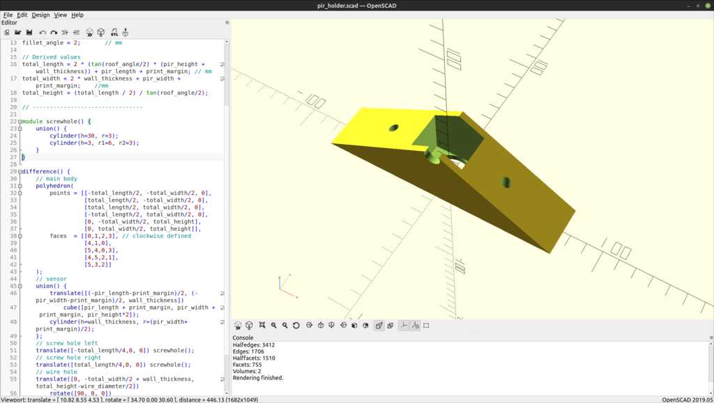
A friend needed a housing for a Passive InfraRed (PIR) sensor in his hedgehog shelter. This was a nice project to try out parametric design in OpenSCAD.
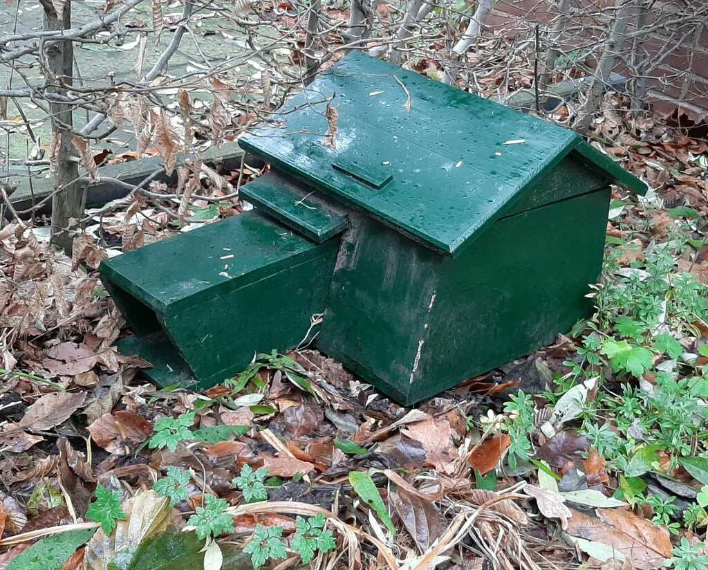 The sensor will be installed inside an angled roof. A few basic parameters are fixed, as the sensor has a defined size and the roof has an angle. All other values can be derived from these parameters. The derivation will be done below and the used formula will be translated to OpenSCAD.
OpenSCAD does not work from a 2d sketch and extruding it, it defines 3d bodies that can be added to (union) or subtracted from (difference).
The sensor housing will be built from a main body shape and then substracting the sensor shape, the screw shapes and the wire shape from it.
The sensor has to fit in the middle. The sensor has a length of 32.6 mm and a height of 30 mm. So that gives us this drawing:
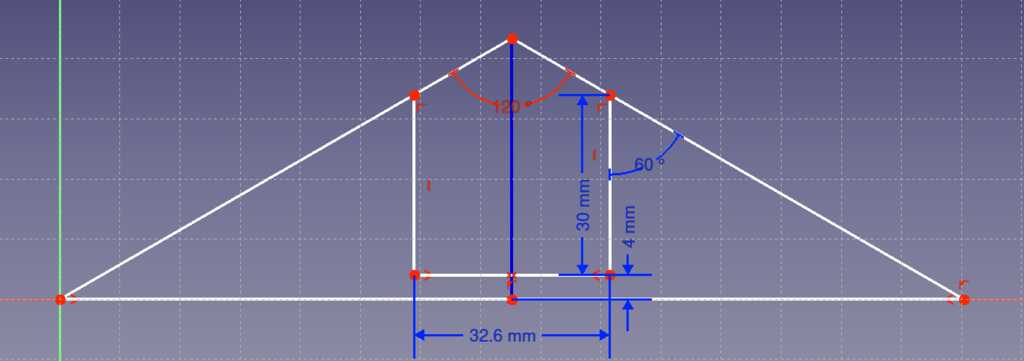 The partial length can be calculated by looking at the right-most triangle. The top-angle is 60 degrees (1/2 of roof angle), the adjacent side is 34 mm (sensor height + wall thickness), so the opposite side is tan(60) = x / 34. This gives x = tan(60) * 34. The formula for the total length is the length of the right triangle + the length of the sensor + the length of the left triangle.
length = 2 * (tan(roof angle / 2) * (sensor height + wall thickness)) + sensor length.
The sensor has to fit in the middle. The sensor has a width of 24.5 mm.
width = 2 * wall thickness + sensor width.
Since the total length is known, the total height can be calculated by the same formula as was used to find the total length.
height = 2 * ((total length / 2) / tan(roof angle / 2))
// OpenSCAD generator values
$fn=100;                // facets

// Given values
pir_length = 32.6;      // mm
pir_width = 24.5;       // mm
pir_height = 30;        // mm
pir_diameter = pir_width;   // mm
roof_angle = 120;       // degrees
wire_diameter = 10;     // mm
wall_thickness = 4;     // mm
print_margin = 0.1;     // mm
fillet_angle = 2;       // mm

// Derived values
total_length = 2 * (tan(roof_angle/2) * (pir_height + wall_thickness)) + pir_length + print_margin; // mm
total_width = 2 * wall_thickness + pir_width + print_margin;    // mm
total_height = (total_length / 2) / tan(roof_angle/2); // mm
The values in the specifications were a length of 32 mm and a width of 24 mm. Measurements showed them to be 32.6 mm and 24.5 mm. This was a good example where parametric modeling reallt shines. Redoing individual size specifications would not have been fun.
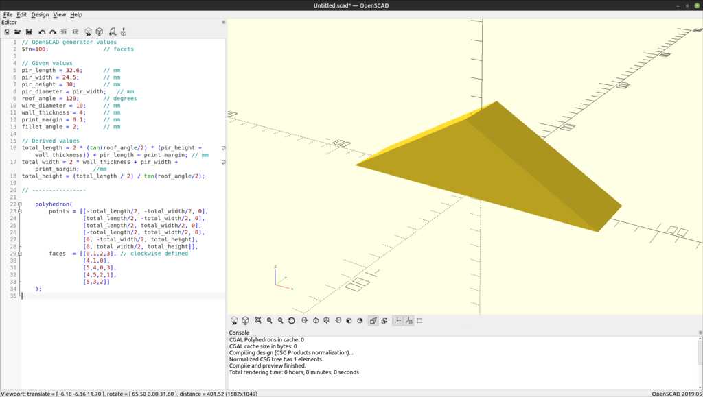
The main body is made of a padded triangle. In OpenSCAD this is created using a polyhedron, the most basic and flexibel shape. First, all points of the body are defined, then faces are created by specifying the points that make up the face. The sequence of the points in a face is important! The direction (clockwise / counter-clockwise) must match for all faces in the body. OpenSCAD has a preference for clockwise.
polyhedron(
  points = [[-total_length/2, -total_width/2, 0],
            [total_length/2, -total_width/2, 0],
            [total_length/2, total_width/2, 0],
            [-total_length/2, total_width/2, 0],
            [0, -total_width/2, total_height],
            [0, total_width/2, total_height]],
  faces  = [[0,1,2,3],  // bottom (clockwise defined)
            [4,1,0],    // front
            [5,4,0,3],  // left
            [4,5,2,1],  // right
            [5,3,2]]    // back
);
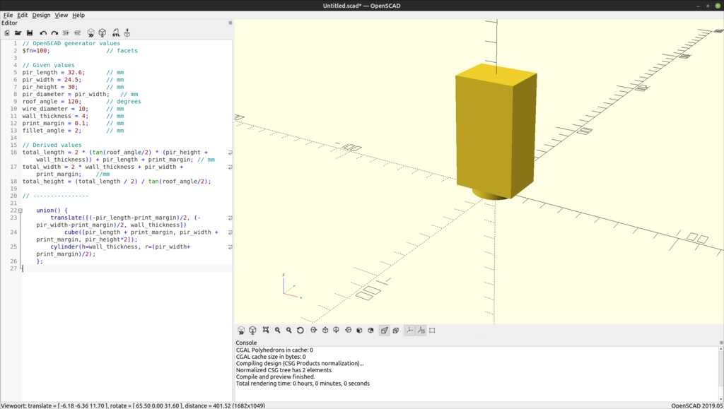
The sensor is made of a cube (for the electronics) and a dome (for the actual sensor). This body will be subtracted from the main body.
union() {
  translate([(-pir_length-print_margin)/2, (-pir_width-print_margin)/2, wall_thickness])
    cube([pir_length + print_margin, pir_width + print_margin, pir_height*2]);
  cylinder(h=wall_thickness, r=(pir_width+print_margin)/2);
};
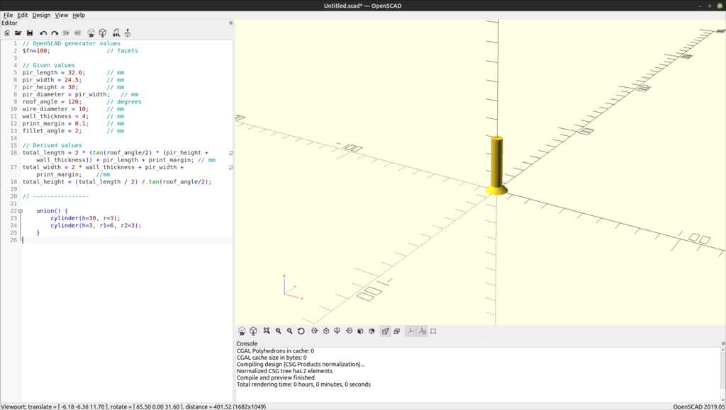
The housing will be attached to the roof with two plywood screws. These holes need to be counter-sunk.
Since we need two screw holes, this is a good place to work with the OpenSCAD modules. The holes can be specified individually (there are only two), but for practice a module was created that is then referenced in the correct location after the desired translation.
module screwhole() {
  union() {
    cylinder(h=30, r=3);
    cylinder(h=3, r1=6, r2=3);
  }
}

translate([-total_lengtpir-housing.scadh/4,0, 0]) screwhole();
translate([total_length/4,0, 0]) screwhole();
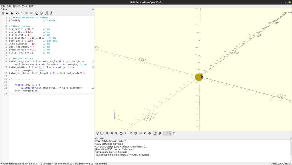
The wire hole is used for guiding a CAT-5 ethernet cable that will provide power and sensor data.
This hole is needed only on one side of the housing, so it will be translated to the correct position.
rotate([90, 0, 0])
  cylinder(h=wall_thickness, r=(wire_diameter+print_margin)/2);
During designing and quick rendering , some artefacts can appear:
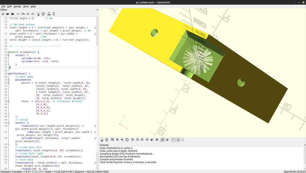
This is caused by two bodies touching each other with zero clearance. The renderer does not know for sure if it should show the hole or the solid face. FreeCAD has the same artefact.
A final render will not have the artefact and show a perfect as-expected image.
< tada.wav >
I do not have a picture of it installed yet, as it still needs to be printed.
The OpenSCAD project file can be found here.
The stl printer file can be found here.
This was a fun week and could be done in between the very busy day-job schedule.
- The creation of all the screenshots and conversion to web-ready versions is smooth. I use ImageMagick’s
convert <filename.png> -convert 1024 -quality 50 <filename.png>as default command. This reduces the filesize to 10%, while still being very readable. - The animation is done using a screen recording in Linux and cropping it using a Kdenlive filter. The export is a h264 movie that is embedded above. The HTML code for embedding was tuned by Philip Hozier.
- THe parametric modeling went well and it adds a level of flexibility to the design.
Applying huge changes to the parameters can cause some weird artefacts, as the constraints are recalculated and suddenly end up on the other side of an edge. - My time estimation was pretty accurate this time, allowing for some additional experimenting with movement in FreeCAD.
- Writing python scripts in FreeCAD can be tricky, as an infinite loop can hang the program. This can lead to data-loss. I fixed it by recreating the file with the lessons I learned in the first itteration.
- Apparently the Cisco people changed something to their Webex software, as the Blender course by Ferdi can no longer be streamed to my system. I will have to pick it up on Youtube at a later time.
- I would assemble various FreeCAD bodies in the Assembly workbench. I used translations and rotations now, but in the Assembly workbench you can simply tell the program that this face should connect to this face (or line). FreeCad will take care of the correct placement.
This is something to investigate for the design of the final project.