 Erwin Kooi
10 - input devices
This week is all about sensors! Yay! A vital part of a control loop.
- Group assignment:
- Probe an input device(s)’s analog and digital signals
- Document your work (in a group or individually)
- Individual assignment:
- Measure something: add a sensor to a microcontroller board that you have designed and read it.
- I already know how to add sensors to a microcontroller
- I want to play with Time-of-Flight sensors and see how sensitive they are
- I want to build a parking sensor
- Pain…
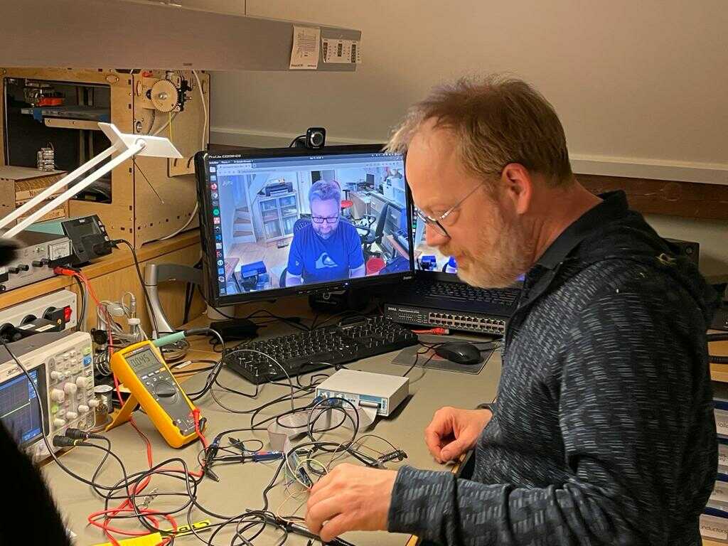
Due to the amount of time that I spent on the previous week, I had to spend more time on my dayjob this week. I could not join the group session at the node. :-(
Together with another student, we organized an alternative online group-event and discussed input devices and worked together on the logic analyzer and discussed project ideas for sensors and how to connect them.
In 2010 I purchased one of the first models of a hobby USB oscilloscope from an Australian startup called BitScope. It is good to see that eleven years later they are still around and are actively developing USB scopes and analyzers.
The model BS326 I have is long superseded by more advanced models, but the software still supports these legacy devices. (Great work!)
I wrote a small arduino sketch to have a square wave send consecutively over three IO pins.
int i = 0;

void setup() {
  // put your setup code here, to run once:
  pinMode(LED_BUILTIN, OUTPUT);
  pinMode(2, OUTPUT);
  pinMode(3, OUTPUT);
  pinMode(4, OUTPUT);
  pinMode(5, OUTPUT);
}

void loop() {
  // put your main code here, to run repeatedly:
  for (i=2; i<5; i++) {
    digitalWrite(i, HIGH);
    delay(100);
    digitalWrite(i, LOW);
  }
  digitalWrite(LED_BUILTIN, !digitalRead(LED_BUILTIN));
}
This was displayed on the logic analyser.
I also have a digital oscilloscope that can do protocol decoding for serial signals. I plan to play more with this in the coming weeks.
For the individual assignment I will be experimenting with a Time-of-Flight (ToF) sensor. I bought this sensor on a break-out board some time ago to build a parking sensor for my tractor.
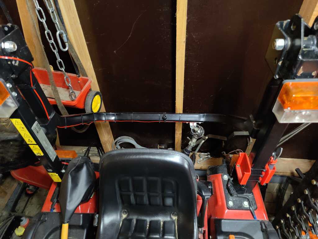
The back of the tractor
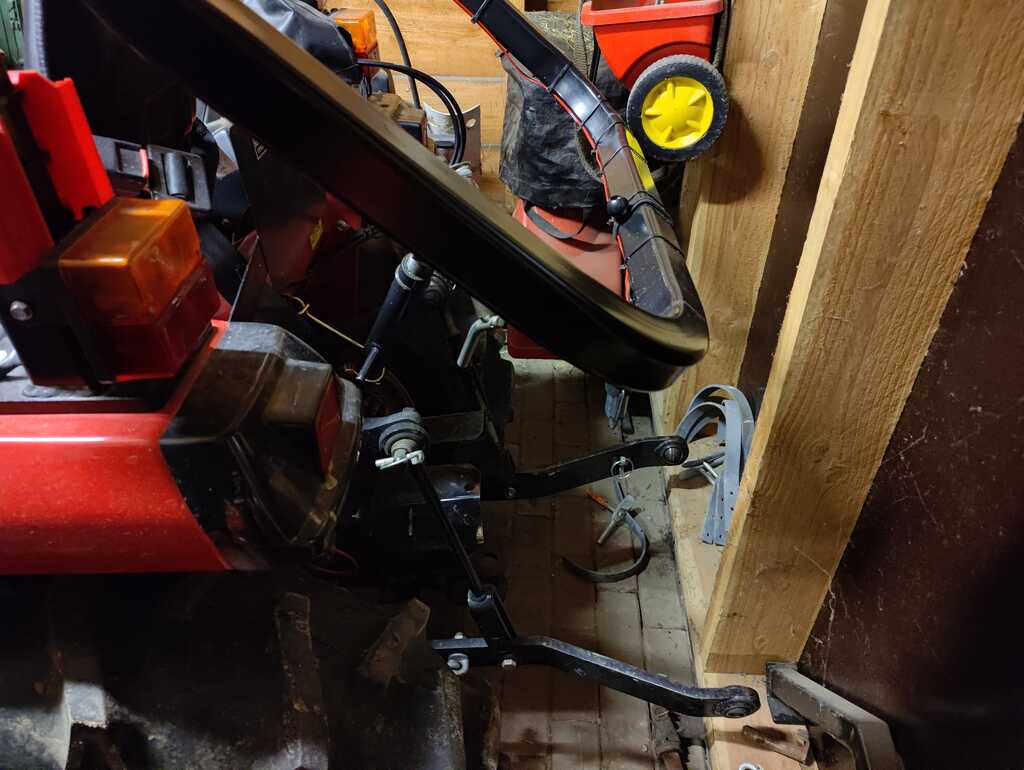
The rollbar that wil be used to measure distance. You can see the distance between the tractor and the back wall.
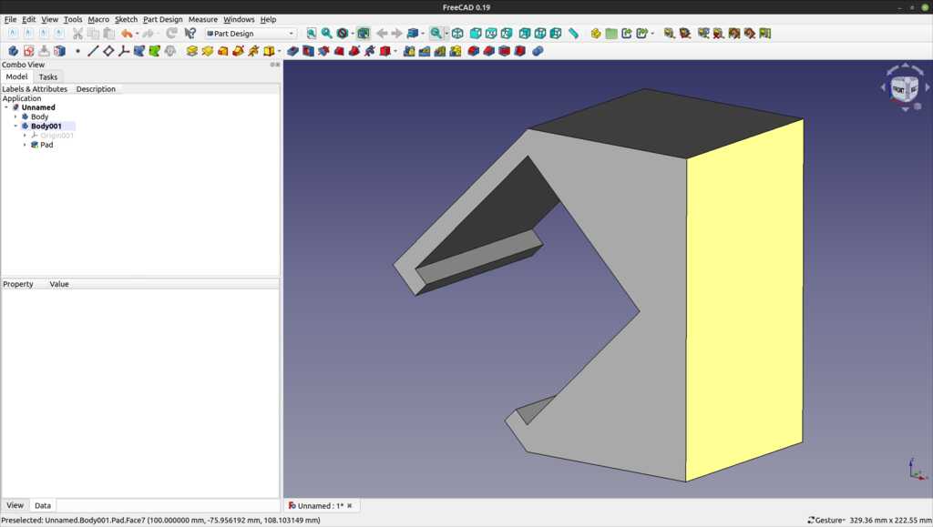
The clamp that will be printed and attached to the rollbar to provide a perpendicular reflective surface.
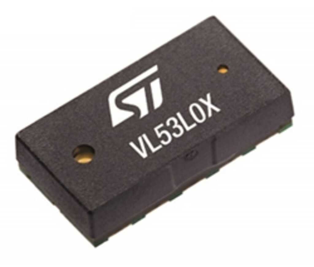 The sensor is a VL53L0x datasheet sensor.
It uses a 940 nm laser to send a pulse and receive a reflection.
The datasheet specifies a range up to 2 meter. I managed to get reliable measurements between 20 and 1292 mm.
Light travels at 299,792,458 m/s in a vacuum. My lab is not in a vacuum and a typical application of this sensor is also not in a vacuum, so the medium where the light will travel in has to be taken into account.
When light passes through a medium, rather than a vacuum, it is slowed down by a factor equal to 1/mu where mu is the refractive index of the medium.
Air (at normal temp and pressure) has a refractive index of 1.0002926, so the speed of light in air is reduced to 299,704,764 m/s. so 87,694 m/s slower. That is 0.03% slower. My calipers are way less accurate, so it will fall within the margin of measuring error and be discarded in my further calculations.
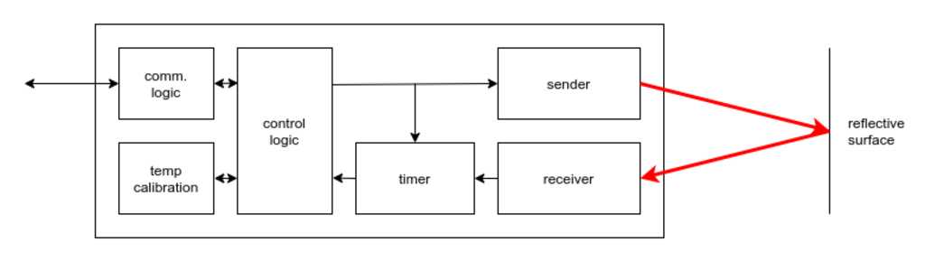
If we translate this to the time domain, then the time light takes to travel 1 meter is 33.3 nanoseconds.
20 mm is the smallest distance I could get this sensor to measure reliably. Since it is a reflective measurement, this means the light travelled double that distance. So the time between the light leaving and returning the sensor is
2 x 20*10-3m x 33.3*10-9s/m = 1.33*10-9s
or 1.33 nanoseconds… Wow.
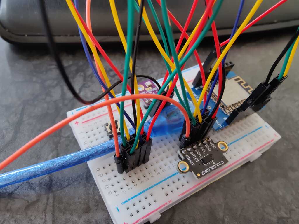
The sensor is quickly hooked up to a D1 mini (a ESP8266 board) using the i2c bus. It is sending the measurements over WiFi on my MQTT home automation bus for quickly displaying the distances on a display.
I used this setup to determine the reliability of the measurements.
The assignment calls for a custom-made board for connecting the sensor.
THe board will use an attiny412 microcontroller and have two LEDs for direct feedback.
It will also have an additional connector for connecting an I2C display in the future.
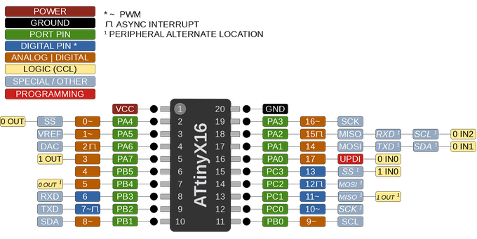
| physical pin | logical pin | component |
|---|---|---|
| 6 | PA0 | UPDI |
| 4 | PA1 | SCA |
| 5 | PA2 | SCL |
| 7 | PA3 | LED |
| 2 | PA6 | TX |
| 3 | PA7 | RX |
| 1 | - | VCC |
| 8 | - | GND |
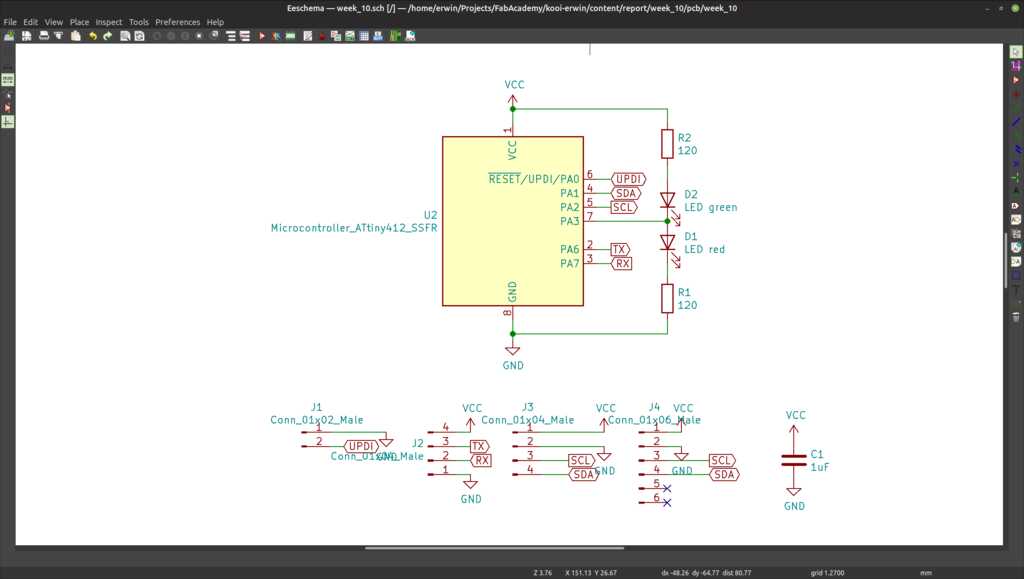
The schematic.
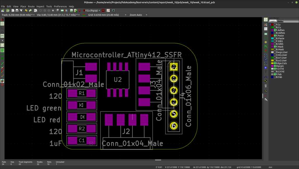
The component placement on the PCB. (NOTE: the copper traces have been hidden for clarity)
I tried using my vinyl cutter and copper tape for creating the PCB. This was not very succesful.
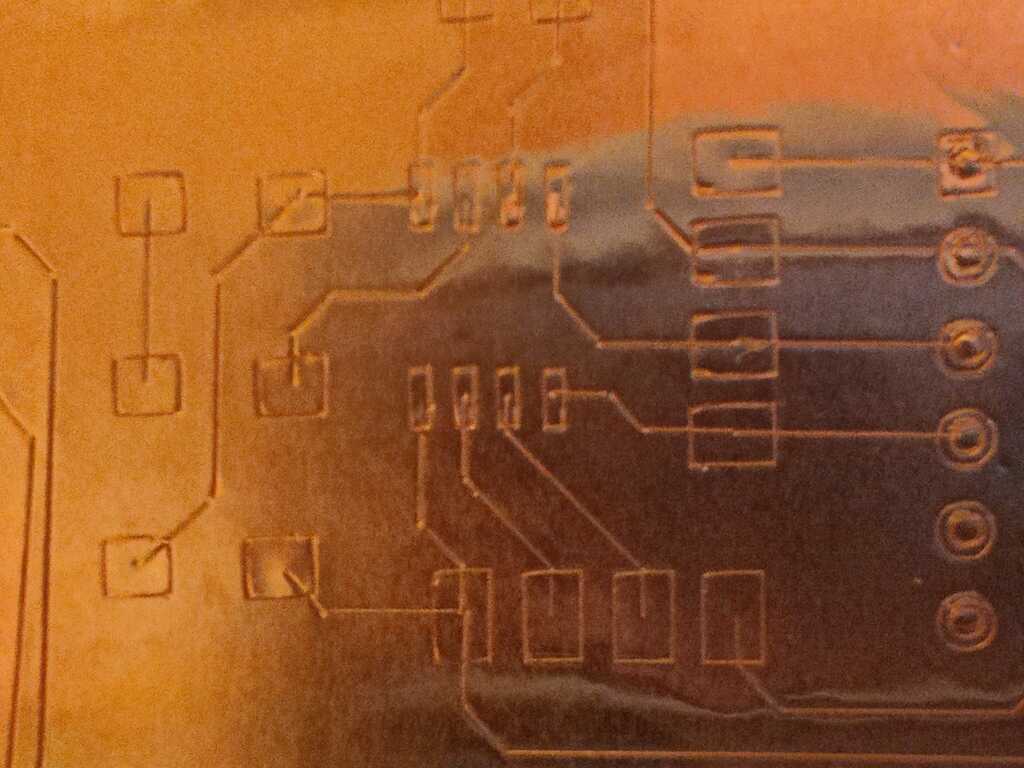
The first export drew the traces instead of outlining them.
The second export created the right outlines, but due to the unregular surface of the tape, not all traces are cut correctly. This can be solved with a cutting mat. I will mill the board tomorrow to get a working board. The cutting of the pcb with a vinyl cutter looks promising, but needs more experimenting.
The Inkscape plugin for controlling my Cameo appears to have a special function to compensate for the knife dragging at the tape. This is a promising feature to test.
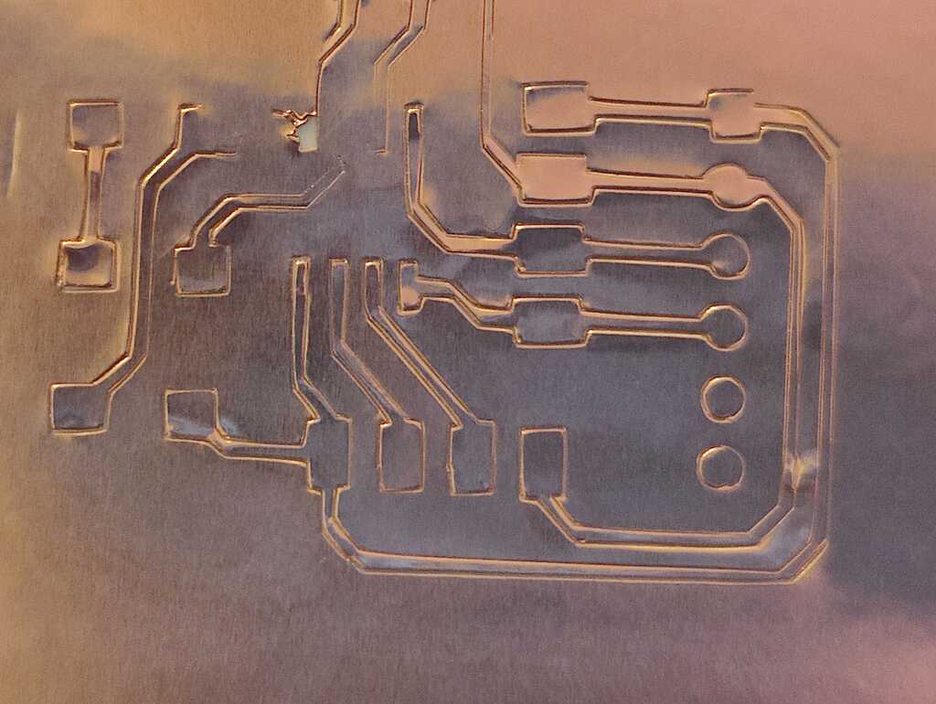
I ended up milling a new board for now.
NOTE
The AdaFruit library uses 17264 bytes. that does NOT fit inside an attiny412
So I decided to write my own library from the datasheets. This was pretty straight forward and required only a few kilobytes.
void I2C_init() {
  // Initialize the I2C bus

  // PORTA.DIR is the direction register for I/O port A
  // where a "0" (default) means input, a "1" means output.
  PORTA.DIR |= PIN_I2C_SCL;
  //   set the data pin to a tri-state during initialization
  PORTA.DIR &= ~(PIN_I2C_SDA);

  // TWI0.MBAUD is the baudrate for the I2C clock.
  //    TWI0_MBAUD is a macro to calculate the value from a given frequency
  TWI0.MBAUD = I2C_SCL_FREQ;
  // TWI0.MCTRLA is a TWI control register
  //   TWI_ENABLE_bm enables the I2C functions
  //   TWI_TIMEOUT_DISABLE_gc disables timeout detection
  TWI0.MCTRLA = TWI_ENABLE_bm |
                TWI_TIMEOUT_DISABLED_gc;
  // TWI0.MCTRLB 0s a TWI control register
  //    TWI_FLUSH_bm clears the internal state of the host
  TWI0.MCTRLB = TWI_FLUSH_bm;

  // TWI0.MSTATUS is a TWI control register
  //   TWI_BUSSTATE_IDLE_gc sets the initial bus state to idle
  //   TWI_RIF_bm, TWI_WIF_bm and TWI_BUSERR_bm clears any interrupt flags
  TWI0.MSTATUS = TWI_BUSSTATE_IDLE_gc |
                  TWI_RIF_bm | TWI_WIF_bm | TWI_BUSERR_bm;

  // PORTA.DIR is the direction register for I/O port A
  // where a "0" (default) means input, a "1" means output.
  //   set the data pin to an output
  PORTA.DIR |= PIN_I2C_SDA;
}

uint8_t I2C_start(uint8_t deviceAddress) {
  // Start an I2C session by setting the client address

  // Clear read/write flags
  TWI0.MSTATUS |= (TWI_RIF_bm | TWI_WIF_bm);

  // Check if the bus has no error
  if (TWI0.MSTATUS & TWI_BUSERR_bm) return 4;

  // TWI0.MADDR is a register for the client device
  TWI0.MADDR = deviceAddress;

  return 0;
}

uint8_t I2C_wait_ACK(void) {
  // Wait till the client has send an acknowledge (after every sent byte)

  // Wait till a read or write have been completed
  while (!(TWI0.MSTATUS & TWI_RIF_bm) && !(TWI0.MSTATUS & TWI_WIF_bm));

  // Clear read and write flags
  TWI0.MSTATUS |= (TWI_RIF_bm | TWI_WIF_bm);
  // Check bus status
  if (TWI0.MSTATUS & TWI_BUSERR_bm) return 4;		// Bus Error, abort
  if (TWI0.MSTATUS & TWI_ARBLOST_bm) return 2;	// Arbitration Lost, abort
  if (TWI0.MSTATUS & TWI_RXACK_bm) return 1;      // Client replied with NACK, abort

  return 0;										// no error
}

uint8_t	I2C_read(uint8_t *data, uint8_t ack_flag) {					// read data, ack_flag 0: send ACK, 1: send NACK, returns status
  // Read a byte from the I2C bus

  // If the host controls the bus
  if ((TWI0.MSTATUS & TWI_BUSSTATE_gm) == TWI_BUSSTATE_OWNER_gc) {
    // Wait till a read has been completed
    while (!(TWI0.MSTATUS & TWI_RIF_bm));
    // Clear read and write flags
    TWI0.MSTATUS |= (TWI_RIF_bm | TWI_WIF_bm);
    // Check bus status
    if (TWI0.MSTATUS & TWI_BUSERR_bm) return 4; // Bus Error, abort
    if (TWI0.MSTATUS & TWI_ARBLOST_bm) return 2;// Arbitration Lost, abort
    if (TWI0.MSTATUS & TWI_RXACK_bm) return 1;	// Client replied with NACK, abort

    // Setup ACK
    if (ack_flag == 0) {
      // Prepare ACK
      TWI0.MCTRLB &= ~(TWI_ACKACT_bm);
    } else {
      // Prepare NACK (to indicate last byte read)
      TWI0.MCTRLB |= TWI_ACKACT_NACK_gc;
    }

    *data = TWI0.MDATA;

    // Send ACK
    if (ack_flag == 0) TWI0.MCTRLB |= TWI_MCMD_RECVTRANS_gc;

    return 0;
  } else {
    // Host does not control the bus
    return 8;
  }
}

uint8_t I2C_write(uint8_t *data) {
  // Write data and return status

  // If the host controls the bus
  if ((TWI0.MSTATUS & TWI_BUSSTATE_gm) == TWI_BUSSTATE_OWNER_gc)
  {
    TWI0.MDATA = *data;

    // Wait till a write has been completed
    while (!(TWI0.MSTATUS & TWI_WIF_bm));

    // Check bus status
    if (TWI0.MSTATUS & TWI_BUSERR_bm) return 4; // Bus Error, abort
    if (TWI0.MSTATUS & TWI_RXACK_bm) return 1;	// Client replied with NACK, abort
    return 0;									// no error
  } else {
    // Host does not control the bus
    return 8;
  }
}

void I2C_stop() {
  // Stop I2C session

  TWI0.MCTRLB |= TWI_MCMD_STOP_gc;
}
This worked well. Now on to the datasheet of the VL53V0X…
WARNING!
The manufacturer of the VL53V0X (ST microelectronics) does NOT specify control registers in the datasheet. They provide a (horrible) API that you have to use. Their excuse is that this is a very complicate sensor (true) and that we mortal developers should not worry our little heads trying to control it (da fuq?).
So I have four options:
- reverse engineer the API (which cross-references itself like crazy)
- use another sensor
- reverse engieer the much more readable Adafruit library
- switch to a microcontroller that can hold the Adafruit library
I redesigned a board around an attiny3216 and made connectors for every type of bus. Serial, I2C (2x), SPI and UPDI. This microcontroller has enough memory to fit the Adafruit library and can be used for the assignment of week 12 as well.
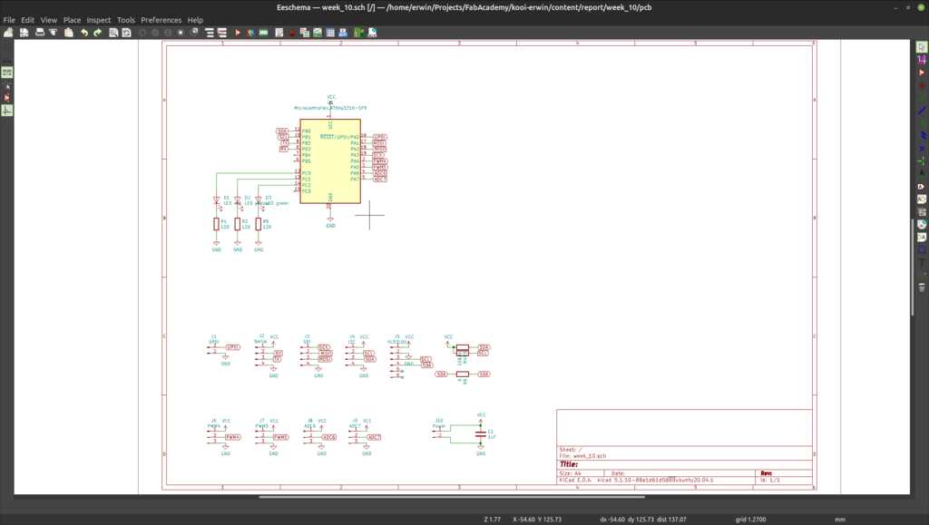
KiCAD schematic with the attiny3216
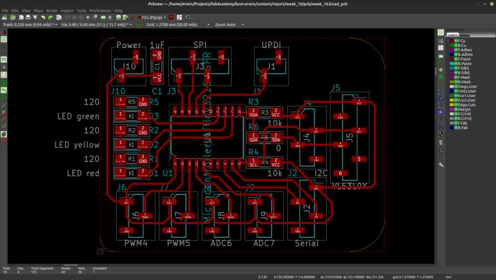
KiCAD pcb with the attiny3216
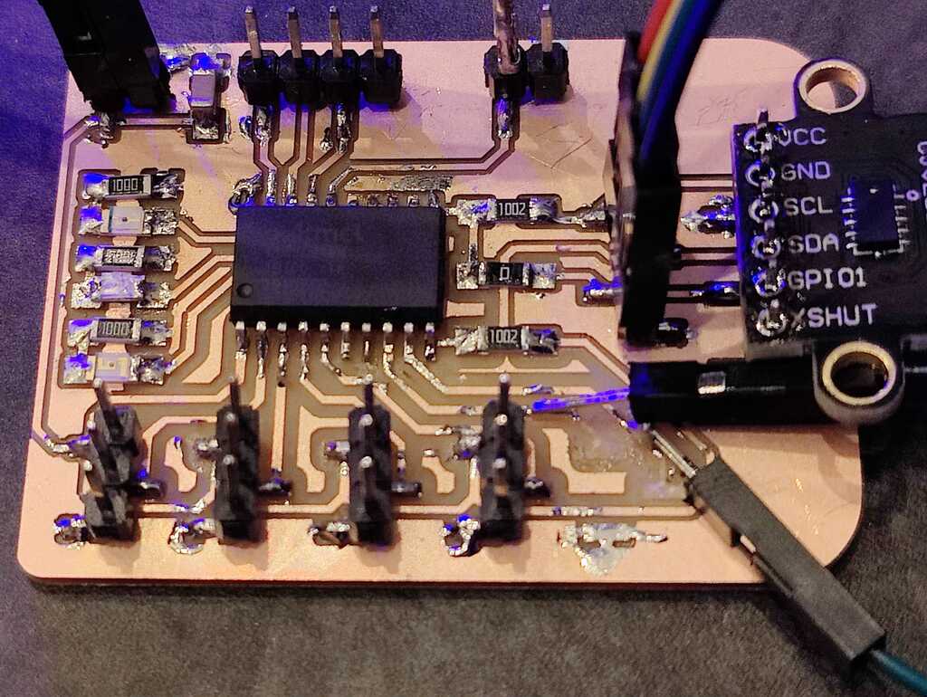
After milling and soldering the board, let’s quickly test if the board is working.
void setup() {
  pinMode(10, OUTPUT); // GREEN LED
  pinMode(11, OUTPUT); // YELLOW LED
  pinMode(12, OUTPUT); // RED LED
}

void loop() {
  digitalWrite(10, HIGH);
  delay(250);
  digitalWrite(11, HIGH);
  delay(250);
  digitalWrite(12, HIGH);
  delay(250);
  digitalWrite(10, LOW);
  delay(250);
  digitalWrite(11, LOW);
  delay(250);
  digitalWrite(12, LOW);
  delay(250);
}
This worked and the LEDs are blinking happily.
Unfortunately (1), the traces of the RX and TX of the serial connector came off, so I had to fix this by directly soldering wires to the traces.
:Serial fail
Unfortunately (2) I swapped the SDA and SCL pins. So the i2c bus will work fine, but the pins are swapped on the board and the sensor cannot be directly soldered on. Nothing a quick jumper wire cannot fix. :-)
This will be fixed in later revisions of the board.
I will be using AdaFruit’s vl53l0x library. This will prevent library conflicts in later weeks when I am adding output devices to the same board. The attiny3216 is big enough to contain it (and then some).
#include <Wire.h>               // The general library that includes i2c
#include "Adafruit_VL53L0X.h"   // The Adafruit library for the vl53l0x

#define LED_GREEN     10        // The pin for the green LED
#define LED_YELLOW    11        // The pin for the yellow LED
#define LED_RED       12        // The pin for the red LED
#define LEVEL_TOP     250       // The level between safe and attention (in mm)
#define LEVEL_BOTTOM  100       // The level between attention and danger (in mm)

Adafruit_VL53L0X sensor = Adafruit_VL53L0X();

void setup() {
  // Setup IO pins
  pinMode(LED_GREEN, OUTPUT);
  pinMode(LED_YELLOW, OUTPUT);
  pinMode(LED_RED, OUTPUT);

  // Setup serial interface
  Serial.begin(9600);
  while (! Serial) {
    delay(1);
  }
  Serial.println("Range sensor starting...");

  // Setup i2c with default pins
  Wire.begin();
  if (!sensor.begin()) {
    // Test if we see the vl53l0x sensor
    digitalWrite(LED_RED, HIGH);
    Serial.println("VL53L0x sensor not found! Aborting."));
    while(1);
  }
  Serial.println("Range sensor started!");
}

void loop() {
  VL53L0X_RangingMeasurementData_t measure;

  sensor.rangingTest(&measure, false);       // Perform a measurement
  Serial.println(measure.RangeMilliMeter);

  if (measure.RangeMilliMeter >= LEVEL_TOP) {
    digitalWrite(LED_GREEN, HIGH);
  } else {
    digitalWrite(LED_GREEN, LOW);
  }
  if (measure.RangeMilliMeter < LEVEL_TOP &&
      measure.RangeMilliMeter > LEVEL_BOTTOM) {
    digitalWrite(LED_YELLOW, HIGH);
  } else {
    digitalWrite(LED_YELLOW, LOW);
  }
  if (measure.RangeMilliMeter <= LEVEL_BOTTOM) {
    digitalWrite(LED_RED, HIGH);
  } else {
    digitalWrite(LED_RED, LOW);
  }
  delay(500);
  digitalWrite(10, LOW);            // this will blink the green LED
  delay(250);
}
The KiCAD project file can be found here.
The KiCAD schematics file can be found here.
The KiCAD pcb file can be found here.
The source code can be found here.
This was an interesting and frustrating week…
- The sensor is very accurate and will fit perfectly for the purpose.
- The Adafruit libraries abstract all the apparent complexity of the sensor.
- Writing your own i2c library is surprisingly easy when using the already present i2c circuitry in the microcontroller (even though I ended up using the Adafruit library in the end).
- The attiny412 has not enough memory to hold the libraries. Moving to another microcontroller fixed this.
- The PCB has clock and data lines swapped. Using jumperwires to connect the sensor fixed this.
- I would compile the code to see how big it is before selecting a microcontroller.
- I would check the datasheet of the sensor to see how easy it is to write a custom library for it.
- I would tripe-check the schematic to see if I have the communication pins wired correctly.
- I would use tweezers to hold the SMD connectors when soldering. This makes soldering the pads go quickly and limit the risk of traces becoming loose from the pcb.