10. Mechanical Design
This weeks assignment was to create a mechanical machine that includes a moving mechanism with actuation and automation and is designed to have a specific application.
New Group Project
This week’s assignment was a group effort, and you can see our completed machine on CDL FabLab Mechanical Design group assignemnt.
The assignemnt involved us working together to design and build a automated cookie cutter together.
Group Members:
This project is an update/remake of a machine we made in a previous fab academy cycle. You can see my documentation of the old project below Old Mechanical design project.
Working together
-
All the group members contributed to the brainstorming and ideation of the initial project and then again for the changes we made to from the older project to this new one.
-
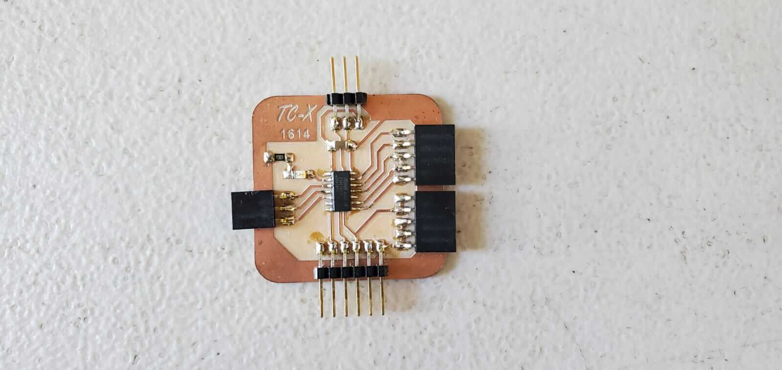
Terrence Carew, spearheaded the microcontroller design since at this point he was the most confident and he’s totally awesome at soldering. But we all helped him along wherever we could.
-
We all also helped with the final assembly.
-
Since we had made most of the larger parts in the Old Mechanical design project. The rest of the work to be done was mainly designing and making molds to be sloted into the main machine.
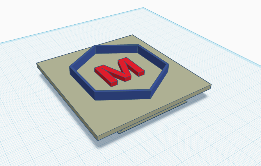
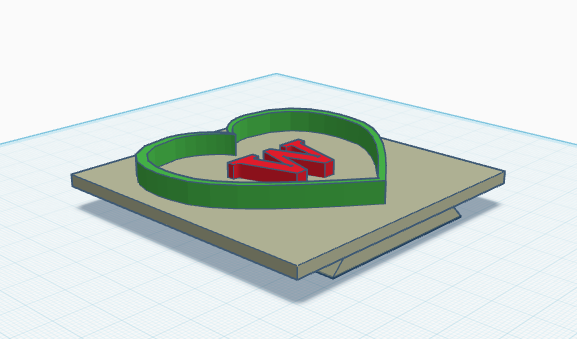
My molds
-
I designed my molds in TinkerCAD.
-
I made two mold:
-
These molds have a taller outer edge for cutting the dough, and a shorter inner protrusion to stamp the dough.
-
A Hexagon with a M for “Machine”
-
A Heart with a W for “Week”
-
OLD Group Project
Our group worked on an older version of the group assignment in an earlier cycle of fab academy. At the time we hadn’t yet recieved all the components for our digital electronics portion. So we pivoted and made a design using more old school relays and switches. I am leaving this older version project here for anyone who is interested since we put allot of work into it at the time. It’s also useful to see what changes we made to the new version on New Mechanical Design group page
The new group project very similar except that the control system has been updated to use a microcontroller.
Machine description:
We are calling our machine design the “Mold Jammer”. This machine is designed to automate the continuous casting of objects by pressing and releasing of interchangeable mold plates against a pliable medium.
This first iteration of our design is mounted vertically.
- Once the start switch is pressed, the device pushes a mold “head” downward till it comes into contact with a lump of pliable casting medium on a flat horizontal plate.
- The pressure from the mold squeezes the medium into the desired shape with any excess exiting through a small access hole within the mold itself. This leaves just a small contact point between the molded object and the excess material which can be easily separated.
- Once the mold finishes squeezing the medium it then retracts upwards leaving behind the finished molded object behind.
- After the mold head raises to a predetermined distance, it then changes direction moving back downwards to shape a new lump of medium.
- The time and distance the head moves can be easily adjusted to allow enough time to remove the finished material and replace it with a new lump of material to create another molded object.
- In this current iteration the unmolded medium has to be continuously reapplied and the molded objects continuously removed.
- The process repeats itself automatically until the off switch is activated.
We also have future upgrades planned for our design which would increase its versatility and automation.
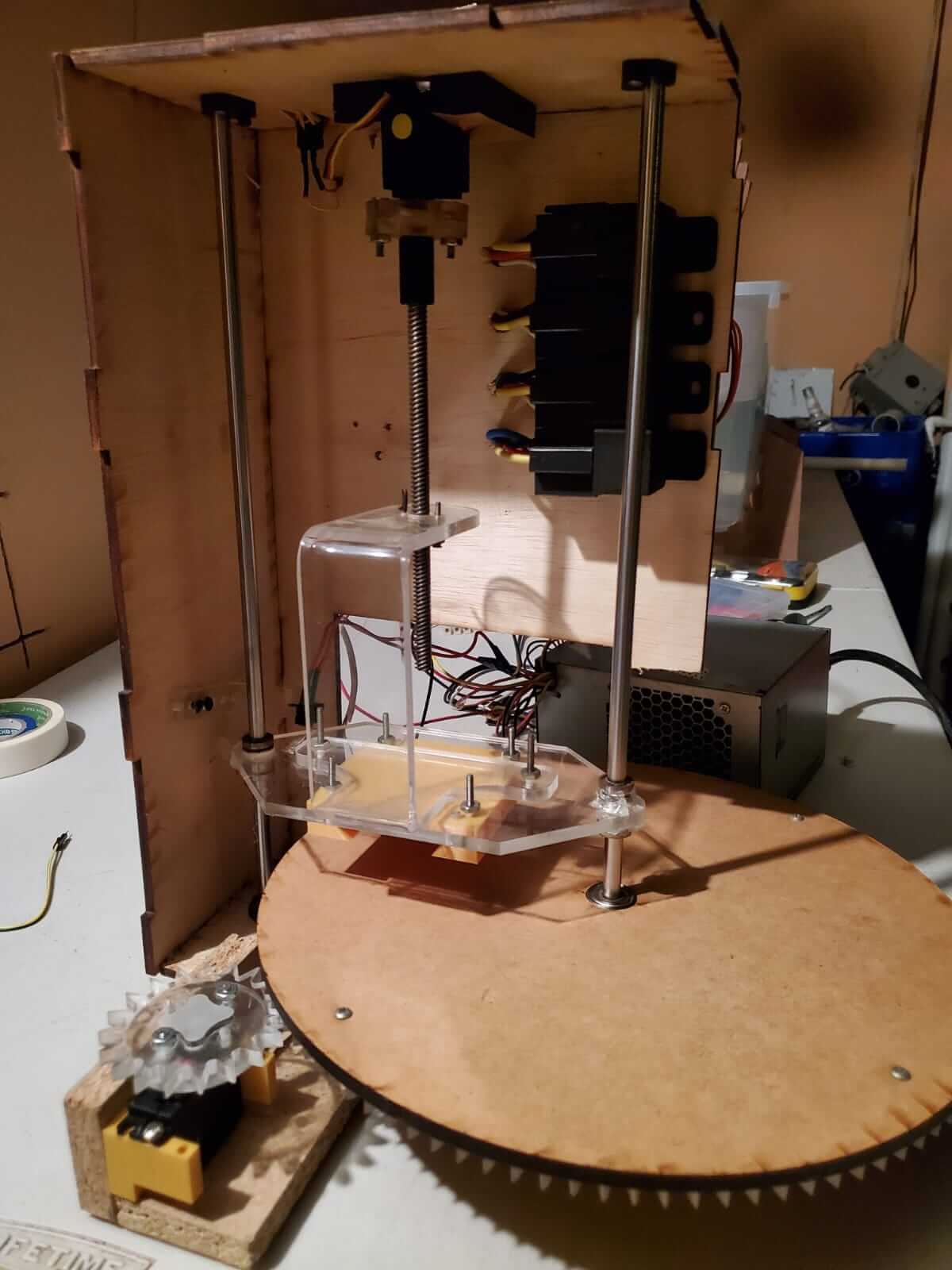
Mechanical Motion:
- The motion of the mold head is facilitated by a moving plate connected to a bass nut driven by a turning threaded rod.
- The moving plate is supported by two linear shafts, one on either side, each running through a slide on the plate.
- The plate is positioned in front of the threaded rod and is mounted on a U-shaped arm with the plate and brass nut on opposite sides. This allows for enough clearance between the plate and the top end of the threaded rod so that the plate can move a far enough distance to be useful for a variety of mold thicknesses.
- The plate was positioned in front of the rod rather than offset for two reasons. 1) So that the center of the mold is perpendicular to the rod creating the motion. This helps ensure that the pressure applied by the mold is done so evenly. 2) So that there is more clear space around the plate and mold, giving us more options in how we can implement some of our planned future upgrades.
- The plate and armature were made from laser cut 1/4 inch acrylic. The arm being heated and bent to the U-shape.
- A mold holder was 3D printed and affixed to the moving plate with screws. This holder had a slotted female groove so that different molds could be easily swapped in and out. Mold pieces were all made with a matching male grove to facilitate this quick change feature.
- Although this first iteration of our design has the mechanism moving vertically, some of our future upgrades would work better with horizontal motion. Our entire machine can be oriented sideways to facilitate this.


Frame and support:
- The main body of our machine was made using laser cut 3/16” plywood panels that were glued together.
- The body of the machine is essentially an open “box” with 2 windows cut out.
- One window is positioned where the medium to be molded would be placed. The other window is positioned on one of the side panels to make access to the molded objects easier, and also to facilitate some of the future upgrades.
- Although the current design is strong enough for our current application, future designs may need more pressure to be able to be applied to the molds, and a stronger frame needed. In this case we would likely replace the frame’s panels with thicker CNC cut wood pieces.

Power and control:
- The main powered mechanism for our machine, the turning threaded rod, is driven by a modified Hitec HS-422 servo motor. We chose this motor because they generated enough torque for our purposes, but are also easily modified (internally rewired) to be controlled by a direct voltage signal instead of the originally designed PWM signal.
- The range of motion of the mold plate is controlled by the placement of two limit switches. One is placed so that it is hit by the moving plate when the plate reaches the mold’s finished position. The second is positioned so that it is struck by the moving plate when the plate retracts to the desired position so that the procedure can begin the next descent. Both limit switches are placed on brackets that are designed to be easily repositioned so that different thickness molds can be used.
- The mechanism for controlling the motor is done by wiring the motor, limit switches, on button and power supply to 4 relays. The relays being wired in the configuration needed to get our desired behavior.
- The wiring for all our components were connected by two 12-terminal terminal blocks. This was done instead of direct connections so that the wiring schematic can be easily modified when we implement some of our planned future upgrades.
- The activation (on) switch is a simple push button switch.
- The entire machine is powered by an old repurposed computer ATX power supply with the start signal wire jumpered to ground so that it automatically starts up when its hardware switch is turned on. The PSU’s hardware switch then becomes our off switch when we want to turn off.

2022 control update:
- Since we didn’t get the equipment last year to build circuit boards in time, we used relays and limit switches. This time around we were able to build our proper microcontroller control board to generate the same behavior.
- We have a small problem with the coding for the conveyor servo, so that single aspect isn’t working in the video, but we are working on the solution.


Future upgrades:
- Double sided molds. The machine can be easily modified to utilize double sided molds. This will allow for more shapes of finished objects to be created.
- Carousel for automated loading of medium and removal of finished objects. This upgrade involves the use of a second motor driving a “Lazy Susan” type carousel that rotates together with the mold plate. This will allow us to preload multiple lumps of unmolded medium so that many objects can be molded in a row without the need to be manually removed.
- Side mounted molds and automated medium injection (together with double sided molds). Side mounted molds would allow us to simply drop the finished object once molded into a receptacle below. Combining this with an automated continuous feeding mechanism for the unmolded medium would result in a fully automated molding production machine.
- Upgraded timing and controls. This would allow us to add wait periods to our motor control rather than just forwards and backwards motion. This would be necessary if we wanted to use a medium that requires some time to cure before hardening. The wait state would also be necessary for the side mounted molds and automated medium injection, since the molds would have to be held in place while the medium is being injected.

