7. Computer Controlled Machining
This week was spent learning to use the “large” CNC router in our lab and creating a CAD design to use with it.
Group Assignment
Working as a group, me and the other fab academy students here (Cristopher Proute, Terrence Carew, Nervene Bhagwandass, Marvin Holloway, Ravi Baldeo) investigated the recommended safety procedures for our large X-carve CNC router, and our labs own safety precautions. We also ran a tests to check the alignment and toolpath on the machine. You can see our results here.
Individual assignment
This week’s activity was to design and mill something big. The CNC router in our lab is a first generation X-Carve 1000mm and has a cutting bed size of 750mm x 750mm x 65mm. Because if these restrictions I chose to design a card table with a rounded square surface of 600mm x 600mm and a height of 700mm. I chose to make the table out of 1/2 inch thick MDF since:
- MDF has a nice smooth surface
- MDF is relatively easy to mill
- MDF isn’t too expensive
- 1/2 inch thickness will give the table more than enough strength
- We already had it in stock at the lab
I designed the table in Fusion 360 and made the toolpath in Easel.
Designing in Fusion 360.
The table would be designed as three 2 dimentional pieces, each eventually being their own cut on a run of the X-carve: 2 leg panels that interlock at 90 degrees to one another and a table top that rests on top with grooves.
Design
The design is of a card table, mainly for playing all fours, which is pretty much the national card game for Trinidad & Tobago. Its a 4 player game.
The table was designed to be easily assembled and dissassembled. As such I avoided making the interlocking tongues and grooves particularly snug. It is however snug enough that the table doesn’t wobble once assembled. All the assembled pieces are kept in place mainly by gravity.
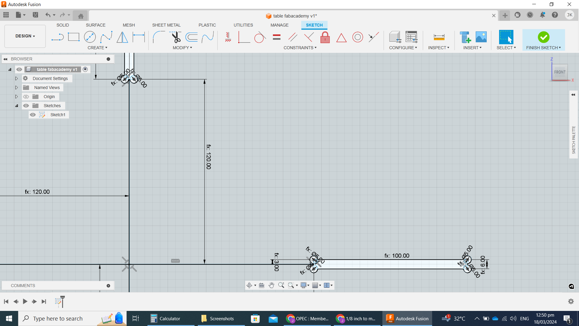
The table was designed in 2D using the sketch tool in “solid” tab of fusion 360.
The 2 leg pieces are mostly duplicates of one another. The only difference is that one side has the slot running from the top of the leg to the middle, and the other has the slot running from the bottom to the middle. This means that they can interlock with one another at 90 degrees, creating the four “legs” of our table.
The table top is degined as a 600mm square with a 50mm fillet so it has gentle corners. There are 4 tongues on the combined legs, these slot into the 4 grooves on the tabletop.
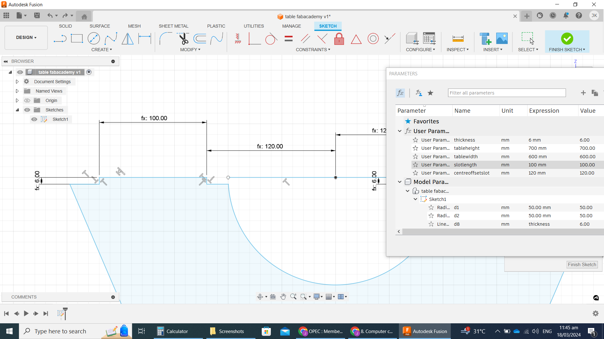
Parametrics
I used parametric variables for most key dimentions that I might want to alter later on. These were:
- Thickness. The actual thickness of the MDF sheet used, needed for determining the width of the slots(mortise) where the MDF tongues(tenon) from another piece would fit. It is also used to determine the height of the tenons on the leg pieces, so that the table top would be flush with the tenons once assembled. I used 6mm as a placeholder here while doing initial design work, but the actual measured value was 12.31 mm (pictured below). The final parameter used was 13mm, so that the final grooves weren’t so tight that assembly and disassembly was difficult.
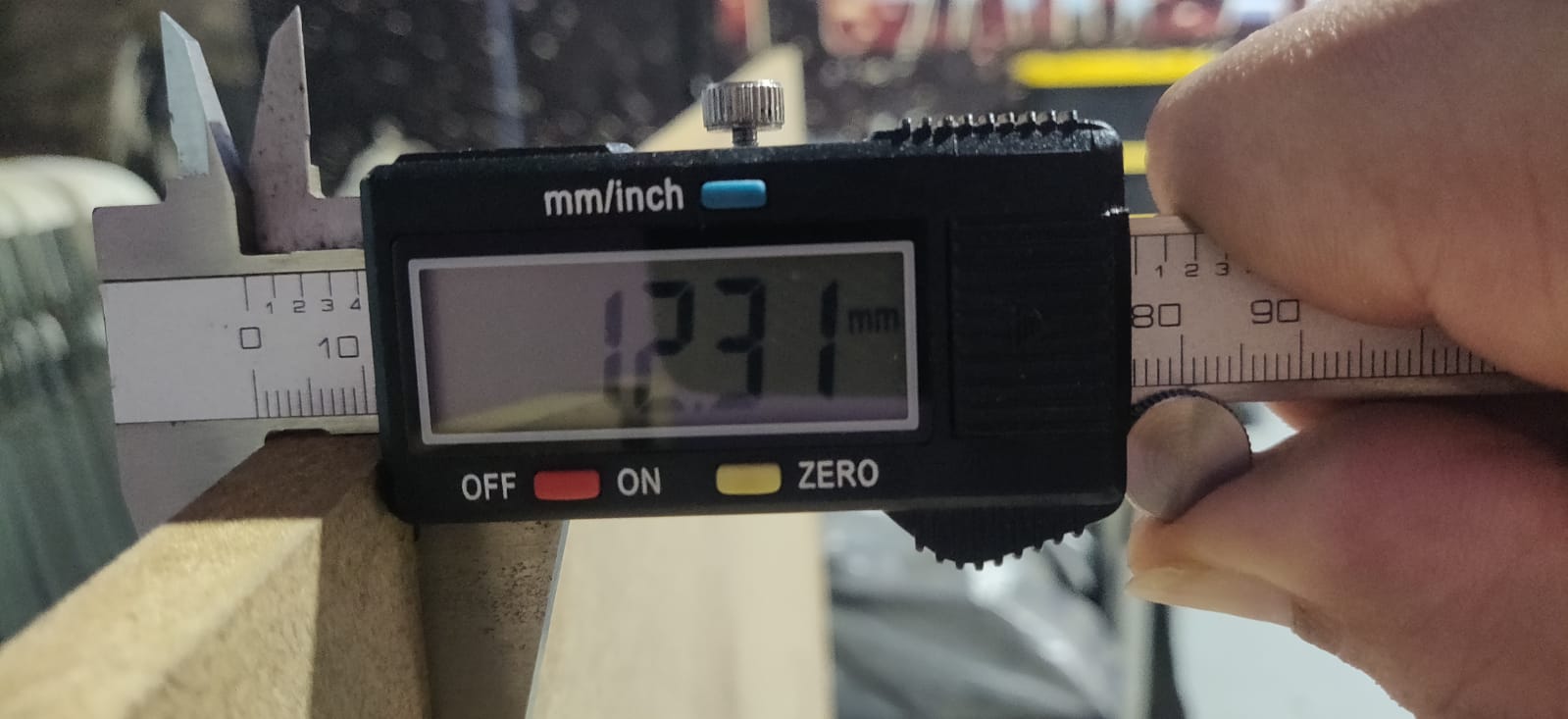
-
Table Height. The height of the overall table, which is the same as the height of the leg pieces. This goes from the bottom of the feet to the top of the tables surface. This is because the top of the leg pieces actually have tongues that pass through the table tops slots, so the leg pieces full height is flush with the tabletop surface. This was set at 700mm.
-
Table Width. How wide is the square table surface. Set at 600mm but could have been increased to the max of the Xcarve (750mm).
-
Slotlength. How long to make the table top slots, as well as the tongues on the leg pieces. set to 100mm.
-
Centre Offset Slot. How far fron the centre of the table do the slots start. this parameter makes sure that the slots on the table top and the tongues on the legs are properly alligned. Set to 120mm.
-
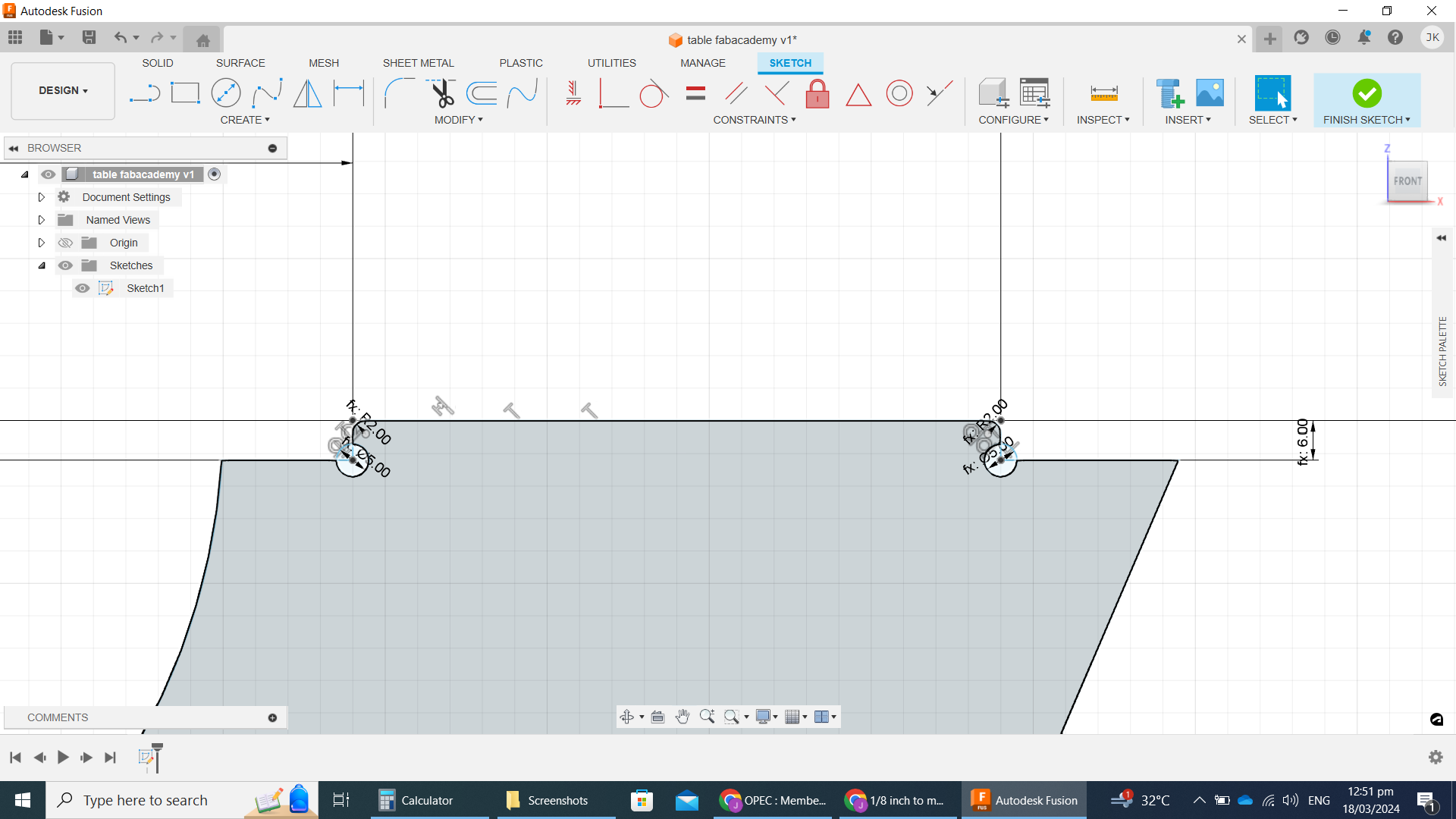
Fillet. Set to 2mm. this was a small curve set on the lengthwise edges of the tongues. This made insertion into a tight slot slightly easier. If insertion was still too dificult, we could increase the fillet parameter (and perhaps also the groove width by increasing the thickness parameter slightly). Or we could reduce this parameter if we wanted more of the tongue to be completely flush with the tabletop.
-
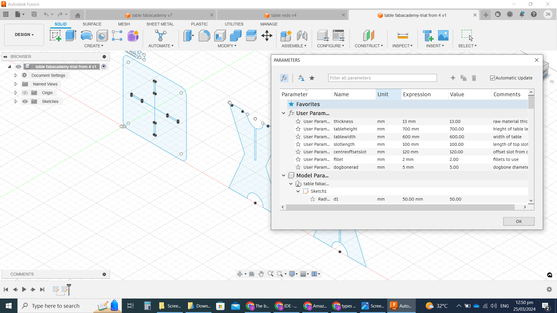
Dog Bone Rad. The dog bone radius. We used dogbone fillets throughout our design, in every inside corner that would be making contact with another interlocking piece. CNC milling is limited by the fact that a round milling bit can’t make a perfectly straight inside corner. When cuttin an inside path, the pathing software errs on the side of cutting less of the corner rather than “cutting off more to make sure that all the designed material is remover”. A thinner milling bit could come closer, but still can’t get it perfect. Our initial design is made as though perfect inside corners are possible. To allow all the pieces to fit as intended, we manually added dogbones to each inside corner. We set each dogbone fillet diameter as a parameter so that we could easily alter it in the future. This would come in handy if we change the diameter of the endmill used, or if we want to minimize the esthetic impact of the dogbones in future reruns of this job. We set this parameter to 5mm.
- Here’s the full list of Paramtric terms we used:
File export
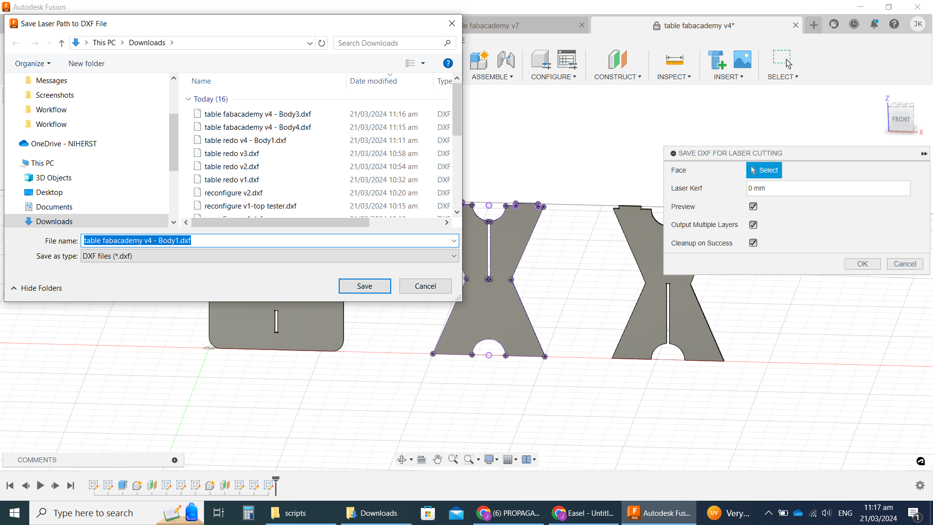
While experimenting with the Easel software, we realised that it worked well most consistently with a DXF file format of an extruded 2D drawing.
To achieve this I extruded my 2D drawing using the “Extrude” tool under the “Solid” tab in Fusion 360.
I installed a Fusion 360 addon called DXF for Laser. This addon performed some additional formatting of the exported DXF file that weren’t done by default in Fusion 360. It also had the added benefit of doing the file export much fastly than Fusion 360 does natively. (once installed the DXF for Laser option is located in the “Create” dropdown of the “Solid” Tab). I set the “Laser Kerf” to 0 in setting up the export.
It also easily allowed me to export each component of the overall design as a seperate file, which made things easier when loading into Easel. Here are the files:
- Table leg top DXF
- Table leg bottom DXF
- Table Top DXF
- Full Table CAD (native) Fusion F3D
- Full Table CAD DXF (not through Addon)
Pathing software
I used Easel to do the pathing on our Xcarve and control the machine as well. We mainly use this Web based tool because it was the recommended tool by Xcarve, so it works well and is well documented. The free version also has all the tools we currently need.
Material - From the Easel interface I selected the material to be cut as 1/2 inch MDF. This works out to 12.7mm, so just slightly bigger than the 12.3mm I measured for our material thickness. But I left it at the 12.7mm.
Bit - The bit I used was a Carbide 3D #102, a 1/8” shank, 1/8” cutter 2 flute flat upcut bit. There were smaller bits available at the lab, which would have allowed for smaller dogbones, but they still had a 1/8” shank, and the cutting length was shorter than the material thickness, so that would have caused problems. In the Easel interface I set the endmill bit used to “1/8 inch”. The free version of easel only allows limited bit selection, so the closest bit I was able to select was called “upcut 1/8 inch single flute”, but I believe it wouldn’t make a difference. The option exists in Easel to use 2 bits, a roughing and detailing bit, but I chose to use the single bit option. In the future I may trial using a 1/4” bit for roughing and 1/8” bit as detailing.
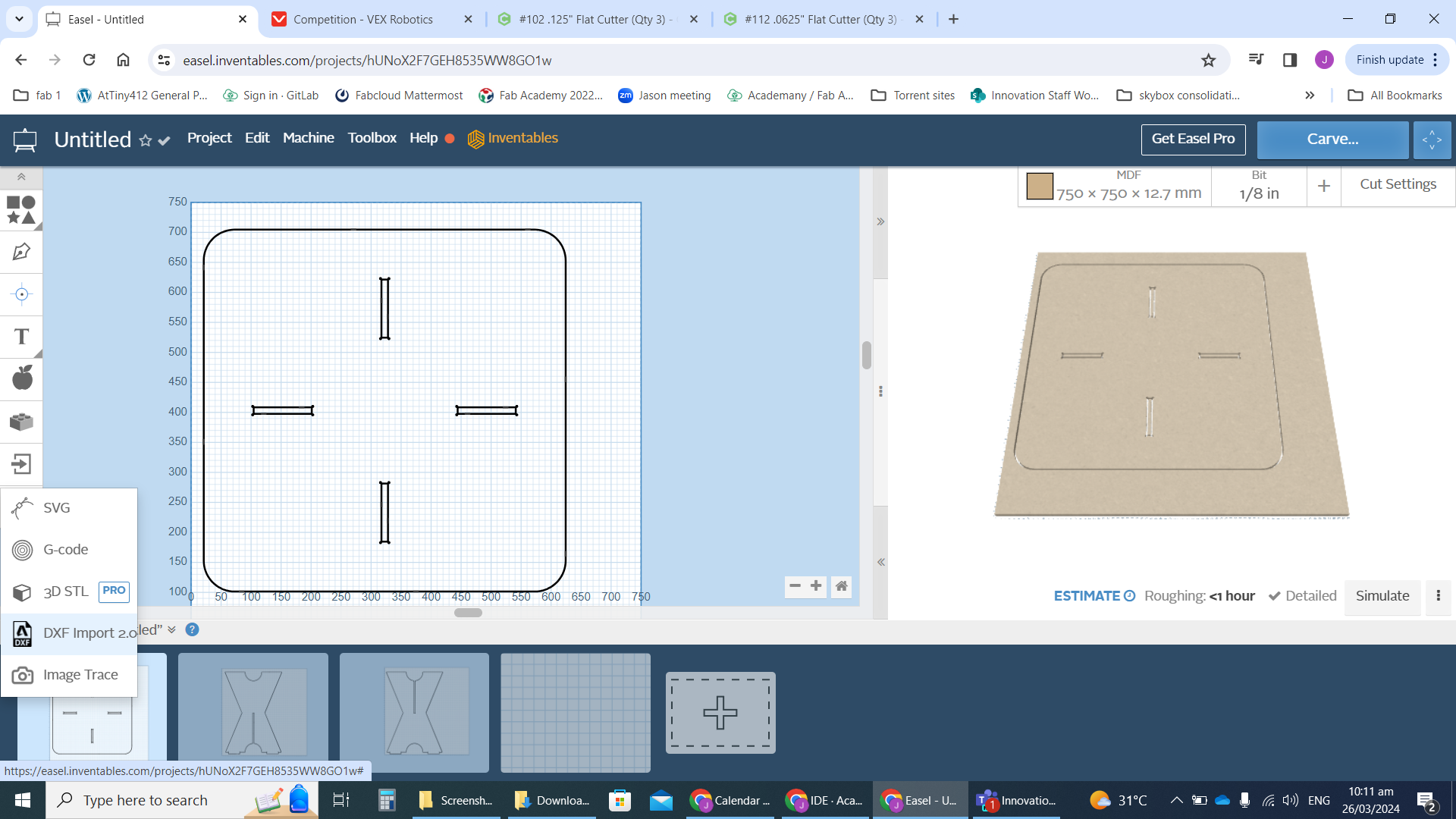
loading files - To load the files I used the IMPORT -> “DXF Import 2.0” selection from the left side panel. After each file was uploaded, I added a new Workpiece in the bottom panel and loaded the next file in a seperate “workpiece”. Each file, which corresponds to each of the 3 sections, was placed on its own workpiece to be cut as a seperate job. For each continuous line in the design I had to click on it and specify details:
-
Cut Path: on shape path, inside shape path, outside shape path, or clear out pocket. I only used inside or outside depending on the line. Inside for grooves, outside for everything else.
-
Tabs: # of tabs to use on each seperate line. I used 2 tabs on the small lines (table top grooves), and 8 on the long ones (all other cuts). I shifted the tabs around to locate them on straight cuts (so that they could be easily smoothed out after removing). I increased the tab height from 2mm(default) to 4mm to make them stronger, and left the length as default.
Cutting
We cut 3 pieces of MDF to use from a full 4’ x 8’ sheet. This was done using a friend, a table saw, and all proper safety procedures and gear. We cut a 2.5’x 2.5’ piece for the top, and two 3’ x 2’ pieces for the legs. Although we tend to work in metric, sheets of large material almost always come in 4’ x 8’ sheets. I used these dimentions because it left us with ample extra space to attach our clamps for the cut, but also left behind panels of materials that were still big enough to be useful.
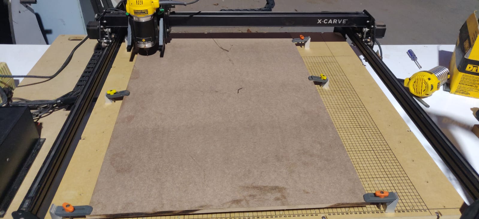
For each run, I clamped down my material on top the wasteboard using 6 contact points around the edge.
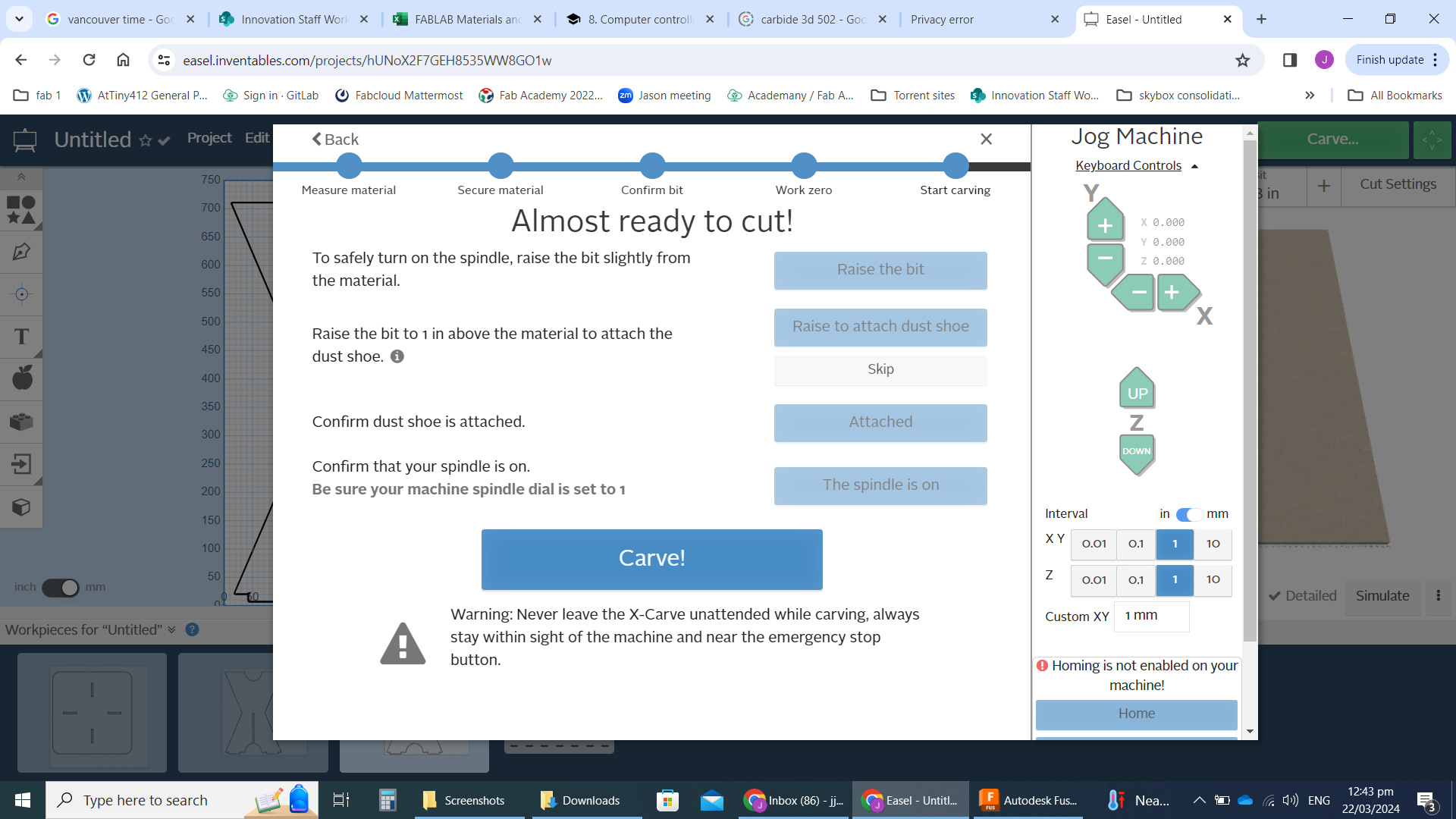
The final steps to be used in the Easel software was to set up the cut. There is a small checklist prompted by Easel when we click the “Carve” button in the top right. (these options are only available if the Xcarve is on and connected to the computer via USB):
- Manually Jog the the spindle so that the tip of the Endmill bit is lined up with the bottom left corner of our material (X & Y plane). Also adjust the height of the bit’s tip so it is just above the material surface (Z axis).
- If attaching the dust shoe, we are prompted to raise the spindle so that the shoe can be attached. I decided to do my cutting without the shoe so I could more clearly observe the cutting and get a better video recording.
- Then manually turn on the switch on the router and click “Carve”.
This procedure was repeated 3 times until the 3 table pieces were cut out of the MDF sheets.
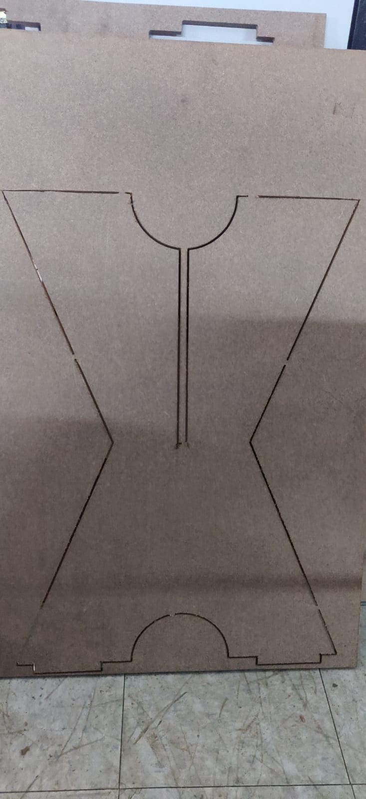
Bottom Leg piece before Cutting out tabs:
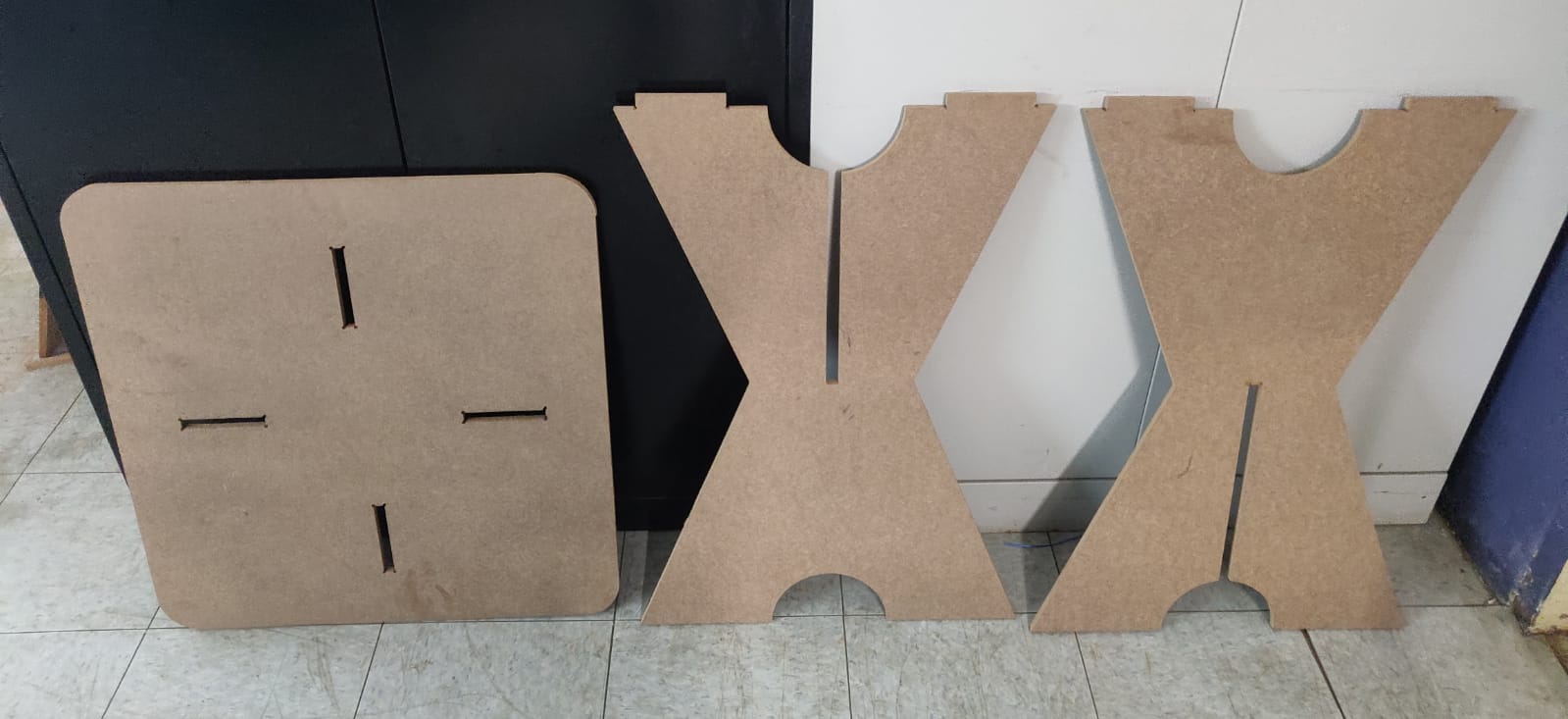
All the tabs were removed from the 3 cut pieces, then smoothed out with a utility knife. They ended up smooth enough, so sanding wasn’t necessary.
all 3 removed from sheets:
.
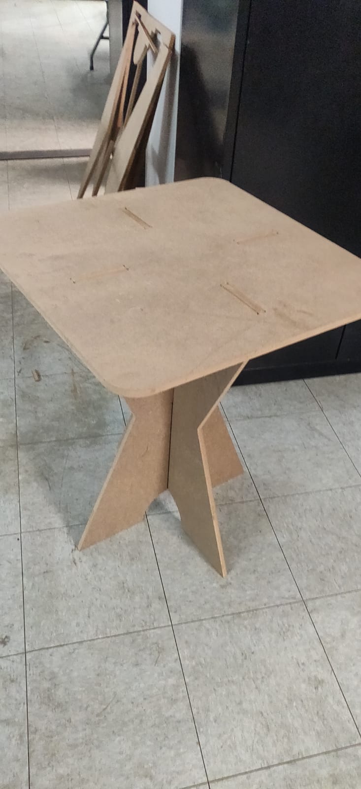
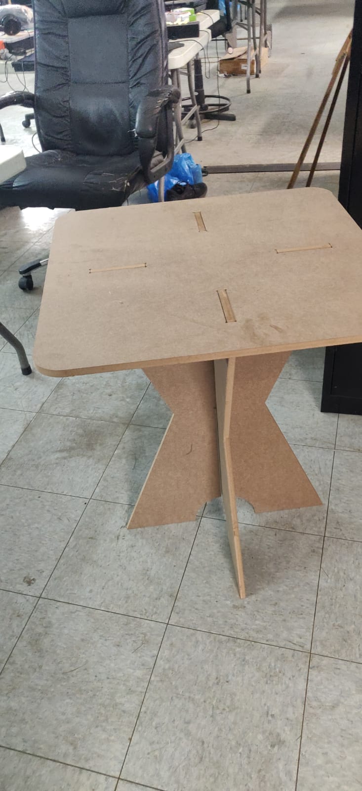
The table was then assembled by slotting together the leg pieces and placing the table top on top, lining up the grooves with the tongues.
Final table: