2. Computer Aided Design
This week was spent doing Computer Aided Design. I experimented with a few different tools for 2D design and 3D design, and picked which software packages I would be intending to mainly use throughout the Fab Academy training.
Research
There were allot of different software solutions available to us to make 2D and 3D designs. There were too many to try all in one week, so I concentrated on the ones that were recommended most by the fab academy instructors.
I wanted to concentrate my learning efforts on the solutions that I thought would be most useful for me, not only in performing FabLab activities, but in my regular job as well (running workshops, camps, and clubs at the National Science Centre). Allot of our program participants are preteens to teenager, but even our adult participants tend to have very little technical skills. Therefore, ease of use is the main factor we look for in the software tools we teach. Because of COVID-19, allot of our programs have moved to remote learning, this has introduced a new wrinkle. Participants now have to use their own hardware to run the programs, and these are often cheap laptops with low technical specs. It also means that we need to use free software so they don’t incur additional costs.
3D
From prior work, I have extensive experience with Autodesk products (AutoCAD and TinkerCAD), and a bit of SolidWorks. The two new pieces of software that I experimented with were Fusion 360 and FreeCAD.
-
TinkerCAD is a great introductory teaching tool for teaching 3D CAD. It’s free, very easy to use, completely web based and has a wide array of teaching tools built in. They also offer additional tools for connecting to some of the most popular CAM hardware. But ease of use comes at the cost of losing some technical features. We use this extensively in our teaching programs, but it is more suited to very basic designs.
-
AutoCAD has been the default go to 3D design software for decades. It is very powerful, and has almost any feature imaginable. But it has a steep learning curve and is very expensive.
-
FreeCAD was quite powerful and seemed to have all the tools and features we might possibly need. The best thing about it is that it is free. The interface had a pretty steep learning curve, and the hardware requirements were a little high. I could easily see myself using this for 3D designs where allot of technical tools are needed. But I wouldn’t recommend it for anyone who doesn’t already have some other 3D CAD experience.
-
Fusion 360 was surprisingly easy to use. Given how powerful it is, the hardware requirements are pretty low. The free version for personal use seems to have all the 3D design features that we will want to use; the only thing it lacks from the paid version is the CAM integration. This has become my new favourite 3D design tool, and we plan to use it to teach intermediate 3D design in our workshops and camps.
2D
From Prior work I have experience with CorelDraw, Photoshop and MS Paint. These work great for all our jobs at the Fablab. My motivation for picking which new software to try was mainly driven by which tools would work well for teaching 2D graphic design (mainly Vector) in our various programs.
-
CorelDraw. We use CorelDraw in-house for most of our laser cutting jobs and it works great for us. It’s a powerful vector design software package and is pretty easy to use. The only real drawback to it is the cost. We have taught vector design with CorelDraw to students with them using trial versions, but this runs into the problem of what to use after their trial period is over.
-
Inkscape comes highly recommended by allot of websites as the best free vector drawing tool available. It seems to have almost all the features of CorelDraw, although the user interface isn’t quite as intuitive. Going forward we are probably going to be using Inkscape as our main tool when teaching graphic design.
-
Photoshop has long been the industry standard for graphic design. It is very powerful and has a huge list of features (almost everything you can possibly want). The learning curve is a bit steep, but the main drawback is the price.
-
MS Paint is ubiquitous image editing and creation program included in Microsoft Windows. Every windows user already has it installed and it has all the basic and intermediate features that most people need. I tend to do most of my image editing with it because it is just so familiar and always available.
Assignment
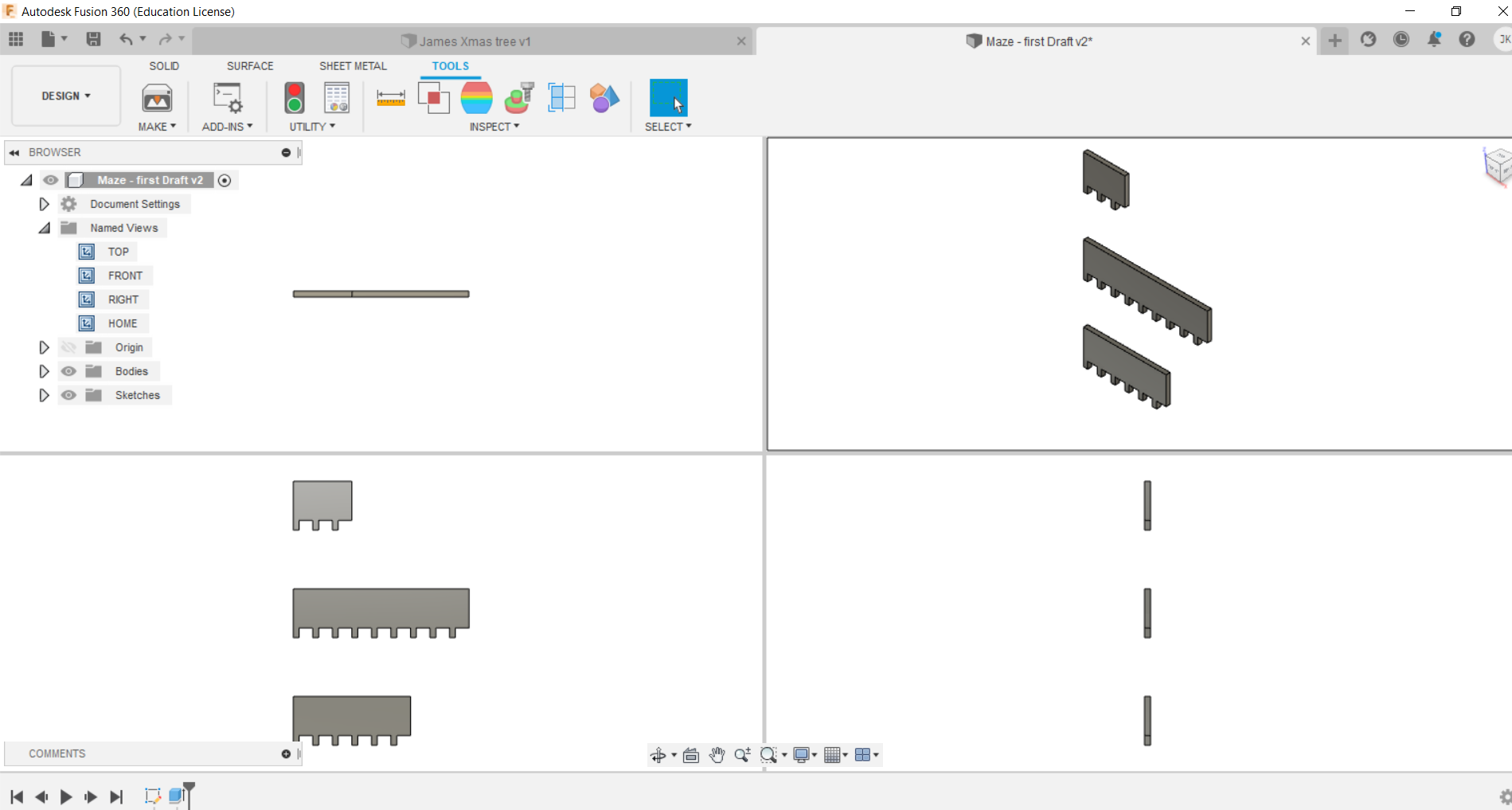
This week’s assignment was to create a CAD design of part of our final project. I made the design using Fusion 360.
My final project is a modular maze for use in introductory robotics competitions. The project consists of multiple base floor pieces with a pattern of repeating holes throughout. These base pieces are placed side by side on the floor, and wall pieces are places in various patterns on the base to create the maze.
The wall pieces will all have the same height, but different lengths, so that a wide range of layouts are possible. The wall pieces will have protruding pegs built in so that they can slot into the holes on the base. Because I haven’t yet finalized the dimensions and materials to be used in the final project, I used variable parameters and allot of equivalences in my design. This means that what once my material is chosen, and my dimensions are finalized, I only have to edit the parameter settings in the drawing to get the correct results.
The constraints I implemented for my design are as follows:
- Wall thickness – this is the thickness of the material chosen. The pegs at the bottom are square and are as thick as the wall material. Therefore the peg width has to be the same as the wall thickness.
- Wall height – This is the height of the wall that protrudes above the base. The wall height hasn’t yet been determined, so it was left as a parameter. (I chose a tentative height of 20mm just so the other features of the drawing are noticeable, but the final dimension will be closer to 200mm)
- Wall Length – This is the length of the smallest wall segment. The other wall segments will be multiples of this length. (Although the same overall length can be achieved by only using many of the smallest wall segments, the final maze will be sturdier with longer segments where possible)
- Base depth – This is the thickness of the material used as the base. The thickness of the base dictates how deep the pegs can go, and hence the length of each peg.
- Node separation – This is how far apart the holes on the base will be from one another. This dictates how far apart the consecutive pegs on the wall pieces must be from one another.
Creation:
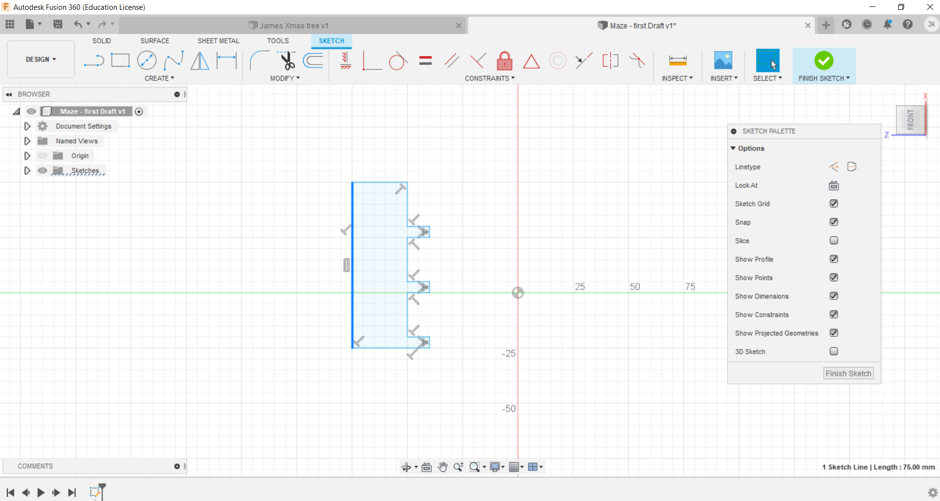
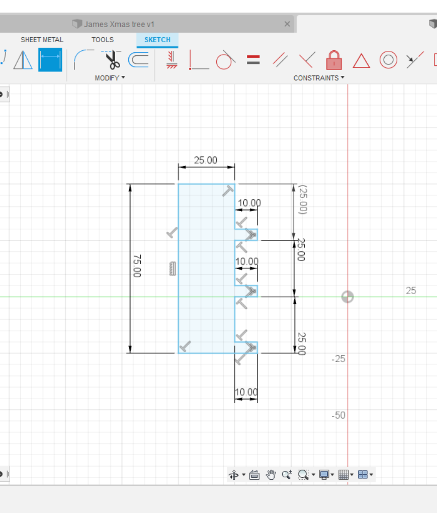
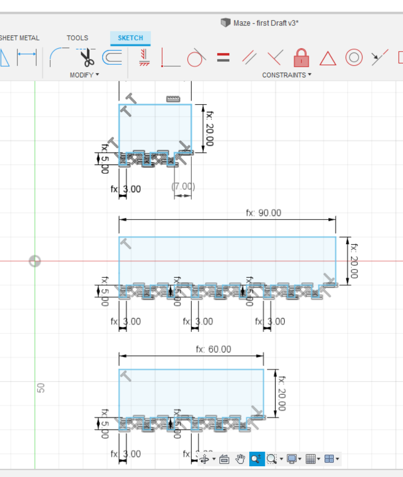
A rough flat sketch of the smallest wall was first created, without using proper dimensions. I then created a bunch of equivalencies so that all the lengths that were supposed to match one another were marked as such. Because there are allot of equivalences on the drawing, it looks a bit cluttered in the drawing at the scale shown.
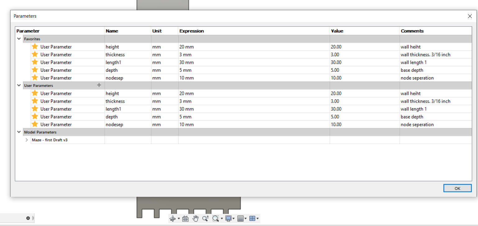
Then I created the parameter table and populated it with values. (Interim values till a final determination is made)
Then I set the dimensions of the walls to the appropriate parameters. (This also included a math function for the length between nodes [node separation minus wall thickness]). Because of the equivalences, only 5 dimensions needed to be allocated, and everything else adjusted to the proper size.
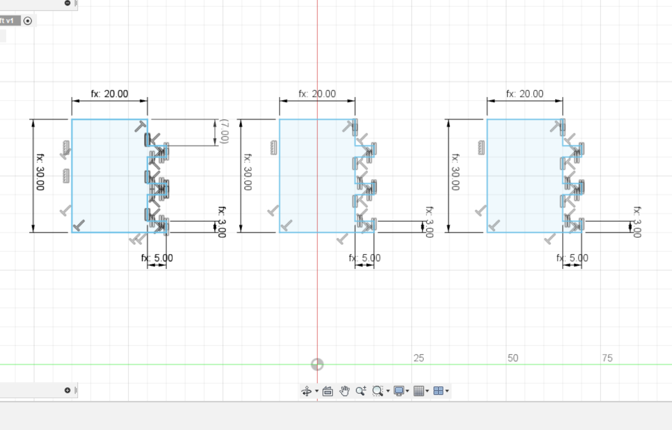
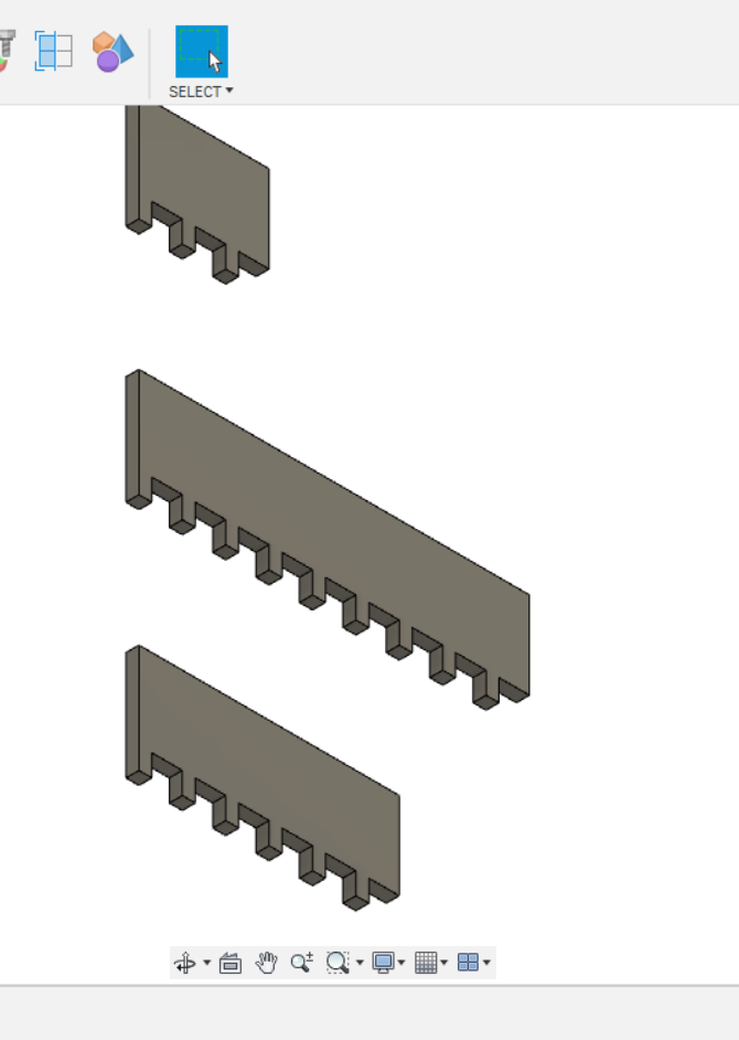
To make the middle and long wall segments, I simply copy and pasted the existing segment onto itself so that the pattern repeated, and then deleted the line where they would have joined.
The final task was to extrude the flat drawing to the thickness of the wall pieces (also parameter).
My 3D design files are available here:
Maze-Draft-V5 F3D file (native Fusion format)