1. Principles and practices and Project Management
This week was spent familiarizing myself with the tools and methodology for documenting my progress throughout the Fab Academy training (GIT, version control, Web development, Linux and documentation tools). I also came up with a Final Project idea and conceptualized aspects of features (This project idea may change or be replaced as I work through the course, but it’s a good starting point).
Research
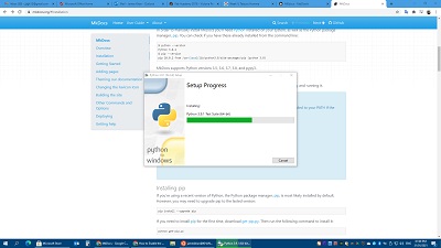
The first few days were spent going through tutorials on GIT and trying to familiarize myself with the terminology and how the system works.
When starting to launch some of the tools there were a few “hiccups”. I am a native Windows OS user, so there was a steep learning curve in using Linux, (since most of the tools were demonstrated and documented from Linux). Windows offers a Linux shell, but I encountered numerous errors in installing some of the required libraries for the necessary applications. Troubleshooting proved difficult because I couldn’t determine if the issues were with the libraries, my command syntax, or with windows itself.
After a couple days of trial and error and testing, I decided to stick to mostly GUI programs and slowly migrate to the BASH Linux implementation within Windows as I became more familiar with the tools. That way I could always fall back on a familiar interface when encountering problems while maintaining my documentation site. Learning to use the syntax within Markdown was quite easy given the templates we were given.
Programs used
The programs I settled on using were:
- Brackets with Markdown extension for creating and editing web pages.
- Sourcetree for pushing and pulling files to the GIT page.
- MS Paint for photo editing and resizing.
- HandBrake Video Editing and conversion.
Quick “cheats” and hints.
I had to constantly switch computers while doing my Fab Academy work. I had to switch between my work computer, home computer, and computers that were dedicated to certain Fab Lab equipment. There were administrative restrictions to installing software on the lab and work computers. This made it a hassle to involve our IT department to install or update software when needed. For convenience and efficiency this meant that, as much as I could, I tried to rely on built in Windows tools or web based software.
-
Video/Picture compression. WhatsApp. We were instructed to keep the file sizes of our media files small, so that each assignment took up no more than 10Mb total (or at least try not to go too much over). Pictures and videos taken on your phone can sometimes be huge, so we usually need to compress them before uploading. I did a sneaky “cheat” to quickly compress my videos and pictures. I simply WhatsApped the picture and video files I took on my phone to myself. I then logged into WhatsApp Web and downloaded the media files back onto my computer. This solves both the problem of transferring the files from my phone (which I used to take the pictures/video) to my computer, and of compressing the files, because WhatsApp has built in compression for media files. The amount of compression I got from WhatsApp seems perfect for Fab Academy’s suggested repository size. For example, this random photo I took on my phone is 4.25Mb originally (with my phone’s default photo settings), but WhatsApp compressed it down to 137Kb.

-
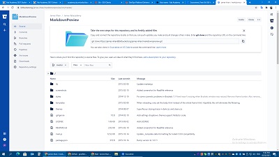
Updating my Git repository (THIS SITE). WEB IDE. I found that the most convenient way to update my website on the Git repository was to use the built in Web based IDE (integrated development environment). This is a web based tool that replaced using Brackets and Sourcetree for me. It was also more intuitive. Simply go to https://gitlab.fabcloud.org/academany and search for your name in the left search bar. Then click “EDIT” and “WEB IDE”. IF you have logged in properly you should be able to edit your own repository.

-
Screenshot Capture. In Windows OS, easily capture the contents of your screen by pressing the “windows key” plus “PRT SCRN button” (this may be labeled differently depending on your keyboard, but stands for “Print Screen”, for lots of keyboards this may be something like “FN key” plus “Home key”). The screen should briefly flash. Then the file of the screen capture should be stored in your “Pictures/Screenshots/” folder. This’ll come in really handy.
-
Screen Video capture. Windows 10 and 11 have built in tools for creating a video of everything on your screen for a specified time period. This can be great for demonstrating something you did. Here’s a good article on how to set it up: Using Xbox Game Bar for Video recording.
I will likely change tools as I start to need more sophisticated features and gain confidence and familiarity with Bash Linux.

Updating my Git repository
As I indicated above, switching to the WEB IDE made updating my GIT repository way more convenient.
-
This was mainly because I was working from multiple computers.
-
To upload files from your computer simply drag and drop them into the relevant folder in the web interface. You can also create new files and folders similarly to how you would in a normal windows explorer interface.
-
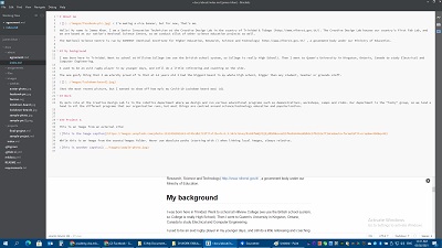
The Web IDE has a preview side a panel that lets you see how your markdown page that lets you view a sample of your page before you commit. I have found that this works even better than Brackets. (2 in the picture below)
-
To update (PUSH) your repository after you’ve made changes in the IDE, simply click on “Source control” (#1 below) and then click “Commit and push to master”. You can also see details about all the changes that will be made in this push, like which files you created or modified.

- BACKUP. If you go to a page on the Academany Fabcloud, you can click on “code” and “download source code” as a “zip” file. This will compress all the files in that repository and download a local copy to you. You can do this as a periodic backup or “PULL” for the code on your local computer. This can also be done for subfolders or individual files. You can also do this for other people’s repositories, not just your own.

- the XXXX.md files are your markdown files and refer to the main body of your webpages. This is where you edit your text and insert images or links. If you aren’t sure how to get a certain feature in a markdown, one easy way is to see what others have done.
- If you see some formatting you want on another fab academy students markdown webpage, you can search for that student’s name in https://gitlab.fabcloud.org/academany just as you did to get to your own page. then you can click on them, and the address of any of their “pushes”. You should be carried to a webpage like https://gitlab.fabcloud.org/academany/fabacademy/2021/labs/vancouver/students/james-khan, this is mine for example.
- From here you can select the MD file of webpage you want. It might be under a subfolder like DOCS/ASSIGNMENTS/
- Once on the correct file, you can press DISPLAY SOURCE “” to see how they were able to implement certain formatting in markdown. Things like displaying video, tables, bullet points, YouTube links, etc.
Housekeeping
This isn’t necessary, but it’s what I did to help keep things in order.
-
In both the “FILES” and “IMAGES” folders, I created a subfolder for each weeks assignments and named them week01, week02, … week20. I put all the image and video files in that week’s subfolder in IMAGES. I put all other file types in that week’s subfolder in FILES. This just helped me keep more organized, since allot of files were expected.
-
When I thought I was done with a markdown page, I would copy all the text into clipboard and paste in into a work processor like Microsoft WORD. This would just highlight all my spelling and grammar mistakes so that I can go back to the markdown page and correct them. (It would have been nice if the Web IDE worked with the spell checker built into the web browser).
Final Project (tentative)
Simplified
A modular and maze with electronic features to be used in robotics training tutorials and competitions.
Problem description
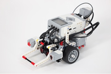
I work in the Robomania section at our National Science Centre. We run robotics demonstrations, workshops, camps and clubs. One of the best kits for teaching robotics is the Lego Mindstorms EV3 kit. One of our most useful challenges is getting students to build and program a robot to solve a maze and pass through it. The current maze we use has some major problems:
- The maze itself is bulky and heavy, making it difficult to transport when we run the activity at remote locations.
- The maze design is fixed. We give students free range to use whatever programming techniques they want to “solve” the maze. Rather than come up with an intelligent program that can solve a variety of maze configurations, some students use a brute force technique (e.g. programming the robot to go 10cm forward, then turn left 90°, then 30cm forward, turn 90° right......). This requires a lot less thought about the robots algorithm.
- Difficulty is fixed because the maze is fixed. When we encounter particularly talented students who come up with a working solution quickly, we can’t adjust the mazes difficulty to give them a harder challenge.
- The maze is a little plain. Its part of a robotics challenge, so having just a wooden maze with no shiny techy features isn’t as visually enticing as it could be.
Solution
A Modular maze that can be: - Easily broken down and set back up for easier transport. - Reconfigured into various layouts to add more challenges. - Has electronic features to make it more exciting. (Electronic timer and barrier)
Schematic
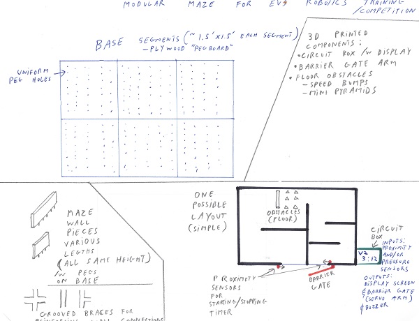
- Maze base will be designed like a peg board with uniform holes throughout. They will be made of individual pieces (likely plywood) about 1.5’ x 1.5’ that can be joined together to make the larger whole base.
- Maze walls pieces will be made of plywood or MDF with appropriately spaced pegs on their base to fit into the holes on the base. The wall pieces will be made to the same height, but varying lengths so that they a variety of layouts can be achieved.
- Grooved brackets will be cut to reinforce the walls to add more stability to the chosen layout. Wall pieces may need to have grooves cut into their ends to accommodate brackets.
- Grooved paths along wall pieces for clean running of electrical wires for sensors/servos. (Potential future upgrade)
- Electronic control. Connected to proximity sensors (or pressure plates) that control the timer and barrier gate. Servo for barrier gate. Display for timer.
- 3D printed mounting brackets for sensors and servo (s). 3D printed electronic box for display and circuitry.