5. 3D Scanning and Printing
3D printing
About FDM printing
3D printing involves creating solid real world 3 dimensional objects from a digital file by using an additive process. The additive process takes some type of raw material and forms it into the desired object, so there is always some type of consumable used. There are a few different methods for implementing this additive process, including Stereolithography (SLA), Selective Laser Sintering (SLS), and Digital Light Process (DLP); but the most popular by far is FDM (Fused Deposition Modeling). FDM Printers are what most people think of when they think of 3D printing, almost all of the home 3D printers that hobbyists use are FDM. This is because FDM printers tend to be the most affordable both in machine and consumable cost. They also tend to be the easiest to learn to use. FDM printers take a consumable, usually a type of plastic filament (long roll of “string” of a fixed thickness). They feed it into a heated nozzle that melts the particular type of filament to a specific temperature. The nozzle moves around in a pattern squeezing out this melted filament onto a surface below. The melted filament attaches to any filament it was placed onto and rapidly cools back down to a solid; this “Fuses” the “Deposited” filament layer by layer to make our desired object. At our lab we have a few FDM Printers, including:
• Prusa Mini, and
• Prusa MK3S+. The Prusa MK3S+ is our newest and best printer.
Group Assignment
Working as a group, me and the other fab academy students here (Cristopher Proute, Terrence Carew, Nervene Bhagwandass, Marvin Holloway, Ravi Baldeo) investigated and tested the design rules of the printers we have in our lab and documented the features and limitations of those printers. We did allot of the tests on the FlashForge Creator Pro. This was because it was an older printer and the flaws and challenges of 3D printing are more apparent. We did some of the final testing on the Prusa MK3S+, our newest and best printer. You can see our results here.
My FDM Print
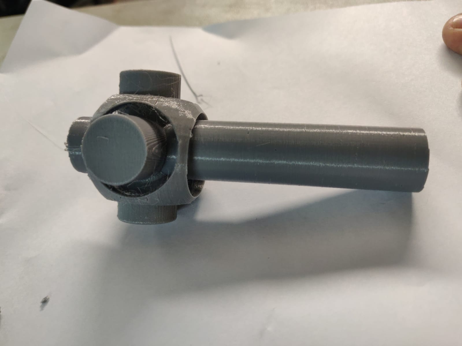
For my 3D print I made a sort of “rattle”. It’s a pretty basic design: a shaft which branches out in 5 directions near the end, with the shell of a sphere with holes in it surrounding the 5 branches. Although this design is simple, it would be very difficult to make this 3D item with a subtractive manufacturing technique. The geometry of the rattle means that it is virtually impossible for a milling head to get to the inside surface of the sphere without some incredibly tiny joints of articulation.1
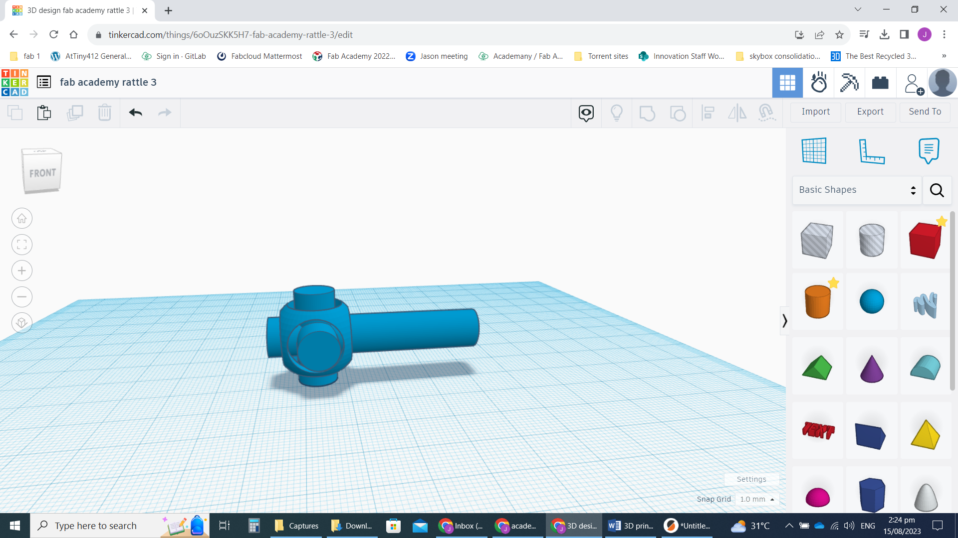 my final design
-
The CAD file: rattle STL File
-
Me designing rattle in TinkerCAD (youtube) Recorded using windows 10 built in screen recorder (windows key+alt+R).
same video local copy (lower quality):
Because the drawing was fairly simple, I did it in TinkerCAD www.TinkerCAD.com . We tend to use TinkerCAD to introduce high school students to CAD in allot of programs we run at our Science Centre (where I work with the rest of my local Fab Lab). I like to work in TinkerCAD even for more complex drawings in order to get and stay proficient with the more advanced tools it has and work out my own “tips and tricks”, so I can answer every possible question posed by students. I have found that TinkerCAD can do almost everything I want to do in CAD except for parametrics.
3D Slicing
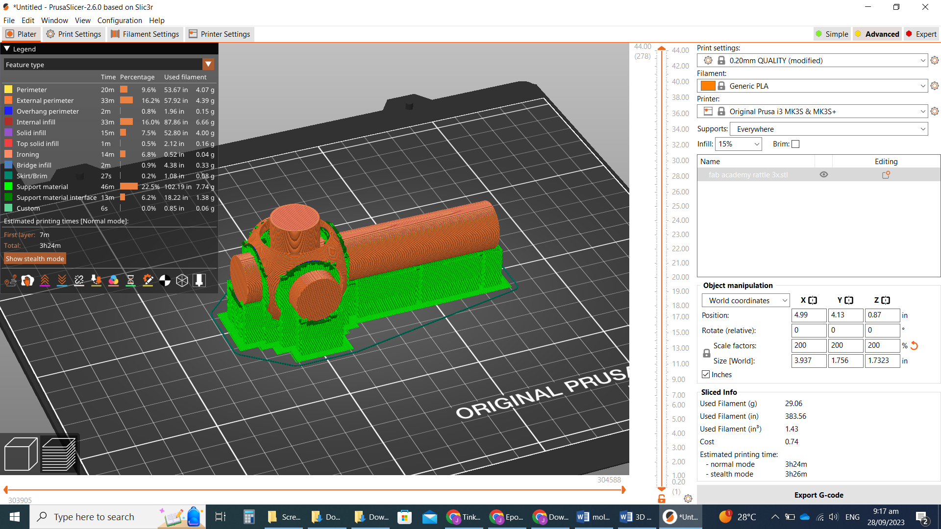
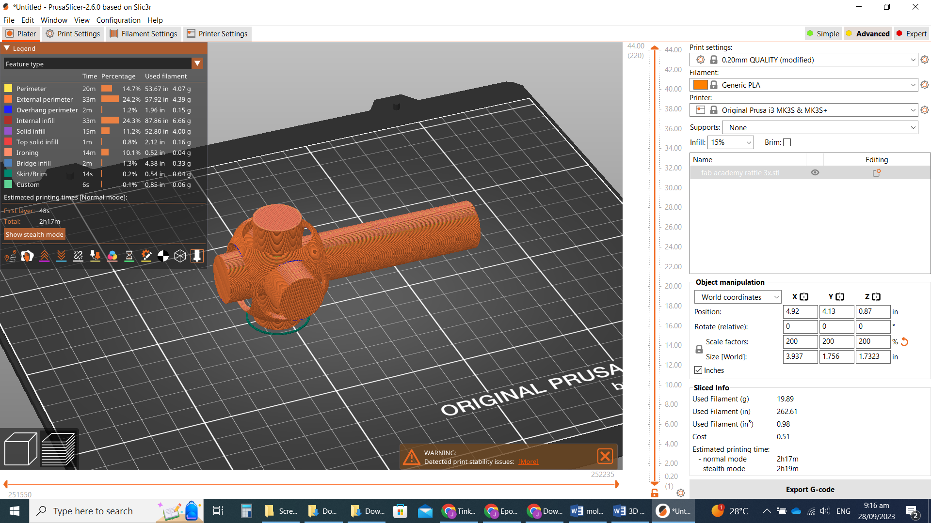
From TinkerCAD I exported the drawing as an STL file. And opened that file in Prusa Slicer. Prusa Slicer is known to be one of the best 3D slicers out there. I will also be printing with our Prusa MK3S+ since it is our best and newest printer. I made the original drawing a little small, so I scaled it up 200% in the slicer. My drawing has some of its parts “hovering” above the print bed, no matter what its orientation, supports will likely be needed. I generated gcode for the print oriented horizontally and vertically as well as with and without supports. This let me compare all the simulated results. The rest of the slicer settings were the same:
• System preset: 0.20mm Quality (default settings)
• Generic PLA heat settings
• 15% infill
• Prusa MK3S+ printer
Simulation results:
• Horizontal, with supports (everywhere setting): Filament: 29.06g, Time: 3h 24m
• Horizontal, no supports: Filament: 19.89g, Time: 2h 17m
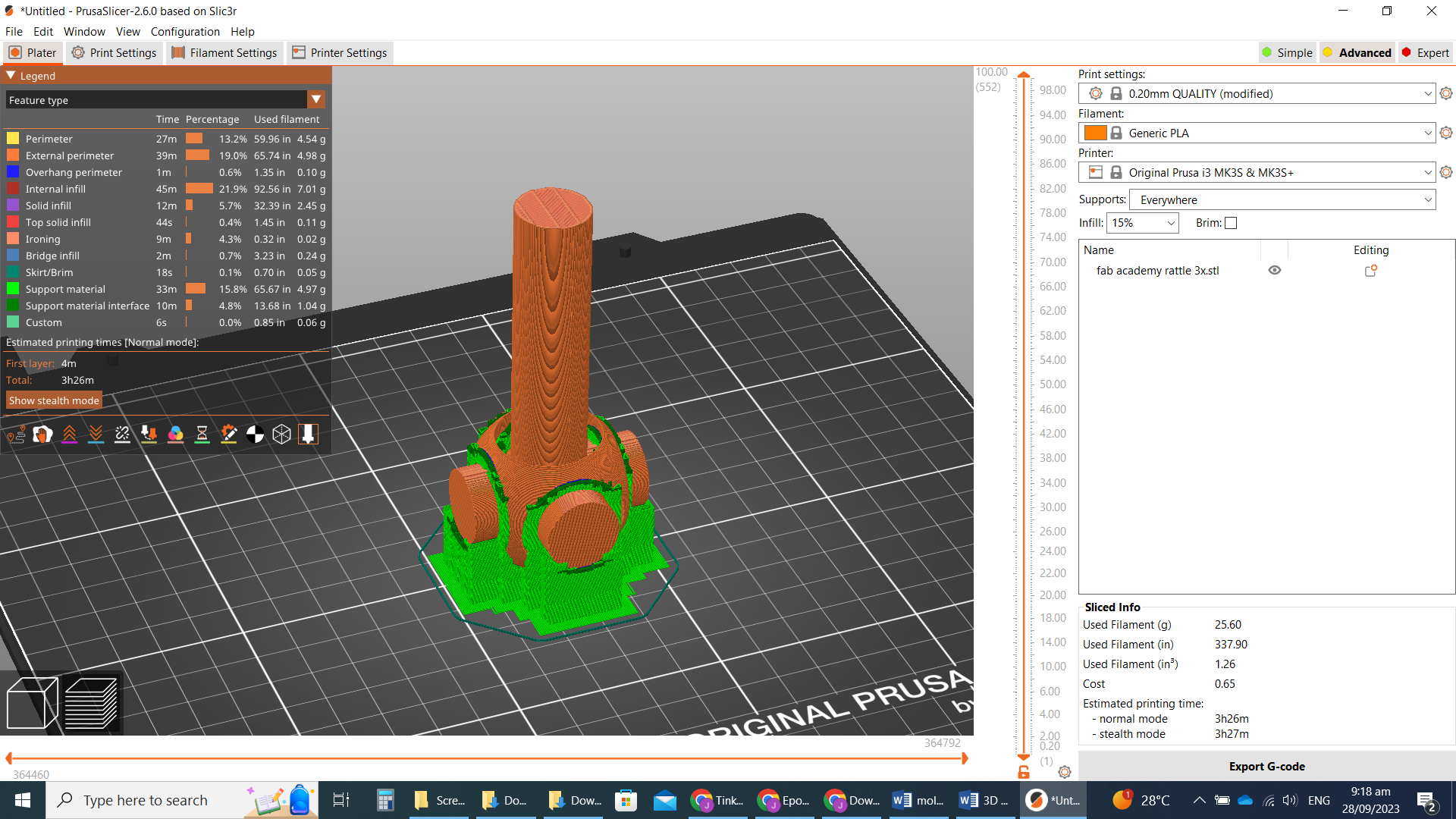
• Vertical, with supports (everywhere setting): Filament: 25.6g, Time: 3h 26m
• Vertical, no supports: Filament: 19.57g, Time: 2h 37m
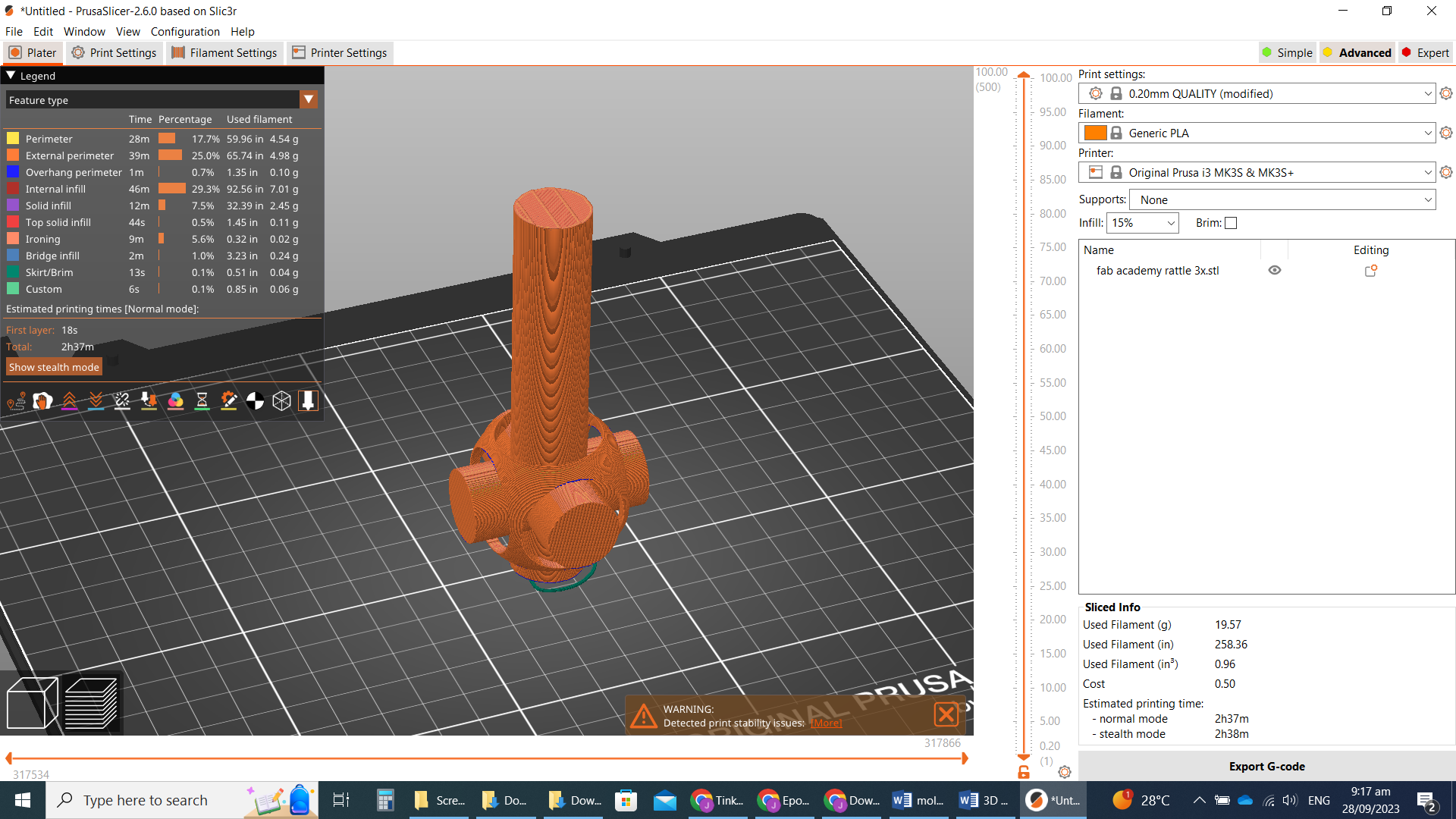
It is noteworthy that despite using the same amount of material as the horizontal, the vertical “no support” print takes longer. This I surmise is because the vertical movement of the printer head is far slower than the horizontal movement. The geometry of the drawing means that allot more filament is needed as support for the horizontal print than the normal vertical, as indicated by more filament being used. Although the horizontal uses allot more filament, it still takes roughly the same amount of time, because of the same traversal path issue as the non-supported.
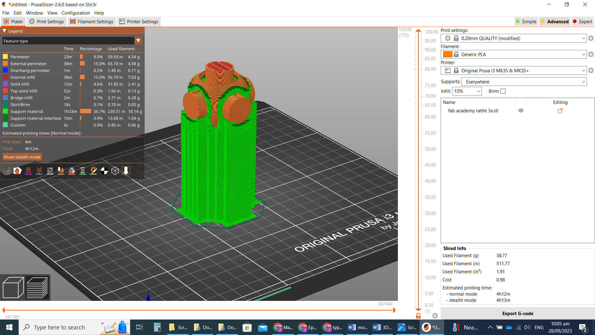
Just as an experiment/demonstration I simulated the vertical print with the head of the rattle pointing up, higher above the print bed:
• Vertical, with supports (everywhere setting), head pointed up: Filament: 38.77g, Time 4h 12m
• Vertical, no supports, head pointed up: Filament: 19.57g, Time 2h 27m
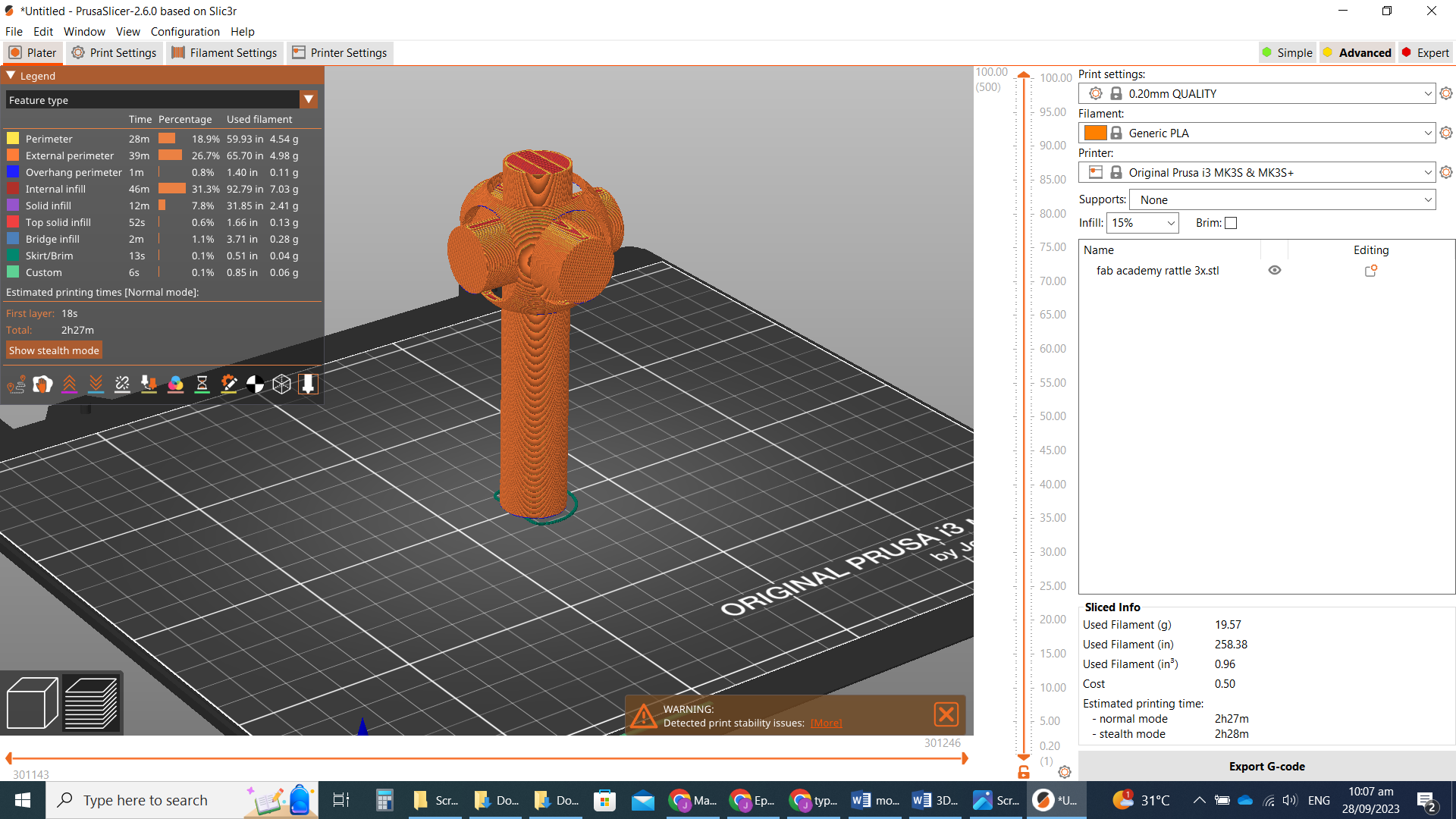
We can see that allot more material is used to print the supports when we make this inversion. This print will require supports in order not to fail, so if we want a good result, the choice is between “horizontal with supports” and “vertical with support (head down)”. The vertical uses less material, but having a tall, slim print means that if a small flaw occurs, there is a greater chance of a catastrophic failure to the whole print. The long shaft of the object is kind of a handle, so being smooth to the touch would be preferred. The points of contact with the support and object leaves small burs when the supports are removed; these could be sanded down, but the best result is not to have these burs on the handle at all. So I decided that the best print would be the “vertical with support (head down)”.
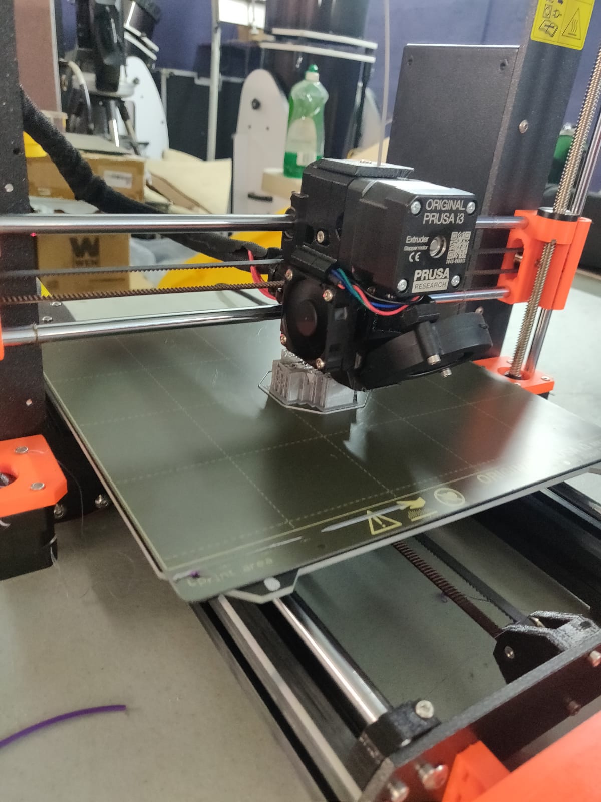
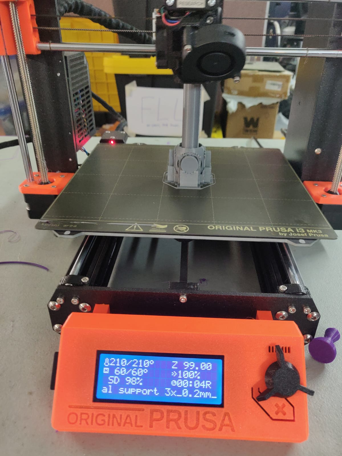
Printing
I printed with PLA filament (Matterhackers brand). All I had to do with this printer was copy the gcode generated by the slicer to the SD card, load the card into the printer and select print from the menu. Bed heating and leveling are done automatically.
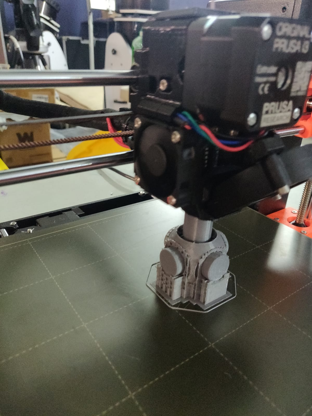
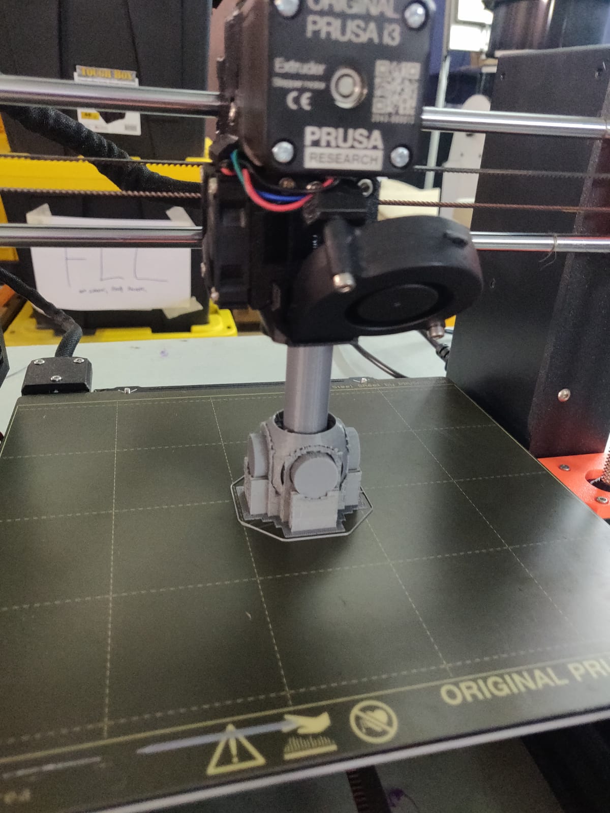
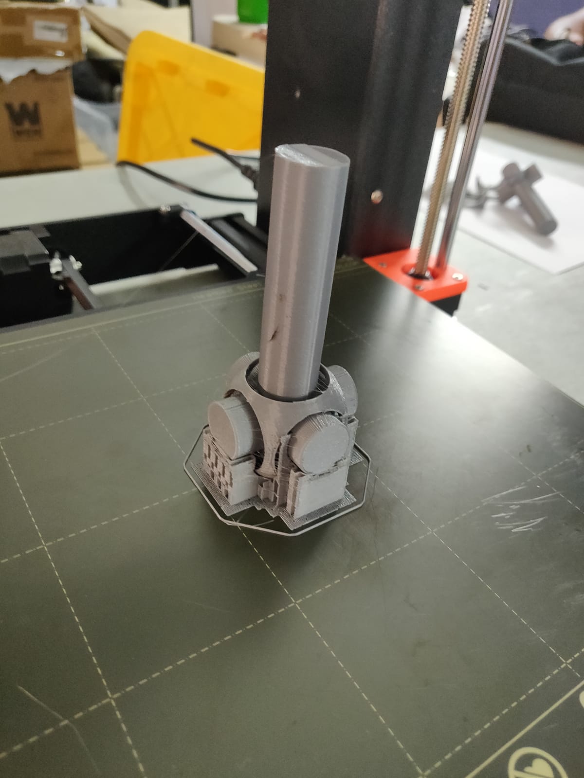
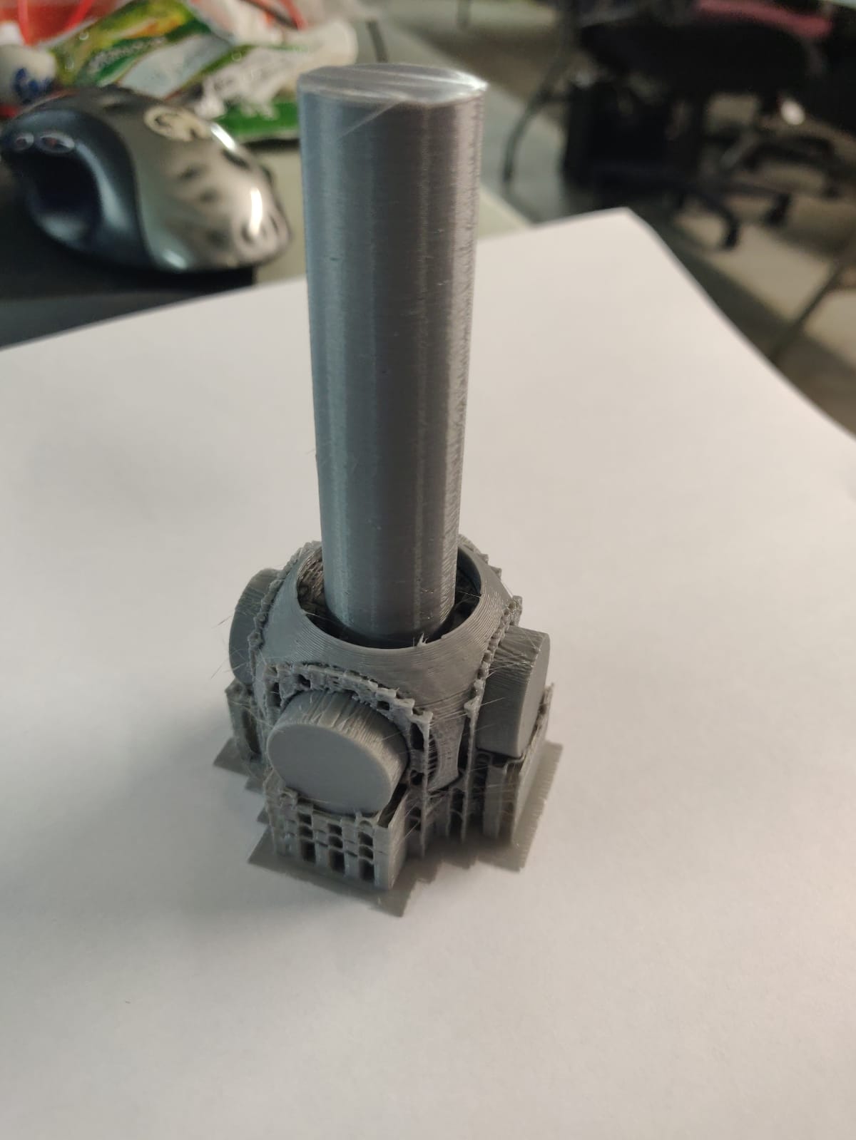
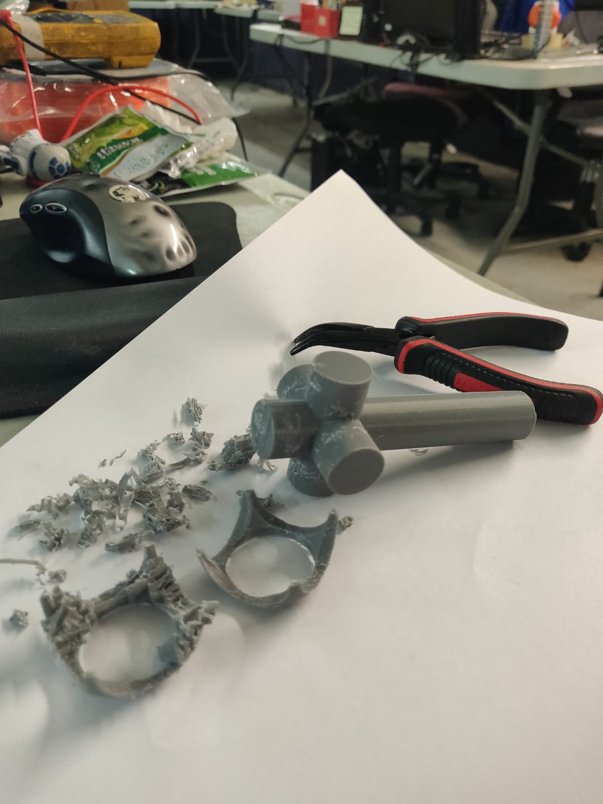
FAILURE: The printed object with supports looked pretty good. HOWEVER the density of support material was too high, and the sphere too delicate. The supports were pretty strong; while removing them with a small bird’s beak pliers, the sphere developed a couple of cracks and broke off.
So I changed the settings in the slicer from “Supports: everywhere” to “supports: support on build plate only”. But I also realized that since the sphere was hovering, I could actually move it lower to the bed in the original CAD drawing, and hence need less support. So I made the changes in the CAD drawing and redownloaded it:
• New Vertical with lowered sphere and build plate supports only. Filament: 23.82g, Time: 3h 1m
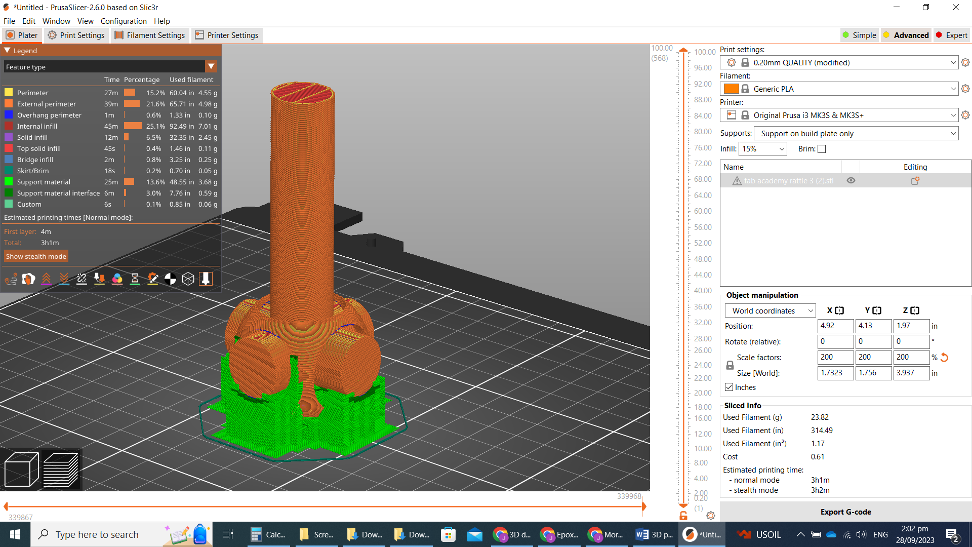
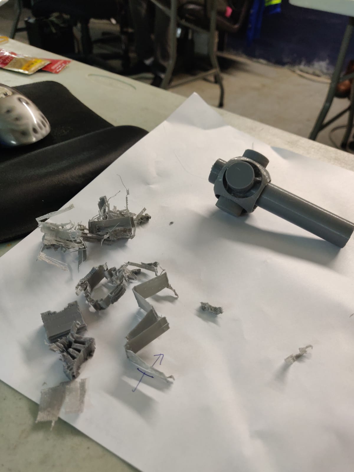
- Final Print (updated and removed supports)
3D Scanning
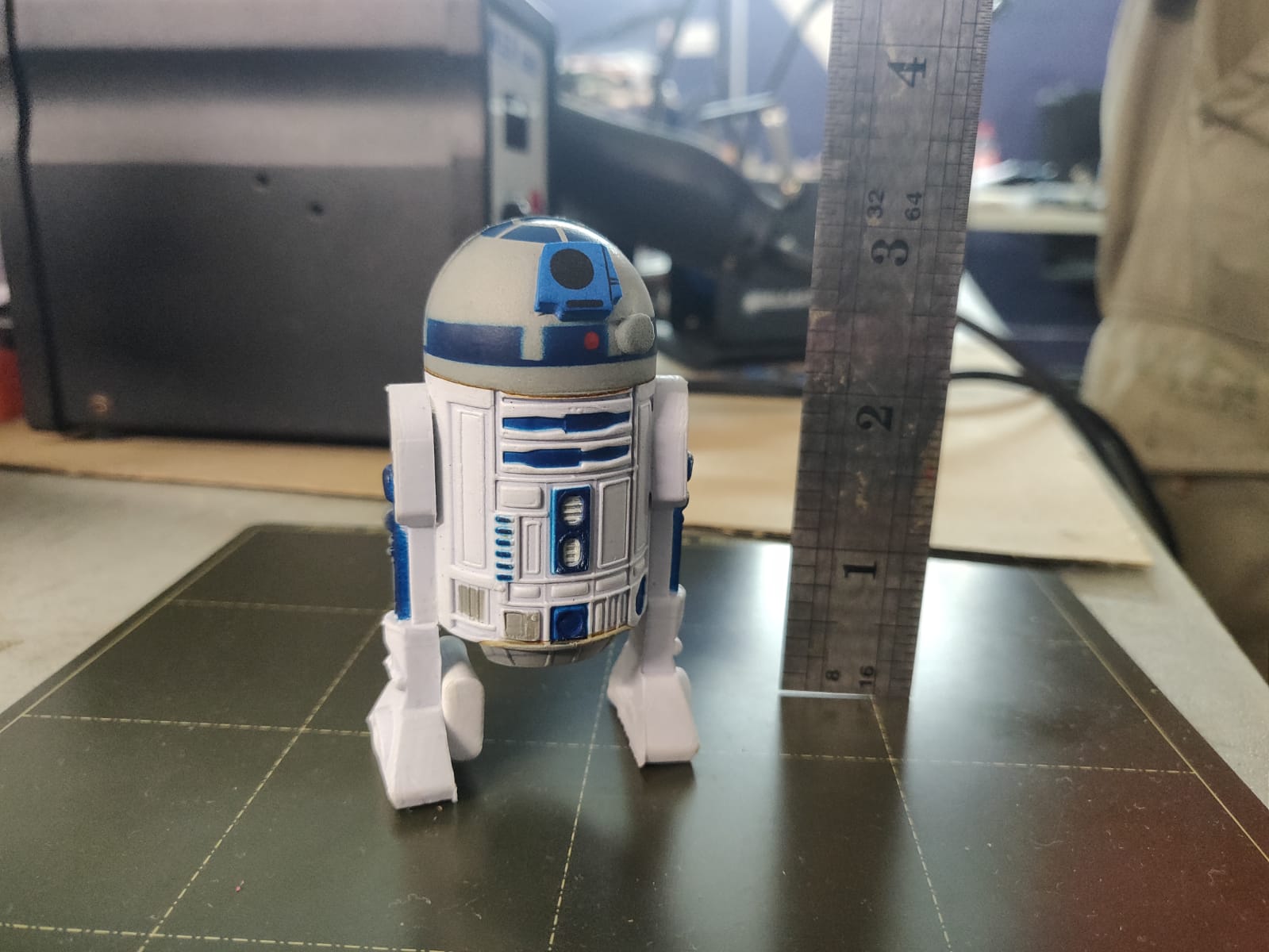
The objective is to scan a 3D object. It makes the most sense to scan something that has enough details that it would be tedious to try to reproduce it from scratch in CAD. I chose a small rubber model of R2D2 from Star Wars (just over 3 inches tall).
For 3D scanning most resources suggest using smart phone apps to get the scan. People in our lab looked at a few different apps: - SCANN3D, Used by Terrence Carew - KIRI Engine - QLONE, Used by Marvin Holloway - WIDAR. This is the one I eventually chose. It seemed to be well reviewed, and was also recommended by a friend with some experience.
Using WIDAR
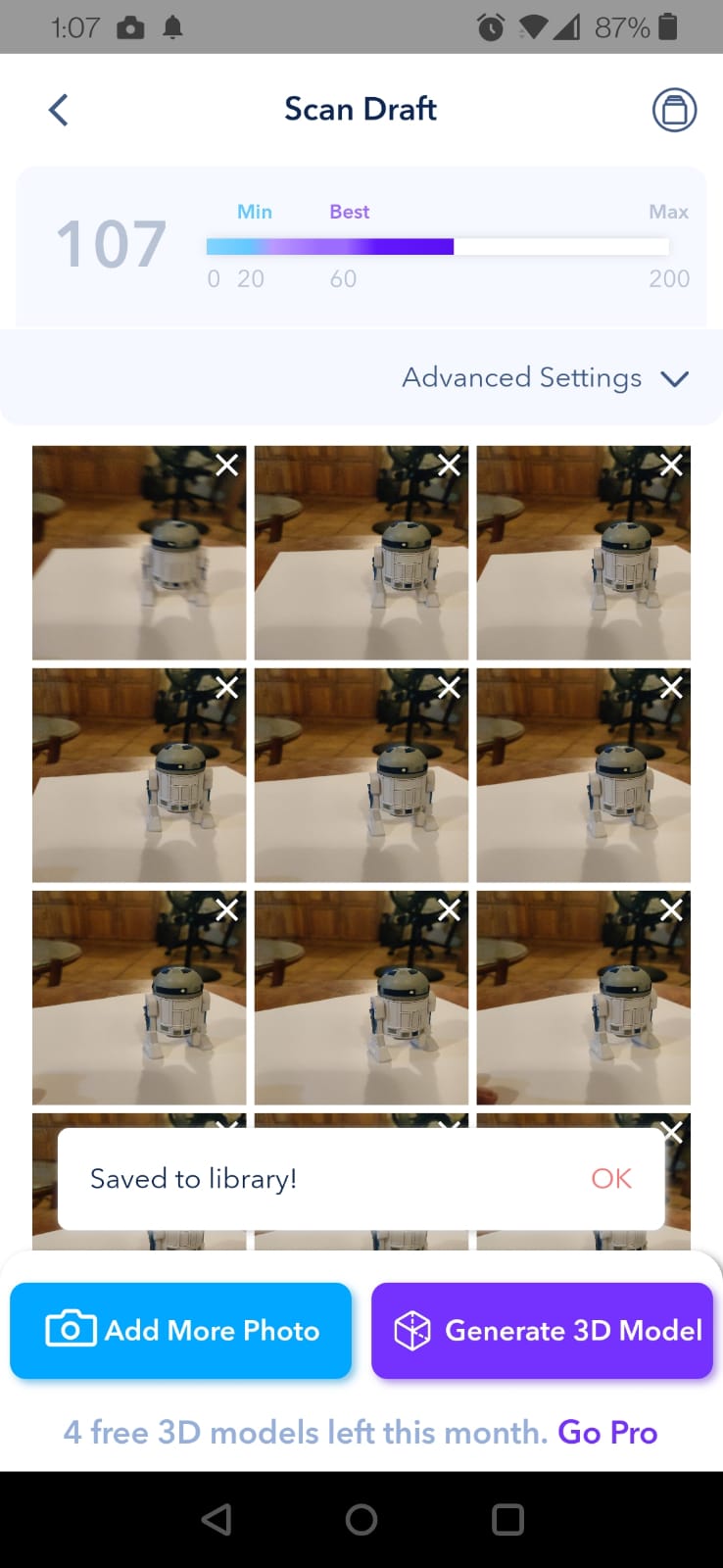
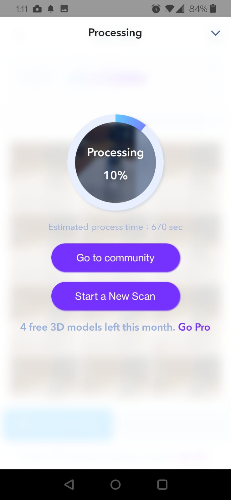
The process was quite simple: place the object on a flat surface hit “record” in the app and move the phone’s camera around the object and try to get as many angles as possible. The app takes a photo every 1 second or so with a small click sound to notify that a pic was taken. A minimum of 60 pictures are needed, but you can take up to 200 pictures for a better 3D scan result. - I initially tried using 70 pictures, but my hand wasn’t very steady, so the results were poor (R2D2 was missing a “leg”). I deleted the result so quickly, I forgot that I should have kept the “failure:
- My second atempt went much better, I took 107 pictures.
-
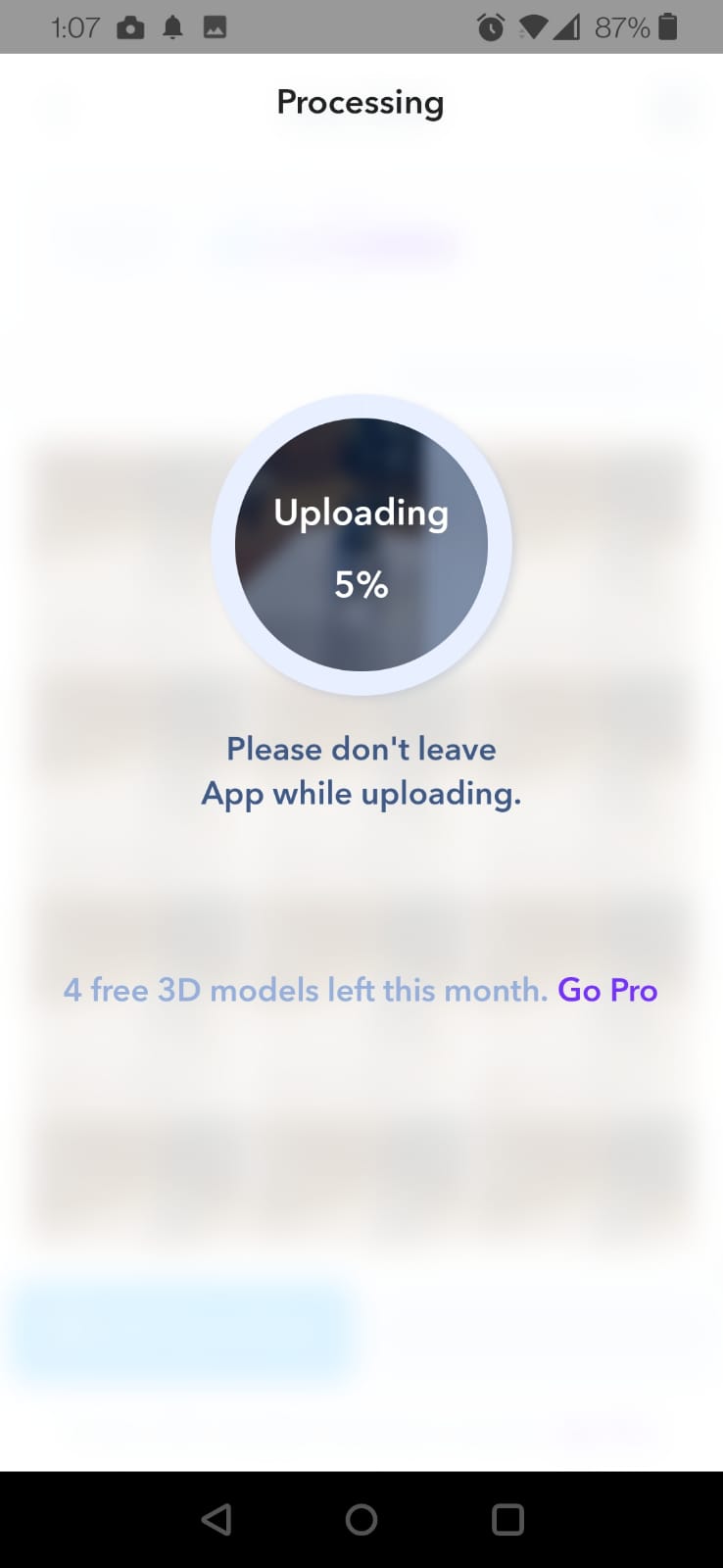
The pictures are automatically uploaded by the app, and then processed online before sendoing the result back to your phone.
-
THese were the final images of the scan. I was able to rotate and manipulate the scan on the phone with ease:
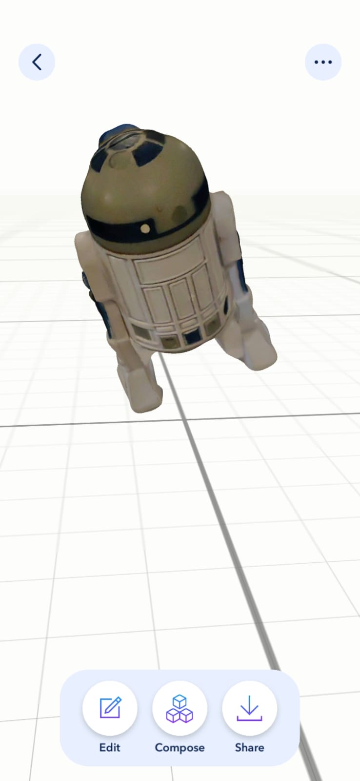
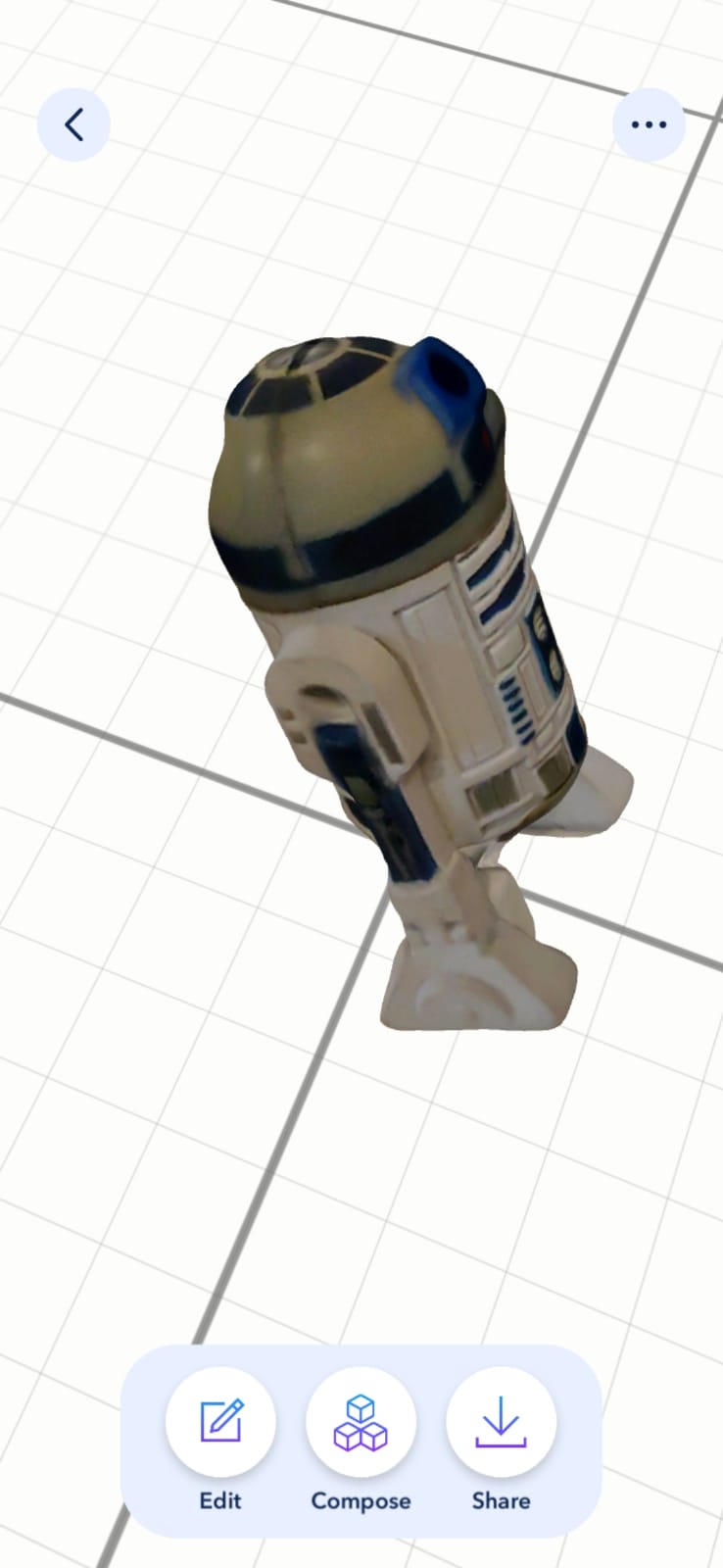
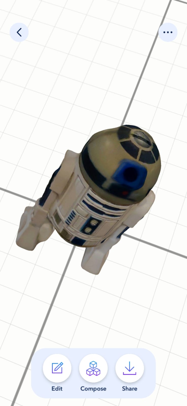
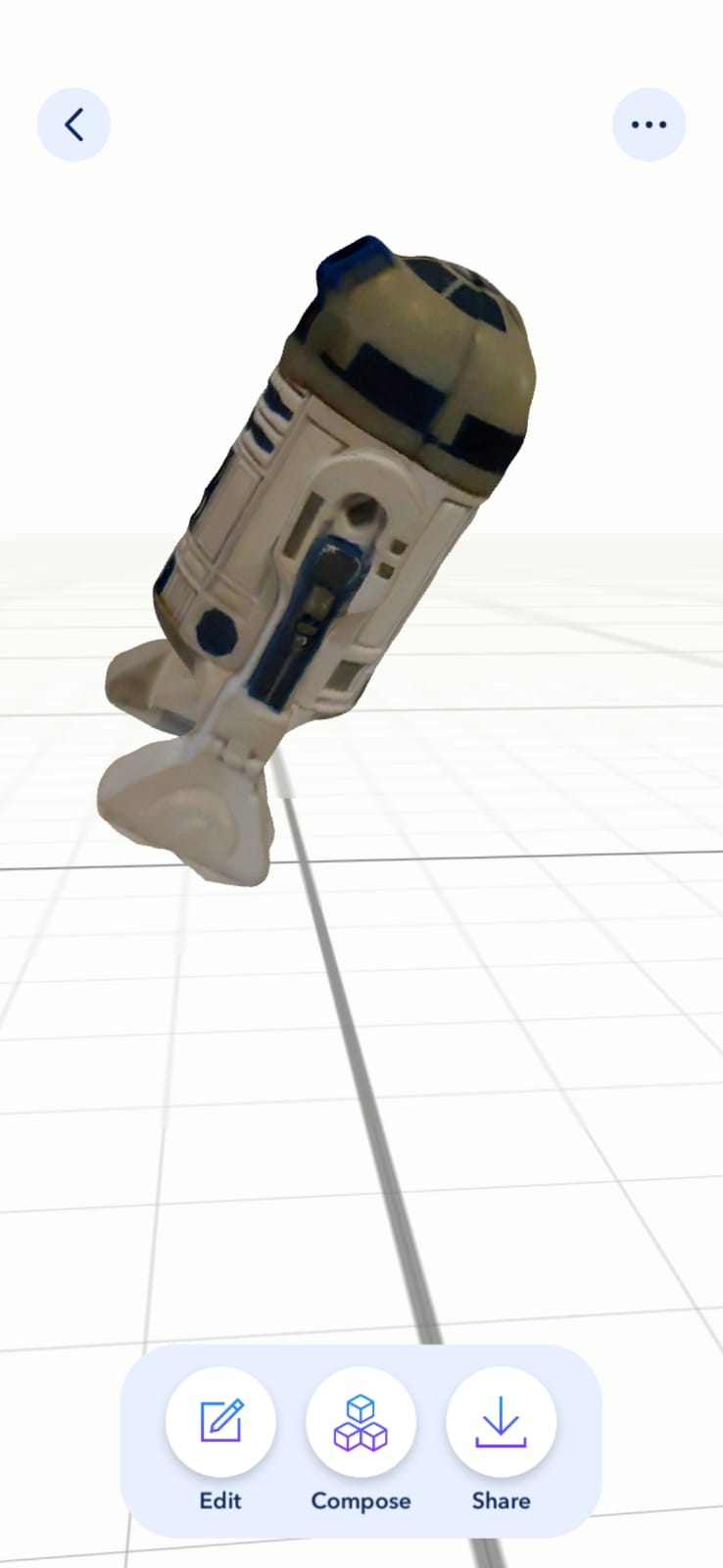
-
The only “odd” thing about the scan result is that the final object was a little tilted relative to the 3D environments horizontal plane, but that is easily fixed in any program we use the scan in.